Nahezu alle Menschen werden zunehmend mit den Anwendungen der „Künstlichen Intelligenz“ (KI oder AI für engl. Artificial Intelligence) konfrontiert. Musik- oder Videoempfehlungen, Navigationssysteme, Einkaufsvorschläge etc. basieren auf Verfahren, die diesem Bereich zugeordnet werden können.
Der Begriff „Künstliche Intelligenz“ wurde 1956 auf einer internationalen Konferenz, dem Dartmouth Summer Research Project geprägt. Eine grundlegende Idee war dabei, die Funktionsweise des menschlichen Gehirns zu modellieren und darauf basierend fortschrittliche Computersysteme zu konstruieren. Bald sollte klar sein, wie der menschliche Verstand funktioniert. Die Übertragung auf eine Maschine wurde nur noch als ein kleiner Schritt angesehen. Diese Vorstellung erwies sich als etwas zu optimistisch. Dennoch sind die Fortschritte der modernen KI, beziehungsweise ihrem Teilgebiet dem sogenannten „Machine Learning“, nicht mehr zu übersehen.
Um die Methoden des Machine Learnings näher kennenzulernen, sollen in diesem Buch mehrere verschiedene Systeme zum Einsatz kommen. Neben dem PC werden sowohl der Raspberry Pi als auch der „Maixduino“ in den einzelnen Projekten ihre Fähigkeiten beweisen. Zusätzlich zu Anwendungen wie Objekt- und Gesichtserkennung entstehen dabei auch praktisch einsetzbare Systeme wie etwa Flaschendetektoren, Personenzähler oder ein „Sprechendes Auge“.
Letzteres ist in der Lage, automatisch erkannte Objekte oder Gesichter akustisch zu beschreiben. Befindet sich beispielsweise ein Fahrzeug im Sichtfeld der angeschlossenen Kamera, so wird die Information „I see a car!“ über elektronisch erzeugte Sprache ausgegeben. Derartige Geräte sind hochinteressante Beispiele dafür, wie etwa auch blinde oder stark sehbehinderte Menschen von KI-Systemen profitieren können.
With this 65 W USB-C PD power supply (with GaN technology) you can start using the FNIRSI HS-01 soldering iron straight away. Of course, you can also use this charger to fast charge your tablets and smartphones via USB-C and USB-A.
Included
65 W USB-C PD GaN Power Supply (EU)
Open-Source-Code mit Arduino IDE und PlatformIO
Autonomes Fahren: GPS, Accelerometer, Gyroskop
PS3-Controller
Mikrocontroller wie der Arduino und Einplatinenrechner wie der Raspberry Pi haben sich zu beliebten Komponenten entwickelt. Dritter im Bunde ist der ESP32 der Firma Espressif. Mikrocontroller dieser Baureihe zeichnen sich durch eine Vielzahl implementierter Funktionen aus, die bei einem Arduino konventioneller Prägung mit einem Atmel-AVR-Mikrocontroller erst mit weiterer Hardware möglich sind. Prominentes Beispiel sind hier die WiFi- und Bluetooth-Funktionalitäten. Gegenüber einem Raspberry Pi zeichnen sie sich durch einen deutlich geringeren Preis aus.
Allgemeine Informationen für die Realisierung eines Roboterauto-Projekts mit dem ESP32 sind leicht zu finden. Dabei handelt es sich aber oft nur um Ausführungen zu einem Teilaspekt, ohne inhaltliche oder funktionale Abstimmung. So ist nicht nur die Beschaffung der benötigten Informationen mühselig und zeitaufwändig, sie kann auch außerordentlich fehlerträchtig sein.
Ansatzpunkt dieses Buches ist, diese Lücke zu schließen. Es geht auf verschiedene Möglichkeiten eines Chassis ein, vermittelt nötige Kenntnisse und führt schrittweise von einer einfachen Motorsteuerung zu einem komplexen sensor- und sprachgesteuerten Roboterauto. Hacks rund um GPS und eine PlayStation 3 runden die Sache ab.
Inhalt
Bei der Reihenfolge der Kapitel wurde versucht – beginnend bei der Darstellung von grundlegenden Informationen – über die Lösung einfacher Aufgaben zu etwas anspruchsvolleren Techniken zu führen.
Der Mikrocontroller ESP32
Die Software erstellen
Die Stromversorgung
Rund um die Hardware
Das Chassis
Der Gleichstrommotor
Kabellose Steuerung über WiFi
Mit Sensoren Hindernisse erkennen
Eine eigene Roboterauto-App
Servo und Lichtsensor
GPS
Accelerometer / Gyroskop
PS3-Controller
Roboterauto-App
Hinweis zur Software
Die Dateien haben das Suffix (.cpp). Grund ist die Entwicklung mit PlatformIO. Mit Copy & Paste sollten sie auch in der Arduino-IDE verwendet werden können.
PIC und AVR verstehen
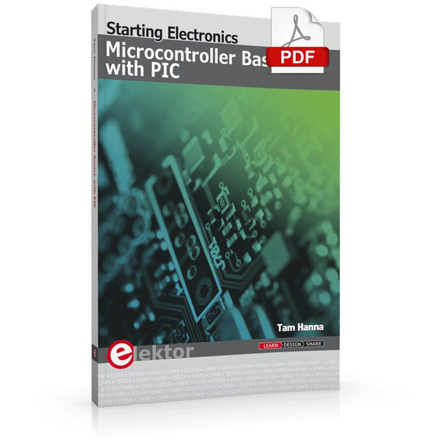
In diesem Buch werden wir uns ausschließlich mit 8-Bit-Mikrocontrollern beschäftigen, und zwar mit Mikrocontrollern der 8-Bit-PIC- und der 8-Bit-AVR-Mikrocontroller-Linien. Bei der PIC-Familie handelt es sich dabei um PIC10, PIC12, PIC16 und PIC18; bei der AVR-Familie um ATtiny, ATmega und ATxmega. Die vorgestellten 8-Bit-Chips sind für sehr viele Anwendungen vollkommen ausreichend und preislich auch attraktiv.
Durch die Lektüre des Buches erhalten Sie ein fundiertes Wissen über die genannten 8-Bit-Mikrocontroller, über ihre Architektur, ihre Pinbelegungen und über ihre Programmierung.
Weil wir uns in diesem Buch mit den Grundlagen der Architektur der PICs und AVRs vertraut machen möchten, werden wir auch für alle PIC- und AVR-Anwendungen Assembler einsetzen, denn die Assembler-Sprache erlaubt es, die Technik im Detail kennenzulernen. Wenn man wirklich wissen möchte, was sich im Mikrocontroller abspielt, greift man zu Assembler. Damit hat man die beste Gelegenheit, sehr nah an den Kern zu kommen. Und wenn man schon einen Mikrocontroller-Typ kennengelernt und verstanden hat, ist es bei dem nächsten deutlich einfacher, auch wenn er von einem anderen Hersteller kommt. Bei anderen Programmiersprachen bleibt die Technik immer ziemlich tief versteckt.
Die Assembler-Beispiele sind so einfach gestaltet, dass sie jeder mit den im Buch aufgezeigten Programmiertechniken erstellen kann. Weil es sich um einfache Beispiele handelt, werden wir sie alle auf einer universellen Lochrasterplatine realisieren. Manche sind auch auf einem Experimentier-Breadboard umsetzbar.
In this book the author presents all essential aspects of microcontroller programming, without overloading the reader with unnecessary or quasi-relevant bits of information. Having read the book, you should be able to understand as well as program, 8-bit microcontrollers.
The introduction to microcontroller programming is worked out using microcontrollers from the PIC series. Not exactly state-of-the-art with just 8 bits, the PIC micro has the advantage of being easy to comprehend. It is offered in a DIP enclosure, widely available and not overly complex. The entire datasheet of the PIC micro is shorter by decades than the description of the architecture outlining the processor section of an advanced microcontroller. Simplicity has its advantages here. Having mastered the fundamental operation of a microcontroller, you can easily enter into the realms of advanced softcores later.
Having placed assembly code as the executive programming language in the foreground in the first part of the book, the author reaches a deeper level with ‘C’ in the second part. Cheerfully alongside the official subject matter, the book presents tips & tricks, interesting measurement technology, practical aspects of microcontroller programming, as well as hands-on options for easier working, debugging and faultfinding.
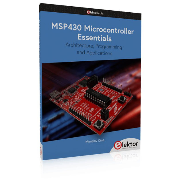
Architecture, Programming and Applications
The MSP430 is a popular family of microcontrollers from Texas Instruments. In this book we will work with the smallest type, which is the powerful MSP430G2553. We will look at the capabilities of this microcontroller in detail, as it is well-suited for self-made projects because it is available in a P-DIP20 package.
We will take a closer look at the microcontroller and then build, step by step, some interesting applications, including a 'Hello World' blinking LED and a nice clock application, which can calculate the day of the week based on the date.
You also will learn how to create code for the MSP microcontroller in assembler. In addition to that, we will work with the MSP-Arduino IDE, which makes it quite easy to create fast applications without special in-depth knowledge of the microcontrollers.
All the code used in the book is available for download from the Elektor website.
Electronic devices increasingly come with glued displays and batteries. And while the adhesive seal serves as a protection against dirt and water, it complicates the opening procedure of the device and hence its repair.
The iOpener: Warm it through, unstick the glue!
With the help of our iOpener, you can easily and quickly loosen adhesive without risking damage to your device due to overheating with a heat gun. Originally designed for opening Apple iPads, the iOpener is just as suitable for Samsung tablets, Sony smartphones, and devices from any other manufacturer who prefers adhesive over screws.
How it works
Heat the iOpener and place it on your device: Simply heat up the iOpener in the microwave or a pot of boiling water and position it on the edge of your device. The heat will soften the adhesive without damaging your gadget so you can insert an opening pick between the display and the case. Repeat this procedure for all glued areas, the iOpener is reusable any number of times.
Use opening tools to remove adhesive residue: With the right tools, you’re now ready to open your device without hassle. The opening picks are sharp-edged enough to cut through the adhesive strips. Complete the opening procedure by prying up the case with an opening tool or lift your display with a suction cup or an iSclack.
A must-have for electronic repairs
The most annoying part of your repair is done, the rest will be almost a cinch. Whether you are a beginner or a professional, the iOpener should be part and parcel of every toolbox worthy of its name.
Your advantages
Loosen adhesive fastenings
Uncomplicated to heat up in the microwave or boiling water
Reusable
Optionally available with opening tools
Contains food grade glycerine
Saves money and the planet
Included
iOpener
Spudger
iFixit Opening Tool
6x iFixit Opening Picks
iFixit Battery Isolation Pick
Plastic Cards
Suction Cup
Angled Tweezers
Plastic bit driver with magnetic bit socket (4 mm), rubberized handle and swivel cap
Precision bits (4 mm)
Phillips #00
Flathead 2.5 mm
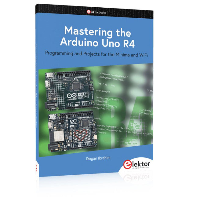
Programming and Projects for the Minima and WiFi
Based on the low-cost 8-bit ATmega328P processor, the Arduino Uno R3 board is likely to score as the most popular Arduino family member, and this workhorse has been with us for many years. Eleven years later, the long-overdue successor, the Arduino Uno R4, was released. It is built around a 48 MHz, 32-bit Arm Cortex-M4 microcontroller and provides significantly expanded SRAM and Flash memory. Additionally, a higher-precision ADC and a new DAC are added to the design. The Uno R4 board also supports the CAN Bus with an interface.
Two versions of the board are available: Uno R4 Minima, and Uno R4 WiFi. This book is about using these new boards to develop many different and interesting projects with just a handful of parts and external modules. All projects described in the book have been fully tested on the Uno R4 Minima or the Uno R4 WiFi board, as appropriate.
The project topics include the reading, control, and driving of many components and modules in the kit as well as on the relevant Uno R4 board, including
LEDs
7-segment displays (using timer interrupts)
LCDs
Sensors
RFID Reader
4x4 Keypad
Real-time clock (RTC)
Joystick
8×8 LED matrix
Motors
DAC (Digital-to-analog converter)
LED matrix
WiFi connectivity
Serial UART
CAN bus
Infrared controller and receiver
Simulators
… all in creative and educational ways with the project operation and associated software explained in great detail.
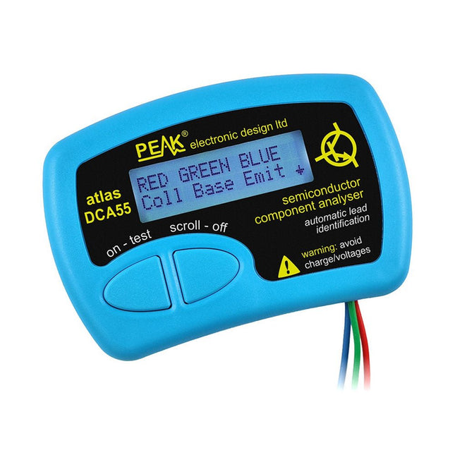
The Peak Atlas DCA55 is great for automatically identifying the type of semiconductor on the test leads as well as the pinout and many other parameters.
Supports transistors MOSFETs, JFETs (gate pin only can be identified), diodes, LEDs and lots more. Automatically identifies type of component, pinout and other important parameters. Now features transistor leakage measurement and Germanium/Silicon identification.
Component Support
Bipolar transistors (NPN/PNP inc Silicon/Germanium)
Darlington transistors (NPN/PNP)
Enhancement mode MOSFETs (N-Ch and P-Ch)
Depletion mode MOSFETs (N-Ch and P-Ch)
Junction FETs (N-Ch and P-Ch). Only gate lead identified
Diodes and diode networks (2 and 3 lead types)
LEDs and bi-colour LEDs (2 lead and 3 lead types)
Low power sensitive Triacs and Thyristors (<5 mA trigger and hold)
Measurements
Part type identification
Pinout identification
BJT current gain (hFE)
BJT base emitter voltage (Vbe)
BJT collector leakage current
MOSFET gate threshold voltage
Diode forward voltage drop (Vf)
Specifications
Analyzer type
Transistors, Diodes, LEDs, MOSFETs, JFETs
Pinout detection
Full pinout (only Gate on JFETs)
Pinout configuration
Connect any way round
Transistor measurements
Vbe, hFE, Iceo
MOSFET measurements
Vgs(on)
Diode measurements
Vf
Probe type
Universal grabber type
Battery
Single AAA cell (supplied). Life typically 1300 ops
Test conditions
Typically 5 mA, 5 V peak
Display type
Alphanumeric LCD (with backlight)
Included
Peak Atlas DCA55 Semiconductor Analyzer
Comprehensive illustrated user guide
Fitted universal hook probes
AAA Alkaline battery
Downloads
Datasheet (EN)
User Guide (EN)
User Guide (IT)
This bundle includes the Red Pitaya STEMlab 125-14 PRO Gen 2 Starter Kit and the new book "Experimenting with Red Pitaya STEMlab Gen 2".
The Red Pitaya STEMlab 125-14 PRO Gen 2 Starter Kit is a powerful and flexible platform for signal processing, data acquisition, and electronic measurement applications. Designed for engineers, developers, researchers, and educators, this kit provides everything required to start building advanced measurement and control systems.
At the core of the kit is the STEMlab 125-14 PRO Gen 2 board, an upgraded and ultra-lightweight development platform. Powered by the Xilinx Zynq-7010 SoC with 512 MB of RAM, it combines FPGA programmability with ARM processing power to enable high-performance instrumentation and custom signal-processing solutions.
The board offers 14-bit ADC and DAC resolution, a 125 MS/s sampling rate, an input range of ±20 V, and up to 60 MHz bandwidth. Its improved low-noise analog front-end, USB-C connectivity, and compact design make it suitable for demanding applications such as RF development, radar systems, photonics research, software-defined radio (SDR), and industrial automation.
The Starter Kit includes all essential accessories for immediate use: a microSD card with preinstalled operating system, power supply, Ethernet cable for remote access, two 100 MHz oscilloscope probes, and SMA-to-BNC adapters for flexible signal connections.
The Red Pitaya STEMlab 125-14 PRO Gen 2 Starter Kit is an excellent platform for rapid prototyping, FPGA development, measurement instrumentation, and advanced electronics experimentation.
Features
14-bit ADC and DAC resolution
125 MS/s sampling rate
±20 V input range
Up to 60 MHz bandwidth
Xilinx Zynq-7010 SoC (FPGA + ARM processor)
512 MB RAM
Low-noise analog front- and back-ends
Applications
RF development and testing
Radar and wireless systems
Software-defined radio (SDR)
Photonics and optical research
Industrial automation and control systems
Signal analysis and instrumentation
Rapid prototyping of electronic measurement systems
Specifications
Processor
Dual-core ARM Cortex-A9
FPGA
AMD Xilinx Zynq-7010 SoC
RAM
512 MB (4 Gb)
Storage
microSD card (up to 32 GB)
Operating System
Linux-based Red Pitaya OS
ADC Resolution
14-bit
DAC Resolution
14-bit
Bandwidth
60 MHz (DC)
Sampling Rate
125 MS/s
Analog Input Channels
2
Analog Output Channels
2
Input Voltage Range
±1 V (LV) / ±20 V (HV)
Input Impedance
1 MΩ / 10 pF
Output Voltage Range
±1 V
Ethernet
1x Gigabit Ethernet (RJ45)
USB
2x USB-C 2.0 (for power and console)
Digital I/O
16x GPIO (3.3 V)
Communication Interfaces
I²C, SPI, UART, CAN
Power Supply
5 V/3 A via USB-C
Dimensions
106.8 x 60.0 x 17.9 mm
Included
1x Red Pitaya STEMlab 125-14 PRO Gen 2 board
2x 100 MHz oscilloscope probes
2x SMA-to-BNC adapters
1x microSD card with preinstalled OS
1x USB-C Power supply
1x Ethernet cable
Downloads
Documentation
Schematics
Book: Experimenting with Red Pitaya STEMlab Gen 2
With this new book, Red Pitaya goes beyond a versatile board. It becomes a powerful laboratory instrument for precision measurement, analysis, and control.
From the fundamentals of electronic project development, monitoring, control, and design to testing, this book walks you step-by-step through everything you need to know to harness the full potential of Red Pitaya hardware and software.
The book presents real-time, FPGA-based projects that are developed on a PC using the Vivado environment, then transferred to the Red Pitaya for execution and testing.
You will learn about enhanced performance, expanded I/O capabilities, improved FPGA features, and advanced connectivity options that open up new frontiers for precision measurement, monitoring, and control in your embedded applications.
Inside the book you will discover:
A deep dive into Red Pitaya architecture and hardware design
Electronic experiments using Red Pitaya for measurement and monitoring
Hands-on projects using the Python programming language
Practical guidance for FPGA programming using Red Pitaya
Red Pitaya FPGA projects using the Verilog HDL under Vivado IDE
Practical design of electronic projects including measurement and testing
Step-by-step examples that bridge theory and real-world implementation
Whether you are designing your own electronic circuits, developing signal analysis tools, or creating real-time control or monitoring systems, this book provides you the knowledge and confidence you need to fully learn and customize the Red Pitaya platform.
This clear acrylic case is the official case for the HackRF One/Pro board. It can replace the standard black plastic case of the HackRF One/Pro.
Assembly Instructions
Use a guitar pick or spudger to extract the HackRF One/Pro circuit board from the black plastic case.
Insert one long screw into each corner of the bottom acrylic panel. Secure each long screw with a short (5 mm) spacer on the opposite side of the panel.
Place the HackRF One/Pro circuit board (facing up) on top of the bottom panel, fitting the ends of the long screws through the corner mounting holes of the circuit board.
Secure the circuit board with one long (6 mm) spacer in each corner.
Place the top acrylic panel on top of the circuit board, aligning the cutouts with the circuit board’s expansion headers.
Secure each corner with a short screw.
Note: Do not overtighten! Hand-tighten only at every step.