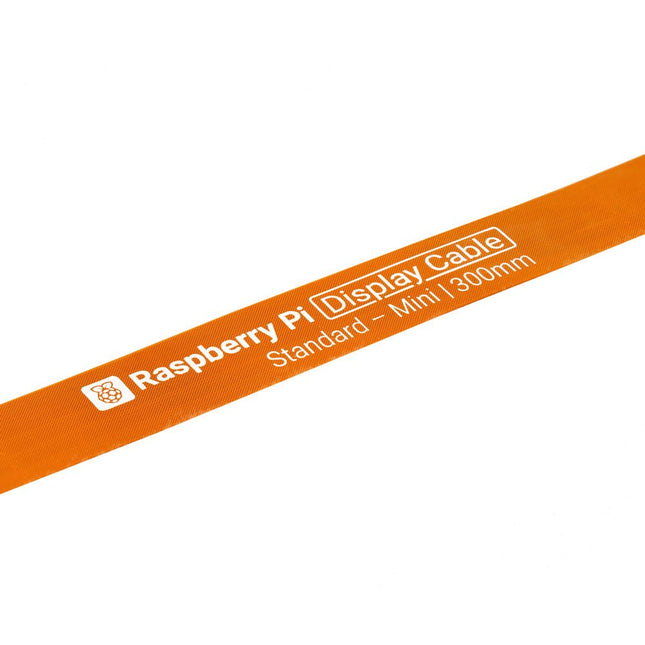
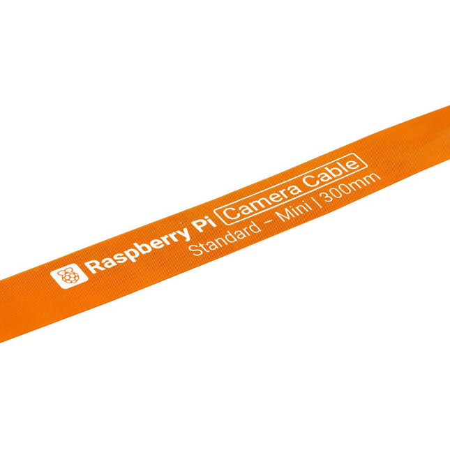
Raspberry Pi 5 provides two four-lane MIPI connectors, each of which can support either a camera or a display. These connectors use the same 22-way, 0.5 mm-pitch “mini” FPC format as the Compute Module Development Kit, and require adapter cables to connect to the 15-way, 1 mm-pitch “standard” format connectors on current Raspbery Pi camera and display products.These mini-to-standard adapter cables for cameras and displays (note that a camera cable should not be used with a display, and vice versa) are available in 200 mm, 300 mm and 500 mm lengths.
Programmierung in Assembler und C am Beispiel der ATtiny-Familie
Dieses Buch bietet einen eingehenden Blick auf die 8-Bit-AVR-Architektur in ATtiny- und ATmega-Mikrocontrollern, hauptsächlich aus der Sicht der Software und der Programmierung. Erforschen Sie die AVR-Architektur unter Verwendung von C und Assembler in Microchip Studio (früher Atmel Studio) mit ATtiny-Mikrocontrollern.
Lernen Sie die Details der internen Funktionsweise von AVR-Mikrocontrollern kennen, einschließlich der internen Register und des Speicherplans von ATtiny-Bausteinen.
Programmieren Sie ATtiny-Mikrocontroller mit einem Atmel-ICE-Programmiergerät/Debugger oder verwenden Sie ein preiswertes Hobby-Programmiergerät oder sogar einen Arduino Uno als Programmiergerät.
Die meisten Code-Beispiele können mit dem Microchip Studio AVR-Simulator ausgeführt werden.
Lernen Sie, Programme für ATtiny-Mikrocontroller in Assembler zu schreiben.
Erfahren Sie, wie Assemblersprache in Maschinencodebefehle umgewandelt wird.
Finden Sie heraus, wie Programme, die in der Programmiersprache C geschrieben wurden, in Assemblersprache und schließlich in Maschinencode umgewandelt werden.
Verwenden Sie den Microchip Studio Debugger in Kombination mit einem Hardware-USB-Programmierer/Debugger, um Assembler- und C-Programme zu testen oder verwenden Sie den Microchip Studio AVR-Simulator.
ATtiny-Mikrocontroller im DIP-Gehäuse werden verwendet, um eine einfache Nutzung auf Breadboards zu ermöglichen.
Erfahren Sie mehr über Timing und Taktimpuls in AVR-Mikrocontrollern mit ATtiny-Bausteinen.
Werden Sie zu einem AVR-Experten mit fortgeschrittenen Debugging- und Programmierfähigkeiten.
Raspberry Pi 5 provides two four-lane MIPI connectors, each of which can support either a camera or a display. These connectors use the same 22-way, 0.5 mm-pitch “mini” FPC format as the Compute Module Development Kit, and require adapter cables to connect to the 15-way, 1 mm-pitch “standard” format connectors on current Raspbery Pi camera and display products.These mini-to-standard adapter cables for cameras and displays (note that a camera cable should not be used with a display, and vice versa) are available in 200 mm, 300 mm and 500 mm lengths.
SPD3000X Series Linear Programmable DC Power Supply has a 4.3 inches TFT LCD display, Supports Programmability and Real Time Wave Display, bringing a new experience to users. It has three isolated outputs: two adjustable channels and one selectable channel from 2.5V, 3.3V, and 5V. It also has output short and overload protect function, and can be used in production and development.
Features
3 independent controlled and isolated output, 32V/3.2A×2, 2.5V/3.3V/5V/3.2A×1, total 220W.
5 digits Voltage, 4 digits Current Display, Minimum Resolution: 1mV/1mA.
Supports panel timing output functions.
4.3 inch true color TFT LCD 480x272 pixel display.
3 kinds of output modes: independent, series, parallel.
100V/120V/220V/230V compatible design to meet the needs of different power grids.
Intelligent temperature-controlled fan, effectively reducing noise.
Clear graphical interface, with the waveform display function
Internal 5 groups of system parameter save/recall, supports data storage space expansion.
Provides PC software: Easypower, supports SCPI, LabVIEW driver.
High-resolution and high-precision output
The highest resolution of 1mV/1mA, provides excellent setting and read back accuracy. This ensures accurate output even with very with small changes in voltage or current. This is impossible for a low resolution power supply.
Series/parallel/independent mode function
Series and parallel function allows two channels combined into one output with more power output capability, extending the application range. Each of 3 channels power can be turned on or off independently and also can be turned all on or all off.
Panel displays the timing output
Through the panel operation, 5 groups of timing settings and output control can be displayed, which provides users a simple power programming function. Also a connection can be made with Siglent’s EasyPower PC software providing a full range of communication and control requirements.
Save/Recall setting parameters
SPD3000X series programmable power supply can save or recall 5 groups of setting parameter in internal storage, also supports external storage expansion. You can easily obtain the settings you needed.
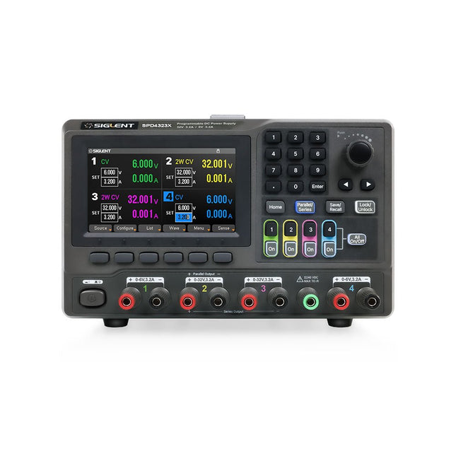
The Siglent SPD4323X is a 4-channel DC Linear Programmable Power Supply equipped with a 4.3-inch TFT-LCD display, friendly human-machine interface, and excellent performance indicators. Real-time waveform display provides engineers with an informative user interface.
SPD4323X offers a total output power of 240 W with a resolution of 1 mV/1 mA. The maximum voltage and current for each channel are as follows:
CH1: 6 V/3.2 A
CH2: 32 V/3.2 A
CH3: 32 V/3.2 A
CH4: 6 V/3.2 A
Features
Rated output power: 240 W
Rated voltage: 32 V, 12 V, 30 V
Up to four high-precision power supplies with independent controllable outputs, supporting CH2 and CH3 series and parallel connections
Clear graphical interface with waveform and timer display modes
5-digit voltage and current display with minimum resolution of 1 mV, 1 mA
Fast output response time: <50us
The high current channel support remote voltage compensation sense function. The maximum compensation voltage is 0.6 V
Overvoltage protection and overcurrent protection or safe and accurate operation
Equipped with a 4.3-inch TFT-LCD display (480 x 272 resolution)
USB and LAN standard communication
USB-GPIB module is optional
Excellent channel density with up to 4 channels in a 3U half rack package
Internal data storage for setups and parameters
Embedded Web Server with instrument communication that doesn’t require software installation
Fully SCPI programming command set support as well as a LabView driver for remote control and system automation
Specifications
SPD4323X
SPD4121X
SPD4306X
Channel Output
CH1: Voltage 0 to 6 V Current 0 to 3.2 ACH2: Voltage 0 to 32 V Current 0 to 3.2 ACH3: Voltage 0 to 32 V Current 0 to 3.2 ACH4: Voltage 0 to 6 V Current 0 to 3.2 A
CH1: Voltage 0 to 15 V Current 0 to 1.5 ACH2: Voltage 0 to 12 V Current 0 to 10 ACH3: Voltage 0 to 12 V Current 0 to 10 ACH4: Voltage 0 to 15 V Current 0 to 1.5 A
CH1: Voltage 0 to 15 V Current 0 to 1.5 ACH2: Voltage 0 to 30 V Current 0 to 6 ACH3: Voltage 0 to 30 V Current 0 to 6 ACH4: Voltage 0 to 15 V Current 0 to 1 A
Resolution
1 mV, 1 mA
1 mV, 1 mA
1 mV, 1 mA
Setting Accuracy
Voltage: ±(0.03% of reading+10) mV, Current: ±(0.3% of reading+10) mA
Voltage: ±(0.03% of reading+10) mV, Current: ±(0.3% of reading+10) mA
Voltage: ±(0.03% of reading+10) mV, Current: ±(0.3% of reading+10) mA
Readback Accuracy
Voltage: ±(0.03% of reading+10) mV, Current: ±(0.3% of reading+10) mA
Voltage: ±(0.03% of reading+10) mV, Current: ±(0.3% of reading+10) mA
Voltage: ±(0.03% of reading+10) mV, Current: ±(0.3% of reading+10) mA
Display
4.3" TFT-LCD 5-digit voltage and current display
4.3" TFT-LCD 5-digit voltage and current display
4.3" TFT-LCD 5-digit voltage and current display
Output power
240 W
285 W
400 W
Included
1x Siglent SPD4323X Power Supply
1x Power cord (EU)
1x Output test cord (3 A)
1x USB cable
1x Quick start guide
Downloads
Datasheet
Manual
Quick start
Fumes released during the soldering process are potentially harmful to health. This solder fume extractor is securely fastened to the work table with a bracket. Thanks to the 3 axes, the solder fume extractor can be positioned perfectly, i.e. directly above the rising solder fumes. The harmful solder fumes are extracted by a powerful but quiet fan and filtered by an activated-carbon filter mat.
Features
Removes solder fumes
Absorbs toxic gases and fumes from brazing operations
Helps reduce the likelihood of headaches, eye irration and neusea
Adjustable absorption angle for accurate placement
Easy replaceable activated carbon filter
High-performance fan
Low noise and long life service
Specifications
Absorption capacity: 1 m³/min (max.)
Power consumption: 23 W
Power supply: 220-240 VAC
Amount of activated carbon filter: 7 g
Maximum absorption weight: 2 g
Dimensions: 220 x 270 x 168 mm (W x H x D)
Weight: 1.4 kg
With this 65 W USB-C PD power supply (with GaN technology) you can start using the FNIRSI HS-01 soldering iron straight away. Of course, you can also use this charger to fast charge your tablets and smartphones via USB-C and USB-A.
Included
65 W USB-C PD GaN Power Supply (EU)
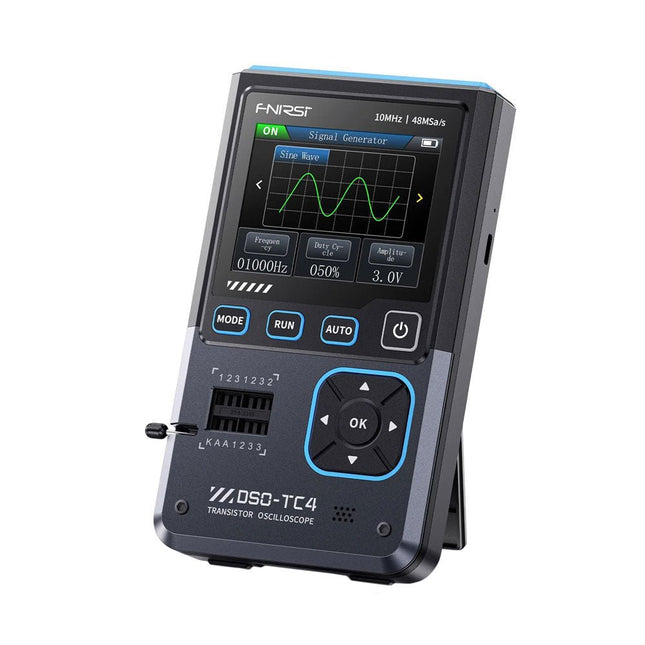
The FNIRDSI DSO-TC4 is a multifunctional transistor oscilloscope that is both comprehensive and practical. It is designed for use in maintenance and R&D applications, integrating an oscilloscope, transistor tester, and signal generator into a single device.
Features
Equipped with a 2.8-inch TFT color screen for a clear and intuitive display
Built-in high-capacity rechargeable lithium battery (1500 mAh) with a standby time of up to 4 hours
Compact and lightweight, ideal for mobile use
Specifications
Oscilloscope
Analog Bandwidth
10 MHz
Real-Time Sampling Rate
48 MSa/s
Input Impedance
1 MΩ
Coupling Mode
AC/DC
Test Voltage Range
1:1 Probe: 80 Vpp (+40 V)
10:1 Probe: 800 Vpp (+400 V)
Vertical Sensitivity
10 mV/div~10 V/div (X1 range)
Vertical Displacement
Adjustable with indication
Time Base Range
50ns~20s
Trigger Mode
Auto/Normal/Single
Trigger Type
Rising edge, Falling edge
Trigger Level
Adjustable with indication
Waveform Freeze
Yes (HOLD function)
Automatic Measurement
Max, Min, Avg, RMS, Vpp, Frequency, Cycle, Duty Cycle
Component Tester
Transistor
Amplification factor "hfe"; Base-Emitter voltage "Ube", Ic/Ie, Collector-Emitter reverse leakage current "Iceo", Ices, Forward voltage drop of protection diode "Uf"
Diode
Forward voltage drop <5 V (Forward voltage drop, Junction capacitance, Reverse leakage current)
Zener Diode
0.01~32 V
Reverse Breakdown Voltage (K-A-A Test Area)
Field-Effect Transistor (FET)
JFET: Gate capacitance "Cg", Drain current Id under "Vgs", Forward voltage drop of protection diode "Uf"
IGBT: Drain current Id under Vgs, Forward voltage drop of protection diode Uf
MIOSTET: Threshold voltage "Vt", Gate capacitance "Cg", Drain-Source resistance "Rds", Forward voltage drop of protection diode "Uf"
Unidirectional SCR
Trigger voltage <5V, Gate level (Gate voltage)
Bidirectional SCR
Trigger current <6mA (Gate voltage)
Capacitor
25pF~100mF, Capacitance value, Loss factor "Vloss"
Resistor
0.01Ω~50MΩ
Inductor
10μH~1000μH, DC resistance
DS18B20
Temperature sensor, Pins: GND, DQ, VDD
DHT11
Temperature and humidity sensor, Pins: VDD, DATA, GND
Signal Generator
Output Waveform
Supports 13 waveform outputs
Waveform Frequency
0-50 KHz
Square Wave Duty Cycle
0-100%
Waveform Amplitude
0.1-3.0 V
General
Display
2.8-inch TFT color screen
Backlight
Brightness adjustable
Power Supply
USB-C (5 V/1 A)
Battery
3.7 V/1500 mAh
Languages
English, German, Spanish, Portuguese, Russian, Chinese, Japanese, Korean
Dimensions
90 x 142 x 27.5 mm
Weight
186 g
Included
1x FNIRSI DSO-TC4 (3-in-1) Oscilloscope (10 MHz)
1x P6100 Oscilloscope probes (10X)
1x Alligator clip probe
3x Test hooks
1x Adapter
1x USB-C charging cable
1x Manual
Downloads
Manual
Firmware V0.0.7 (+V1.0.9)
The SEQURE T55 Smart Mini Temperature Adjustable Soldering Hot Plate is a compact and efficient tool designed for precise preheating and desoldering tasks. With its adjustable temperature range from 50°C to 280°C (122°F to 536°F), it is suitable for various applications, e.g. cell phone repair, PCB assembly, etc.
Features
Adjustable heating temperature range: 50°C to 280°C (122°F to 536°F)
Equipped with a heat-resistant ceramic temperature sensor, ensuring high-accuracy data measurement under continuous high temperatures.
Automatically stops heating after reaching the preset working time.
Supports PD, QC, and DC (max 25 V).
Intelligent temperature control algorithm for temperature compensation and power adjustment.
128 x 32 resolution OLED display with a built-in buzzer to indicate operating status.
°C/°F conversion
Specifications
Heating Area
55 x 55 mm
Working Temperature
50-280°C (122-536°F)
Max Voltage
25 V
Max Power
95 W
Recommend Voltage
19-25 V
PD Power Supply
PD 20 V ≥3A
Power Supply Modes
PD, QC, DC
Interface
USB-C
Display
128 x 32 OLED
Menu Languages
English, Russian, and Chinese
Dimensions
55 x 60 x 37 mm
Weight
92 g
Included
1x SEQURE T55 Smart Mini Soldering Hot Plate
1x PD 65 W Power Supply (EU)
1x Fast Charging Cable (100 W/5 A)
The Weller WT 1013 soldering station set includes the WT 1 supply unit, the WP 80 soldering iron and the WSR 201 safety rest. It is stackable and thus creates more space in the workplace. With an integrated usage sensor, the soldering tool switches off automatically.
Specifications
Channels
1
Voltage
230 V
Power
95 W
Display
Backlit LCD
Temperature range
50 °C - 450 °C
Temperature stability
±2 °C
Temperature accuracy
±9 °C
Fuse
0.5 A
Equipotential bonding
on
WT compatible
on
ESD-safe
on
Power cable
EMEA
Dimensions
149 x 138 x 101 mm
Weight (approx.)
1.9 kg
The OWON SDS1102 is an affordable benchtop digital oscilloscope that combines solid performance with essential measurement features. This 2-channel oscilloscope offers a 100 MHz bandwidth, a 1 GS/s sampling rate, a 7-inch LCD display, and a 10 kpts memory depth, making it a practical choice for everyday electronics testing, troubleshooting, and education.
The SDS1102 features a simplified trigger system with level and edge triggering, making it easy to capture and analyze common signals. It is designed for applications that do not require deep memory or advanced trigger functions, offering a straightforward and cost-effective solution for basic signal analysis.
Features
Bandwidth: 100 MHz
2 channels
Sample rate: 1 GS/s
Ultra-thin body
7-inch high-res LCD
SCPI and LabVIEW supported
Specifications
Bandwidth
100 MHz
Horizontal Scale (s/div)
5 ns/div – 1000 s/div
Channel
2
Vertical Sensitivity
5 mV/div – 5 V/div (at input)
DC Gain Accuracy
3%
Vertical Resolution (A/D)
8 bits (2 channels simultaneously)
Input
Input Impedance
1 MΩ, 10 pF
Input Coupling
AC, DC, GND
Max Input Voltage
±400 V, CATI, CATII
Passive probes
х1; х10
Probe Attenuation Factor
х1; х10; х100; х1000
Trigger System
Trigger Mode
Auto, Normal, Single
Trigger Type
Edge, Video
Edge Trigger Source
CH1, CH2
Video Trigger
Sampling Type
Real-time
Sample Rate
1 GS/s
Equivalent Sample Rate
No
Wavelength
10K pts
Interpolation
sin(x)/x
Measurement and Mathematical Treatment System
Automatic Measurement
Vpp, Vavg, RMS, Frequency, Period, Vmax, Vmin, Vtop, Vbase, Width, Overshoot, Pre-shootRise time, Fall time, +Width, -Width, +Duty, -Duty, Delay A→B, Delay A→B, area, cycle area
Math Functions
Addition, Subtraction, Multiplication, Division, FFT
General Characteristics
Display type
7" color LCD
Display Resolution
800 x 480
Power
100-240 V, 45-440 Hz, <15 W
Dimensions
301 x 70 x 152 mm
Weight
1.1 kg
Included
1x OWON SDS1102 Oscilloscope
2x Oscilloscope probes
1x Probe adjust
1x Mains power cord
1x USB cable
1x CD-Rom
1x Quick guide
Downloads
Quick Guide
Manual
PC Software
SCPI Commands
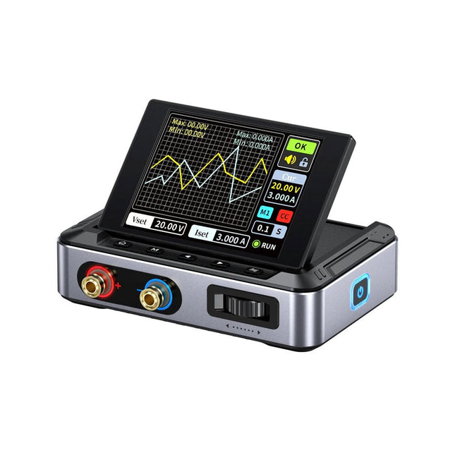
The FNIRSI DPS150 is a high-performance adjustable DC power supply that features a USB-C input interface and multiple power supply modes, allowing precise adjustment of output voltage (0-30 V) and current (0-5 A).
It provides efficient, low-consumption, and stable output, equipped with multiple safety protection functions including overvoltage, overcurrent, overload, overheating, and reverse connection. It can be flexibly applied to serial connection of multiple devices, with rich and user-friendly display and operation, compact and portable design, meeting various application needs.
Features
30 V, 5 A, 150 W variable DC power with 0.01 V, 0.001 A precision, CC/CV modes, and <20 mV ripple to protect sensitive electronics.
Supports PC, QC, and DC inputs with programmable outputs and 6 preset voltage/current settings.
Compatible with 4 mm banana plugs, U-shaped terminals, and copper wires for various equipment.
8 safety mechanisms including overvoltage, current, short circuit, and overheating protection.
2.8-inch HD IPS screen with 90° flip, numerical and curve displays for easy monitoring.
Small, space-saving design for use in labs, repairs, and DIY projects.
Specifications
Input Voltage
5~32 V DC
Input Current
100 mA-5 A
Output Voltage
0-30 V
Output Current
0~5 A
Output Power
0-150 W
Input Way
PD fast charger
QC fast charger
Power bank
DC power adapters
Operating Environment
0-40°C
Load Regulation
0.49%
Full Load Efficiency
96.30%
Display
2.8 inch (320 x 240)
Dimensions
106 x 76 x 28 mm
Weight
178 g
Included
1x DPS150 Power Supply
2x Alligator clip wires (black & red)
1x C2C PD charging cable
1x 100 W PD GaN Adapter (EU)
1x Micro USB cable
1x Manual
Downloads
Manual
Firmware V0.0.1