The FNIRSI TMP-610S is a compact 3-in-1 test instrument combining a True RMS multimeter, 10 MHz oscilloscope, and 50 kHz DDS signal generator. It is designed for electronics troubleshooting, circuit testing, and development in the lab or on the go.
The multimeter offers 60,000-count resolution and supports voltage, current, resistance, capacitance, frequency, temperature, diode, and continuity measurements. The integrated oscilloscope provides real-time waveform analysis at up to 48 MSa/s, while the signal generator supports 13 waveform types with adjustable frequency, amplitude, and duty cycle.
A 3.5-inch IPS touchscreen, smart auto-scan, Bluetooth connectivity for DMM functions, waveform storage, USB export, and a 3,000 mAh rechargeable battery make the TMP-610S a versatile all-in-one tool for electronics professionals and enthusiasts.
Features
3-in-1 Design: DMM + Oscilloscope + Signal Generator
60,000-Count True RMS High-Precision Measurement
10 MHz Oscilloscope with 48 MSa/s Sampling Rate
Bluetooth App Sync (Multimeter Function Only)
3.5-inch Smart Touchscreen with Multiple Display Modes
50 kHz DDS Signal Generator with 13 Waveforms
Built-in Fuse for Easy Replacement
Specifications
Multimeter
Function
Range
Accuracy
DC voltage
600mV/6V/60V/600V/1000V
±(0.03%+5d)
AC voltage
600mV/6V/60V /600V/750V
±(0.3%+15d)
DC current
600uA/6000uA/60mA/600mA
±(0.15%+5d)
6A/10A
±(0.2%+5d)
AC current
600uA/6000uA/60mA/600mA
±(0.5%+15d)
6A/10A
±(0.75%+15d)
Resistance
600Ω/6KΩ/60KΩ/600KΩ/6MΩ
±(0.1%+5d)
60MΩ
±(0.2%+10d)
Capacitance
60nF/600nF/6uF/60uF
±(2.5%+30d)
600uF/6mF/60mF
±(3.5%+30d
Frequency
10 Hz~60 MHz
±(0.01%+5d)
Temperature
-40℃~1000℃
±(1.0%+5℃)
Continuity
0Ω~1KΩ
±(0.2%+5d)
Diode
0V~3.0V, 0Ω~1 Ω
±(1%+5d)
AC frequency response
10KHz
/
Oscilloscope
Real-time Sampling Rate
48 MSa/s
Analog Bandwidth
10 MHz
Input Impedance
1MΩ
Coupling Mode
AC/DC
Test Voltage Range
1:1 Probe - 80Vpp (±40V)
10:1 Probe - 800Vpp (±400V)
Vertical Sensitivity
10mV/div~10V/div
Vertical Displacement
Adjustable with indication
Horizontal Time Base Range
50 ns ~ 20 s
Trigger Mode
Auto, Normal, Single
Trigger Type
Rising, Falling, 50%
Trigger Level
Adjustable with indication
Measurement Parameters
Freq, Period, +Duty, ‒Duty, +Width, ‒Width, Max, Min, P‒P, Amp, RMS, Avg
Persistence
Off / 500ms / 1s / ∞
Cursor Measurement
Yes
Waveform Screenshot Saving
Yes
Signal Generator
Output Waveform
Supports 13 waveform types
Frequency
0~50kHz
Amplitude
0.0V~3.0V
Duty Cycle
0~100%, adjustable for Square and Sawtooth waves
Included
1x FNIRSI TMP-610S Multimeter + Oscilloscope + Signal Generator
1x P6100 Probe
1x Adapter
2x Alligator Clips
2x Multimeter Probes
Probe Accessories
1x Storage Bag
1x USB-C Cable
1x Manual
Downloads
Manual
The ZD-915 is a digital desoldering station with ESD protection and digital display of both the actual and set value on an LCD screen. This desoldering station has high power in a compact and robust housing and makes desoldering easy, because it can be operated with one hand.
The ZD-915 features a soldering gun that houses a filter that catches any sucked material, so you only need to replace the filters to continue. There is also a temperature sensor in the tip so that temperature fluctuations can be quickly absorbed.
Features
The temperature is easily adjusted by simple up/down buttons.
140 W temperature controlled soldering station with adjustable range from 160°C to 480°C.
The desoldering station is designed for lead free desoldering specially.
The side of the station features a typical holder with sponge.
An illuminated power on/off is also loacted on the front.
Specifications
Station
Voltage supply
220-240 V
Power consumption
140 W
Vakuum pressure
600 mm HG
Desoldering Gun
Power consumption
24 V AC 80 WHeat up rating 130 W
Temperature
160-480 °C
Heating element
Ceramic heater
Included
1x ZD-915 Desoldering station
2x Spare soldering tip
3x Cleaning needle for desoldering tips
1x Spare filter for desoldering gun
1x Manual
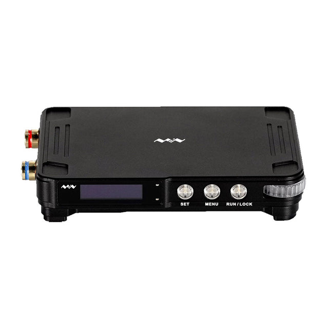
MDP-P906 has a built-in cooling fan, and maximum output power of up to 300 W, which meets a wider range of testing needs and application scenarios. Through 2.4 GHz wireless communication, it can be connected to MDP-M01 Smart Digital Monitor module to realize the free combination of multiple channels of 300 W per channel.
MDP-P906 has the index, stability and reliability comparable to a professional power supply. It can output pure current, and provide powerful functions such as programmable output, timing output, timing control, automatic compensation, boost mode, etc., making itself a real cost-effective, smart and customized programmable linear DC power supply.
MDP-P906 adopts a precision CNC machined aluminum alloy shell, with fine workmanship, novel, mini and beautiful appearance, it completely subverts the rigid image of traditional desktop power supply. With stackable modular design and wireless communication function, MDP-P906 can work independently or paired, both on the workbench, and be carried out for on-site maintenance. MDP-P906 is a perfect solution for electronic engineer, especially field application engineers to meet different needs of power sources.
Built-in silent cooling fan, instant cooling, ensure a stable and efficient output!
Smart linear compensation, constant voltage & constant current
Positive & negative output, series boost, parallel current sharing
Applications
Universal tests and teaching experiments in R&D laboratory
Maintenance of digital products
Property verification and fault diagnosis of devices and circuits
Emergency power supply for model airplanes and vehicles
Power supply testing of RF and microwave circuits or modules
Quality control and quality inspection
Supply purified power for high-accuracy digital-analog hybrid circuits and Hi-Fi audio devices
Specifications
Input
DC 4.2-30 V/14 A (Max)QC 3.0/PD2.0, 20 V/5 A (Max)
Output
0-30 V/0-10 A, 300 W (Max)
Conversion efficiency
95%
Output resolution
10 mV/2 mA, up to 1 mV/1 mA via Display Control module
Output accuracy
0.03%+5 mV0.05%+2 mV
Adjustment rate
Load adjustment rate <±0.01%Power adjustment rate <±0.01%
Ripple and noise
<250 uVrms, 3 mVpp; 2 mArms
Transient response
<4 uS
Safety protections
Input over-voltage, under-voltage, reverse connection protection, output over-current, back-flow protection and over-temperature protection
Others
Automatically shut-down and enter micro-power modeSupport USB firmware upgrade
Dimensions
112 x 66 x 20 mm
Weight
181 g
Included
1x MDP-P906 Digital Power Supply
2x Output Cable
1x User Manual
Downloads
User Manual v1.1
Firmware v1.32
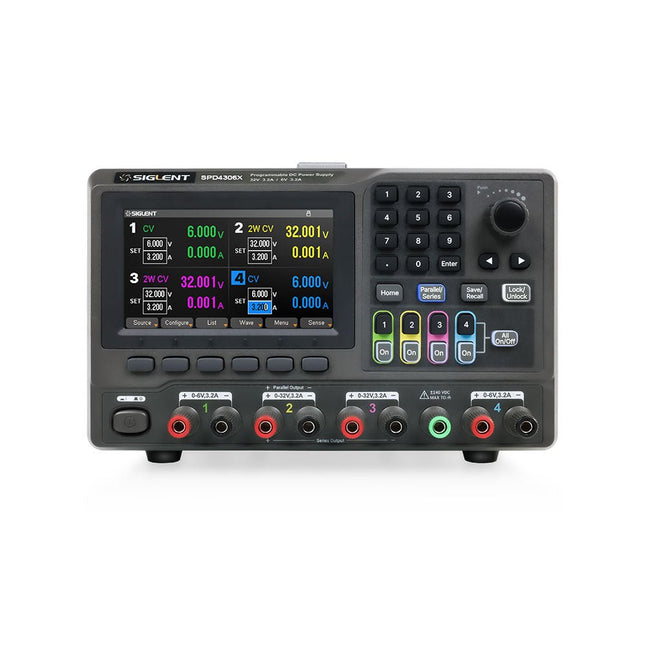
The Siglent SPD4306X is a 4-channel DC Linear Programmable Power Supply equipped with a 4.3-inch TFT-LCD display, friendly human-machine interface, and excellent performance indicators. Real-time waveform display provides engineers with an informative user interface.
SPD4306X offers a total output power of 400 W with a resolution of 1 mV/1 mA. The maximum voltage and current for each channel are as follows:
CH1: 15 V/1.5 A
CH2: 30 V/6 A
CH3: 30 V/6 A
CH4: 15 V/1 A
Features
Rated output power: 400 W
Rated voltage: 32 V, 12 V, 30 V
Up to four high-precision power supplies with independent controllable outputs, supporting CH2 and CH3 series and parallel connections
Clear graphical interface with waveform and timer display modes
5-digit voltage and current display with minimum resolution of 1 mV, 1 mA
Fast output response time: <50us
The high current channel support remote voltage compensation sense function. The maximum compensation voltage is 0.6 V
Overvoltage protection and overcurrent protection or safe and accurate operation
Equipped with a 4.3-inch TFT-LCD display (480 x 272 resolution)
USB and LAN standard communication
USB-GPIB module is optional
Excellent channel density with up to 4 channels in a 3U half rack package
Internal data storage for setups and parameters
Embedded Web Server with instrument communication that doesn’t require software installation
Fully SCPI programming command set support as well as a LabView driver for remote control and system automation
Specifications
SPD4323X
SPD4121X
SPD4306X
Channel Output
CH1: Voltage 0 to 6 V Current 0 to 3.2 ACH2: Voltage 0 to 32 V Current 0 to 3.2 ACH3: Voltage 0 to 32 V Current 0 to 3.2 ACH4: Voltage 0 to 6 V Current 0 to 3.2 A
CH1: Voltage 0 to 15 V Current 0 to 1.5 ACH2: Voltage 0 to 12 V Current 0 to 10 ACH3: Voltage 0 to 12 V Current 0 to 10 ACH4: Voltage 0 to 15 V Current 0 to 1.5 A
CH1: Voltage 0 to 15 V Current 0 to 1.5 ACH2: Voltage 0 to 30 V Current 0 to 6 ACH3: Voltage 0 to 30 V Current 0 to 6 ACH4: Voltage 0 to 15 V Current 0 to 1 A
Resolution
1 mV, 1 mA
1 mV, 1 mA
1 mV, 1 mA
Setting Accuracy
Voltage: ±(0.03% of reading+10) mV, Current: ±(0.3% of reading+10) mA
Voltage: ±(0.03% of reading+10) mV, Current: ±(0.3% of reading+10) mA
Voltage: ±(0.03% of reading+10) mV, Current: ±(0.3% of reading+10) mA
Readback Accuracy
Voltage: ±(0.03% of reading+10) mV, Current: ±(0.3% of reading+10) mA
Voltage: ±(0.03% of reading+10) mV, Current: ±(0.3% of reading+10) mA
Voltage: ±(0.03% of reading+10) mV, Current: ±(0.3% of reading+10) mA
Display
4.3" TFT-LCD 5-digit voltage and current display
4.3" TFT-LCD 5-digit voltage and current display
4.3" TFT-LCD 5-digit voltage and current display
Output power
240 W
285 W
400 W
Included
1x Siglent SPD4306X Power Supply
1x Power cord (EU)
1x Output test cord (3 A)
1x USB cable
1x Quick start guide
Downloads
Datasheet
Manual
Quick start
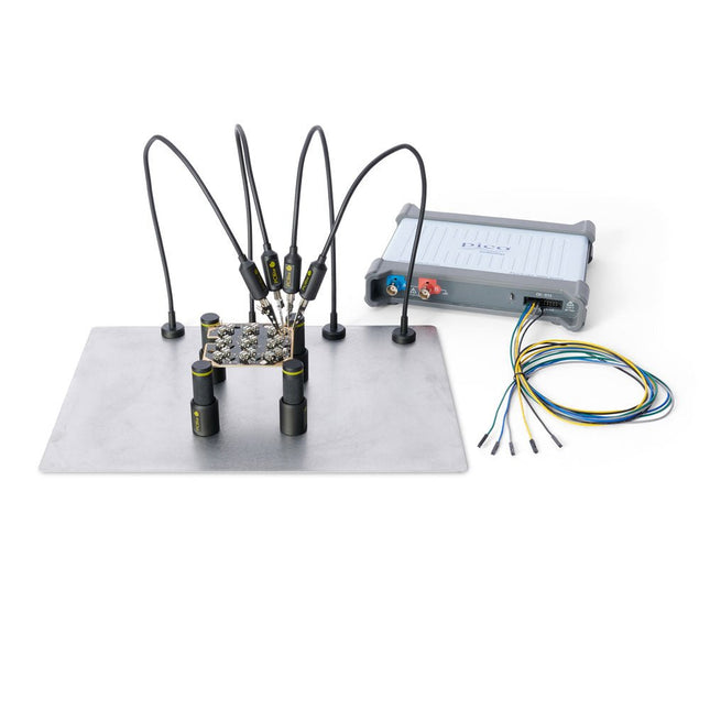
The minimalist design and the spring loaded test needle makes it possible to simultaneously measure on fine pitch components and nearby signals.
The probe is steady but yet flexible made for instant measurements or total hands-free operations together with your multimeter, logic analyzer or preferred tool.
The dual pin header connector fits directly on a 2.54 mm (0.100”) connector.
The SP10 comes with a powerful magnet in the base, as for all PCBite probes and holders which makes the probe easy to place and reposition.
Included
4x PCBite holder
1x Large base plate (A4)
4x PCBite probe with pin tipped test needle
4x Extra crown tipped test needle
1x Set of yellow insulation washers
5x Dupont to dupont test wire
2x Banana to dupont test wire
1x Microfiber cloth
Downloads
User Guide
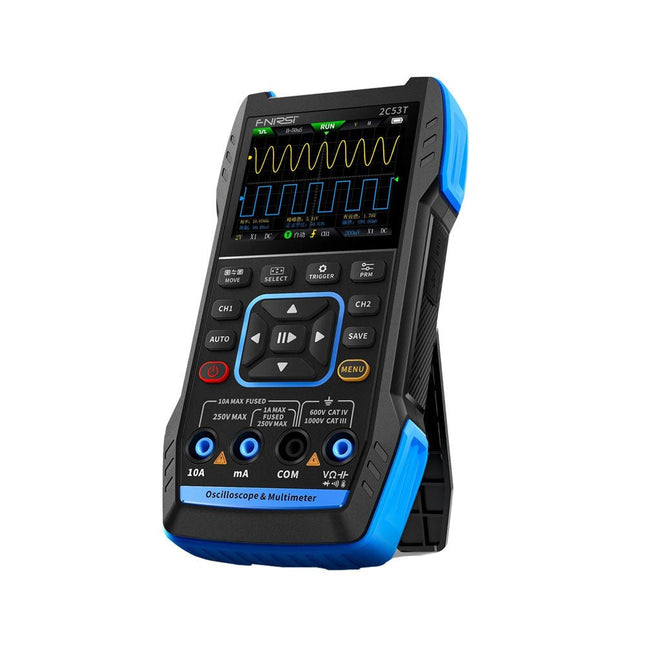
The FNIRSI 2C53T, an enhanced version of its 10 MHz predecessor, is a compact and versatile 3-in-1 device. It combines a dual-channel 50 MHz oscilloscope, a 4.5-digit True RMS multimeter, and a signal generator with 13 waveform types, making it an essential tool for maintenance and research professionals.
Oscilloscope: Features 50 MHz bandwidth, 250 MS/s sampling rate, ±400 V protection, FPGA + ARM + ADC architecture, and waveform saving for analysis.
Multimeter: 4.5-digit True RMS with 19999 counts, supports AC/DC voltage, current, capacitance, resistance, diode, and continuity measurements.
Signal Generator: Outputs 13 signal types up to 50 KHz, with adjustable frequency, amplitude, and duty cycle.
With a 2.8-inch LCD, 3000 mAh battery (6-hour runtime), and a portable design, it delivers powerful functionality in a user-friendly package.
Specifications
Oscilloscope
Channels
2
Analog Bandwidth
50 MHz
Real-time Sampling Rate
250 MS/s
Storage Depth
1 Kpts
Impedance
1 MΩ
Time Base Range
10ns-20s
Vertical Sensitivity
10 mV/div-10 V/div (x1)
Maximum Measured Voltage
±400 V
Trigger Mode
Auto/Normal/Single
Trigger Type
Rising edge, Falling edge
Display Mode
Y-T/Rolling/X-Y
Coupling Method
AC/DC
Persistence
OFF, 500ms, 1s, ∞
Math
8 Basic Operations + FFT
Supported
Waveform Screenshot Save, Export Waveform Image, Cursor Measurement, Infinite Afterglow
Multimeter
DC Voltage
1.9999V/19.999V/199.99V/1000V
±(0.5%+3)
AC Voltage
1.9999V/19.999V/199.99V/750.0V
±(1%+3)
DC Current
19.999mA/199.99mA/1.9999A/9.999A
±(1.2%+3)
AC Current
19.999mA/199.99mA/1.9999A/9.999A
±(1.5%+3)
Resistance
19.999MΩ/1.9999MΩ/199.99KΩ/19.999KΩ
±(0.5%+3)
1.9999KΩ/199.99Ω
±(2.0%+3)
Capacitance
999.9uF/99.99uF/9.999uF/999.9nF/99.99nF/9.999nF
±(2.0%+5)
9.999mF/99.99mF
±(5.0%+20)
Temperature
−55~1300°C (−67~2372°F)
±(2.5%+5)
Continuity Test
Yes
Diode
Yes
Signal Generator
13 Signal Waveforms
Sine wave, rectangular wave, sawtooth wave, half wave, full wave, positive step wave, reverse step wave, exponential rise, exponential fall, DC, multi-audio, Sinker pulse, Lorentz wave
Output Frequency
0-50 KHz
Output Amplitude
0-3 V
Output Duty Cycle
0-100%
General
Display
2.8" HD color screen
Resolution
320 x 240
Charging
USB-C (5 V/1 A)
Battery
3000 mAh Lithium battery
Standby Time
6 hours
Languages
English, Chinese
Dimensions
167 x 89 x 35 mm
Weight
300 g
Differences New vs Old Version
Model
2C53T Upgrade
2C53T Predecessor
Bandwidth
50 MHz
10 MHz
Display Mode
Y-T/Rolling/X-Y
Y-T/Rolling
Math
8 Basic Operations + FFT
N/A
Cursor Function
Yes
N/A
XY Lissau Graph
Yes
N/A
Afterglow Function
Yes
N/A
Multimeter Accuracy
19999 Counts
9999 Counts
Signal Generator
50 KHz
2 MHz
Included
1x FNIRSI 2C53T Oscilloscope (50 MHz)
2x P6100 Oscilloscope probes (10X)
1x Multimeter probe
1x Alligator clip probe
1x USB-C charging cable
1x Storage bag
1x Manual
Downloads
Manual
Firmware V1.2.0
The Siglent SDM3045X is a 4½ digit digital (66000 counts, sampling rate 150 Sa/s) multimeter incorporating a dual-display and is especially well suited for the needs of high-precision, multifunction and automatic measurement.
With its large 4.3" (10.9 cm) TFT color display (480x272 pixels), the menu navigation is very intuitive to use and very easy to read.
Features
Real 4½ digit (66000 counts) readings resolution
Up to 150 rdgs/s measurement speed
True-RMS AC Voltage and AC Current measuring
1 GB NAND flash size, mass storage configuration files and data files
Built-in cold terminal compensation for thermocouple
With easy, convenient and flexible PC software: EasyDMM
Standard interface: USB Device, USB Host, LAN
USB & LAN remote interfaces support common SCPI command set. Compatible with other popular DMMs on the market.
Application Fields
Research Laboratory
Development Laboratory
Detection and Maintenance
Calibration Laboratory
Automatic Production Test
Measurement Functions
DC Voltage: 600 mV – 1000 V
DC Current: 600 μA – 10 A
AC Voltage: True-RMS, 600 mV – 750 V
AC Current: True-RMS, 60 mA – 10 A
2/4-Wire Resistance: 600 Ω – 100 MΩ
Capacitance: 2 nF – 10000 μF
Continuity Test: Range is fixed at 2 kΩ
Diode Test: Adjustable range is 0-4 V
Frequency Measurement: 20 Hz – 500 KHz
Period Measurement: 2 μs – 0.05 s
Temperature: Support for TC and RTD sensor
Max, Min, Average, Standard Deviation, dBm/dB, Relative Measurement, Pass/Fail, Histogram, Trend Chart
Specifications
DC voltage
200 mV, 2 V, 20 V, 200 V, 1000 V
DC current
200 μA, 2 mA, 20 mA, 200 mA, 2 A, 10 A
AC voltage
True-RMS, 200 mV, 2 V, 20 V, 200 V, 750 V
AC current
True-RMS, 20 mA, 200 mA, 2 A, 10 A
2/4-wire resistance
200 Ω, 2 K, 20 K, 200 K, 2 M, 10 M, 100 MΩ
Capacitance
2 nF, 20 nF, 200 nF, 2 μF, 20 μF, 200 μF, 10000 μF
Connectivity Test
Range fixed 2 KΩ
Diode test
Range fixed 2 V
Frequency
20 Hz ~ 1 MHz
Period
1 μs ~ 0.05 s
Temperature
Support thermocouple, RTD temperature sensor
Maximum input voltage
1000 V
Configuration Interface
USB Device, USB Host, LAN
Included
1x Siglent SDM3065X Multimeter
2x Multimeter Probes
1x Power Cord
1x USB Cable
1x Quick Start Guide
Downloads
User Manual
Datasheet
Remote Manual
Service Manual
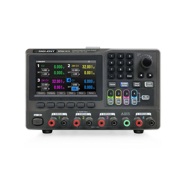
The Siglent SPD4121X is a 4-channel DC Linear Programmable Power Supply equipped with a 4.3-inch TFT-LCD display, friendly human-machine interface, and excellent performance indicators. Real-time waveform display provides engineers with an informative user interface.
SPD4121X offers a total output power of 285 W with a resolution of 1 mV/1 mA. The maximum voltage and current for each channel are as follows:
CH1: 15 V/1.5 A
CH2: 12 V/10 A
CH3: 12 V/10 A
CH4: 15 V/1.5 A
Features
Rated output power: 285 W
Rated voltage: 32 V, 12 V, 30 V
Up to four high-precision power supplies with independent controllable outputs, supporting CH2 and CH3 series and parallel connections
Clear graphical interface with waveform and timer display modes
5-digit voltage and current display with minimum resolution of 1 mV, 1 mA
Fast output response time: <50us
The high current channel support remote voltage compensation sense function. The maximum compensation voltage is 0.6 V
Overvoltage protection and overcurrent protection or safe and accurate operation
Equipped with a 4.3-inch TFT-LCD display (480 x 272 resolution)
USB and LAN standard communication
USB-GPIB module is optional
Excellent channel density with up to 4 channels in a 3U half rack package
Internal data storage for setups and parameters
Embedded Web Server with instrument communication that doesn’t require software installation
Fully SCPI programming command set support as well as a LabView driver for remote control and system automation
Specifications
SPD4323X
SPD4121X
SPD4306X
Channel Output
CH1: Voltage 0 to 6 V Current 0 to 3.2 ACH2: Voltage 0 to 32 V Current 0 to 3.2 ACH3: Voltage 0 to 32 V Current 0 to 3.2 ACH4: Voltage 0 to 6 V Current 0 to 3.2 A
CH1: Voltage 0 to 15 V Current 0 to 1.5 ACH2: Voltage 0 to 12 V Current 0 to 10 ACH3: Voltage 0 to 12 V Current 0 to 10 ACH4: Voltage 0 to 15 V Current 0 to 1.5 A
CH1: Voltage 0 to 15 V Current 0 to 1.5 ACH2: Voltage 0 to 30 V Current 0 to 6 ACH3: Voltage 0 to 30 V Current 0 to 6 ACH4: Voltage 0 to 15 V Current 0 to 1 A
Resolution
1 mV, 1 mA
1 mV, 1 mA
1 mV, 1 mA
Setting Accuracy
Voltage: ±(0.03% of reading+10) mV, Current: ±(0.3% of reading+10) mA
Voltage: ±(0.03% of reading+10) mV, Current: ±(0.3% of reading+10) mA
Voltage: ±(0.03% of reading+10) mV, Current: ±(0.3% of reading+10) mA
Readback Accuracy
Voltage: ±(0.03% of reading+10) mV, Current: ±(0.3% of reading+10) mA
Voltage: ±(0.03% of reading+10) mV, Current: ±(0.3% of reading+10) mA
Voltage: ±(0.03% of reading+10) mV, Current: ±(0.3% of reading+10) mA
Display
4.3" TFT-LCD 5-digit voltage and current display
4.3" TFT-LCD 5-digit voltage and current display
4.3" TFT-LCD 5-digit voltage and current display
Output power
240 W
285 W
400 W
Included
1x Siglent SPD4121X Power Supply
1x Power cord (EU)
1x Output test cord (3 A)
1x USB cable
1x Quick start guide
Downloads
Datasheet
Manual
Quick start
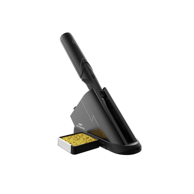
The Miniware Cordless Soldering Station TS1C (with integrated OLED screen and Bluetooth) is an intelligent soldering tool that heats up to 400°C in less than 20 seconds. Thanks to the built-in battery, the wireless soldering pen sits comfortably in the hand and is easy to use.
Features
New high-efficiency supercapacitor energy storage technology, 10,000-level charge and discharge times
Seperate design + true wireless, enjoy wireless soldering experience
BLE4.2 Bluetooth communication technology to realize remote control and setting
Standard PD2 20 V 45 W max power input, up to 36 W soldering power, can continuously solder more than 180 solder joints (0805) with a single full charge
Control station preheating to improve heating efficiency
3 expansion slots for accessories
Control Station
Standard PD2 20 V 45 W max power input, over current safety protection
128x64 pixel OLED screen, display soldering pen status in real time
Control station preheating, improve heating efficiency
Remote control and setting: temperature regulating, menu setting, viewing device info and status, etc.
Work as soldering stand and charging station
3 expansion slots for multiple expandable accessories like sponge slot
Soldering Pen
Built-in 750F high-efficiency energy storage supercapacitor, can be charged via control station (or via its USB Type-C interface in emergency cases)
36 W maximum heating power, can solder more than 180 solder joints (0805) continuously under a single full charge
Compatible with Miniware 3.5 mm audio interface soldering tips (TS80/80P soldering tip series)
Boost mode (holding the button on the pen)
Included
TS1C Soldering pen
TS1C Control station
Soldering tip (TS-B02)
Silicone cable
Sponge slot incl. sponge
Manual
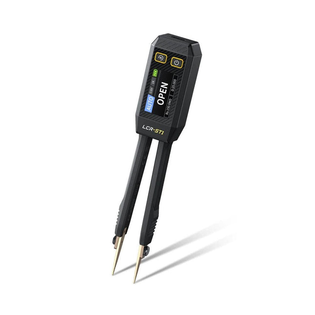
The FNIRSI LCR-ST1 is a compact, multifunctional, and smart LCR tester that supports automatic measurements of resistance, capacitance, inductance, diode testing, and continuity.
Its 1.14-inch color display combined with a convenient magnetic adsorption function enhances ease of use, while the built-in 250 mAh lithium battery ensures long-lasting performance. The device supports three frequency ranges (100 Hz, 1 kHz and 10 kHz) and offers 0.3 V and 0.6 V RMS test levels for versatile testing applications.
The unique tweezer-shaped design of the LCR-ST1 is ideal for delicate tasks in confined spaces and enables fast and accurate testing of electronic components. Its light weight and portable design make it an invaluable tool for both field and laboratory use.
Whether you are an experienced engineer or just starting out in electronics, the LCR-ST1 delivers reliable and accurate measurement results, allowing you to complete your tasks with greater efficiency and precision.
Features
Offers 3 test frequencies (100 Hz, 1 kHz, 10 kHz) and 2 test voltage levels.
Features automatic component identification for faster and more reliable measurements.
High-resolution 1.14-inch color display for clear readouts.
Supports automatic data recording and storage.
The tweezer tips are made from gold-plated brass for enhanced durability and conductivity.
Specifications
Resistance Range
10 mΩ – 10 MΩ
Capacitance Range
1 pF – 22 mF
Inductance Range
1 μh – 10 H
Diode
On voltage 0.7 V
Frequency Test
100 Hz, 1k Hz, 10 KHz
Level Test
0.3 V, 0.6 V RMS
Parameter Display
ESR, D value, Q value, Z value, X value
Display
1.14" HD color screen
Charging Interface
USB-C, 5 V/1 A
Power Supply
Built-in 250 mAh lithium battery
Auto Recognition Measurement
Yes
Replaceable Tweezer Head
Yes
Auto Shutdown
Yes
Data Hold
Yes
History Record
Connect to PC to view and export
Dimensions
28 x 19 x 150 mm
Weight
41 g
Included
1x LCR-ST1 SMD Tweezers
2x Hook Tips
1x Magnetic Patch
1x USB cable
1x Tool bag
1x Manual
Downloads
Manual
Firmware V1.6
Specifications
Dual ARM Cortex-M0+ @ 133 MHz
264 kB on-chip SRAM in six independent banks
Support for up to 16 MB of off-chip Flash memory via dedicated QSPI bus
DMA controller
Fully-connected AHB crossbar
Interpolator and integer divider peripherals
On-chip programmable LDO to generate core voltage
2x on-chip PLLs to generate USB and core clocks
30x GPIO pins, 4 of which can be used as analogue inputs
Peripherals
2x UARTs
2x SPI controllers
2x I²C controllers
16x PWM channels
USB 1.1 controller and PHY, with host and device support
8x PIO state machines
What you'll get
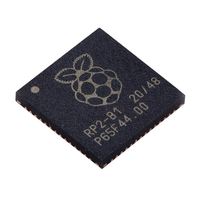
10x bare RP2040 chips
High-quality soldering station with the most important tools and consumables, ideal for universal soldering applications.
Features
1-Channel Power Unit, digital, 70 W
Power unit, 1 channel with soldering iron WEP 70 and safety rest PH 70
70W solder iron with ergonomic handle and providing toolless tip change
ESD safe station, iron and heat-resistant silicon cable for safe handling
Using ET soldering tips
Standby mode and auto setback conserves energy, protects equipment
Password-protected to preserve settings
Specifications
Dimensions: 150 x 120 x 98 mm
Weight: 1.4 kg
Display: Digital LC Display
Temperature range: Adjustable from 100°C - 450°C (200°F - 850°F)
Voltage: 230 V
Channels: 1
Temperature range (depends on tool) °C: 100-450
Temperature range (depends on tool) °F: 200-850
Temperature accuracy °C: Average tip temperature can be „offset“ to +/- 5°C at idle with no load
Temperature accuracy °F: Average tip temperature can be „offset“ to +/- 9°F at idle with no load
Temperature stability °C: ±6
Temperature stability °F: ±10
Heat-up time (ca) in seconds (50-350°C / 120-660°F): 28 sec.
Heating output: 85 W