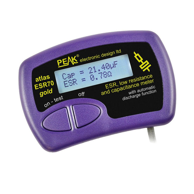
The Peak Atlas ESR70 gold is an enhanced version of the previous Peak Atlas ESR70 Plus. It does everything that the ESR70 Plus did but better.
It now measures capacitance up to 10x faster, and over a wider range, thanks to new test algorithms. The capacitance measurement is also much less influenced by parallel resistances or leakage current thanks to our new Triple-Slope measurement system.
Using the supplied gold plated probes (removable), the Atlas ESR70 gold can measure ESR down to a resolution of 0.01 ohms, up to 40 ohms. It can even measure ESR for capacitors that are in-circuit. Probes are removable, allowing 2 mm compatible probes to be fitted. Audible alerts are produced for various ESR levels allowing you to perform many tests in succession without having to look at the display. The ESR70 automatically takes capacitive reactance into account, so even low value capacitors (down to 0.3 uF) can have the ESR measured accurately.
Features
Uses a single AAA Alkaline cell (included)
Alphanumeric LCD with backlight
Automatic analysis-start when you apply the probes
Automatic capacitor discharge using controlled discharge function
ESR (and low DC resistance) measurement (even in-circuit)
Capacitive reactance automatically taken into account to ensure accurate ESR
Capacitance measurement (if testing out-of-circuit)
Audible alerts for various ESR levels
Extended ESR measurement range up to 40 Ohms
Optional probe alternatives easily fitted
New gold Features
Improved LCD with better backlight
10x faster capacitance measurement for large capacitors
Enhanced user options system
New triple-slope measurement system to vastly reduce the influence of parallel resistance and/or leakage current on capacitance measurements
Much wider capacitance measurement range now 0.3 uF to 90,000 uF (was 1uF to 22,000uF)
Specifications
Analyzer type
ESR and Capacitance
Component types
Capacitors (>0.3 uF)
ESR range
0.00 Ohms to 40.0 Ohms
ESR resolution
From 0.01 Ohms
In-circuit use
ESR only
Capacitance range
0.3 uF to 90000 uF
Battery type
1.5 V Alkaline AAA Cell (supplied). Life typically 1500 ops
Display type
Alphanumeric LCD (with backlight)
Included
Peak Atlas ESR70 gold
Extra-long and extra-flexible test cables (450 mm of Silicone covered cable)
2 mm gold plated plugs and sockets with removeable gold plated crocodile clips
Comprehensive illustrated user guide
AAA Alkaline cell
Downloads
Datasheet (EN)
User Guide (EN)
User Guide (FR)
User Guide (IT)
The Siglent SSA3032X Plus spectrum analyzer is a powerful and flexible tool for RF signal and network analysis. With a frequency range of 3.2 GHz, the analyzer delivers reliable automatic measurements and multiple modes of operation: spectrum analyzer the base, optional functions include RF power measurement, vector signal modulation analysis, reflection measurement, and EMI test.
Applications include broadcast monitoring/evaluation, site surveying, S-parameter measurement, analog/digital modulation analysis, EMI pre-compliance test, research and development, education, production, and maintenance.
Features
Spectrum Analyzer Frequency Range from 9 kHz to 3.2 GHz
–161 dBm/Hz Displayed Average Noise Level (Typ.)
–98 dBc/Hz. @ 10 kHz Offset Phase Noise (1 GHz, Typ.)
Level Measurement Uncertainty <0.7 dB (Typ.)
1 Hz Minimum Resolution Bandwidth (RBW)
Preamplifier (Std.)
Tracking Generator (incl. free of charge)
Analog and Digital Signal Modulation Analysis Mode (opt.)
Reflection Measurement Kit (opt.)
EMI Filter and Quasi-Peak Detector Kit (opt.)
Advanced Measurement Kit (opt.)
10.1-inch Multi-Touch Screen , Mouse and Keyboard supported
Web Browser Remote Control on PC and Mobile Terminals and File Operation
Specifications
SSA3015X Plus
SSA3021X Plus
SSA3032X Plus
SSA3075X Plus
Frequency Range
9 kHz ~ 1.5 GHz
9 kHz ~ 2.1 GHz
9 kHz ~ 3.2 GHz
9 kHz ~ 7.5 GHz
Resolution Bandwidth
1 Hz ~ 1 MHz
1 Hz ~ 1 MHz
1 Hz ~ 1 MHz
1 Hz ~ 3 MHz
Phase Noise
<–99 dBc/Hz
<–98 dBc/Hz
<–98 dBc/Hz
<–98 dBc/Hz
Total Amplitude Accuracy
<1.2 dB
<0.7 dB
<0.7 dB
<0.7 dB
Display Average Noise Level
–156 dBm/Hz
–161 dBm/Hz
–161 dBm/Hz
–165 dBm/Hz
Included
Siglent SSA3032X Plus spectrum analyzer
USB cable
Power cord
Quick start guide
Downloads
Datasheet
Manual
Documentation
Firmware
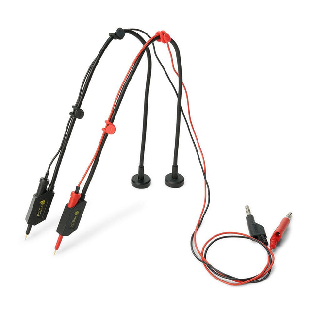
The SQ series of handsfree PCBite probes from Sensepeek are insulated, come with included color-coded cable holders and have a lower point of gravity making them even more stable compared with the original SP series of probes. All the loved features of handsfree measurement, exchangeable fine pitch spring tipped test needle and the minimalistic design is maintained to make traditional sized and handheld probes obsolete.
Features
All handsfree probes from Sensepeek makes instant measurements or long triggering sessions a breeze.
No more soldering wires to connect your probe or complicated tools to setup, just positioning the probe needle on any test point or component in the signal path and release.
Saves time and frustration during development, verification and repairs. The minimalist design and the spring-loaded test needle makes it possible to simultaneously measure on fine pitch components and nearby signals.
Both length and weight of the SQ probes are perfectly balanced to be used with PCBite PCB holders and base plate which is a must for handsfree function.
The probe holder comes with a powerful magnet in the base, as for all PCBite probes and holders which makes the probe easy to place and reposition.
The SQ series of probes can be used handheld without the probe holder as they have an insulated grip but their full potential is used when measuring handsfree.
Included
2x SQ10 probes and pin tipped test needles (red/black)
2x Banana to dupont test wires (red/black)
1x Set of cable holders (red/black)
2x Extra test needles
Downloads
User guide
The Joy-Pi Advanced is a compact and powerful device that allows you to realize your projects quickly and easily. Whether you already have a lot of experience, or next to none, the Joy-Pi Advanced lets you unleash your creativity. Thanks to its compatibility with a wide range of platforms, including Raspberry Pi, Raspberry Pi Pico, Arduino Nano, BBC micro:bit, and NodeMCU ESP32, you can easily and quickly access your preferred platform.
In addition, the Joy-Pi Advanced features more than 30 stations, lessons, and modules, giving you an unlimited variety of ways to get your projects done. With the self-developed learning center, you can not only improve your skills but also create new projects. The learning center offers a wealth of information and tutorials that will guide you step by step through your projects.
Joy-Pi Advanced is characterized in particular by its intelligent switch units, which allow an extended use of the available pins. A total of three switch units are integrated, each equipped with 12 individual switches that provide precise control of the connected sensors and modules. This system solves the well-known problem of limited pin count that occurs with conventional microcontrollers. The switch units allow you to operate a large number of sensors and modules in parallel by switching them on and off individually. This simulates multiple pin assignment, allowing you to exploit the full power of your projects without compromising functionality.
By combining innovative adapter boards and the micro:bit slot, you can achieve seamless compatibility with a wide range of microcontrollers such as Raspberry Pi Pico, NodeMCU ESP32, micro:mit and Arduino Nano. The specially developed adapter boards are designed to perfectly match the respective microcontroller. By plugging the microcontroller onto the appropriate adapter board and then plugging it into the micro:bit slot, the Joy-Pi Advanced quickly and easily becomes compatible with the different microcontrollers. This allows seamless integration of your preferred platform and the ability to combine the strengths of the different microcontrollers in your projects. This way, you can fully focus on your creative projects without worrying about the compatibility of different microcontrollers. The Joy-Pi Advanced simplifies the development process and gives you the possibility to design your projects flexibly and individually.
Features
Highly integrated development platform & learning center
Fast, easy & wireless combination of various sensors & actuators
Installation option for Raspberry Pi 4
Compatible with various microcontrollers
Self-developed, didactic learning platform for Raspberry Pi & Windows
Specifications
Compatible to
Raspberry Pi 4, Arduino Nano, NodeMCU ESP32, BBC micro:bit, Raspberry Pi Pico
Installed sensors, actuators & components
39
Learning platform
Over 40 entries in the know-ledge database, 10 projects, 10 learning tasks, 14 visions
Displays
7-segment display, 16x2 display, 1.8“ TFT display, 0.96" OLED display, 8x8 RGB matrix
Sensors
DS18B20, shock sensor, hall sensor, barometer, sound sensor, gyroscope, PIR sensor, Light barrier, NTC, Light sensor, 6x touch sensor, color sensor, ultrasonic distance sensor, DHT11 temperature & humidity sensor
Control
Joystick, 5x switches, potentiometer, rotary encoder, 4x4 button matrix, relays, PWM fan
Motors
Servo interface, Stepper motor interface, Vibration motor
Measuring & conversion modules
Analog-Digital Converter, Level converter, voltmeter, Variable voltage supply
Other components
RTC real time clock, buzzer, EEPROM memory, infrared receiver, breadboard, RFID reader
Adapter boards
Adapter for NodeMCU ESP32, Arduino Nano & Raspberry Pi Pico, Board connectors for Raspberry Pi & External Boards
Electronic components
Infrared remote control, RFID chip, RFID card, 6x alligator clips, microSD card reader, servo motor, stepper motor, 32 GB microSD card
Components
40x resistors, 3x green LEDs, 3x yellow LEDs, 3x red LEDs, 1x transistor, 5x buttons, 1x potentiometer, 2x capacitors
Other accessories
Screw assortment, screwdriver, accessory storage bag, power supply & power cable, servo mount
Power supply
Built-in power supply: 36 W, 12 V, 3 A Case connector: Small device plug C8
Voltage outputs
12 V, 5 V, 3.3 V, Variable voltage output (2-11 V)
Data buses & signal outputs
I²C, SPI, Analog to digital converter
Battery (RTC)
CR2032
Dimensions
327 x 200 x 52 mm
Included
Raspberry Pi 4 (8 GB RAM)
Downloads
Joy-Pi website
Datasheet
Manual
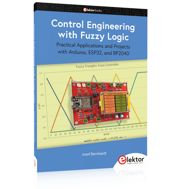
Practical Applications and Project with Arduino, ESP32, and RP2040
Immerse yourself in the fascinating world of control engineering with Arduino and ESP32! This book offers you a practical introduction to classic and modern control methods, including PID controllers, fuzzy logic, and sliding-mode controllers.
In the first part, you will learn the basics of the popular Arduino controllers, such as the Arduino Uno and the ESP32, as well as the integration of sensors for temperature and pH measurement (NTC, PT100, PT1000, and pH sensor).
You will learn how to use these sensors in various projects and how to visualize data on a Nextion TFT display. The course continues with an introduction to actuators such as MOSFET switches, H-bridges, and solid-state relays, which are used to control motors and actuators. You will learn to analyze and model controlled systems, including PT1 and PT2 control.
The book focuses on the implementation of fuzzy and PID controllers for controlling temperature and DC motors. Both the Arduino Uno and the ESP32 are used. The sliding-mode controller is also introduced.
In the second-to-last chapter, you will explore the basics of neural networks and learn how machine learning can be used on an Arduino. In the last chapter, there is a practical example of a fuzzy controller for feeding electricity into the household grid.
This book is the perfect choice for engineers, students, and electronics engineers who want to expand their projects with innovative control techniques.
Elektor GREEN en GOLD leden kunnen deze uitgave hier downloaden.
Nog geen lid? Klik hier om een lidmaatschap af te sluiten.
Audio DSP FX Processor Boarddeel 1: eigenschappen en ontwerp
50 jaar Elektor in het Engels
KiCad 8belangrijkste nieuwe en vernieuwde functies
Elektor @ elektronica 2024electronica Fast Forward 2024, Experts on Stage, Influencer Forums, Live Elektor Lab Talk Shows en meer
Elektor MultiCalculator KitArduino-gebaseerde DHZ-calculator voor elektronici
Goedkope GNSS RTK-systemenmet centimeter-nauwkeurigheid
Printlayout en veiligheidtips voor een veilig en duurzaam ontwerp van uw printen
Opamp-testervoor audio en andere toepassingen
Project-update #4: ESP32-gebaseerde energiemeterenergiemonitoring met MQTT
Real-time spectrumanalyzer met golfgeleider-technologie en multi-interface PC’sAaronia introduceert nieuw productsegment en presenteert eerste prototypes op electronica in München
SMT-spoelenspoelen en ferrieten – selectie gemakkelijk gemaakt
EMC-conformiteit bereiken met EMI-afscherming
De perfecte tool voor elke elektronicaliefhebbereindeloze mogelijkheden met Red Pitaya en 1.000+ Click Boards™
HDI in het middeneen nieuwe kosteneffectieve PCB-poolingservice voor kleine BGA’s
Uitdagingen van DFM-analyse voor flex- en rigid-flex-ontwerpen
Open source-toolsantennesimulator, componentenbeheer, rekenmachine en meer
Elektor infographicprototyping en productie
Uit het leven gegrepenmicrotechnofobie
3D-kerstboomdriedimensionale print met een goedkope 32 bit-microcontroller
Alle begin......houdt nog lang niet op(amp)!
Autonome sensor-node (project-update #1)RTC en voedingsschakelaar
2024: een AI-odysseeeen terugblik op de toekomst
LED-displays met de MAX7219aan de slag met een grandioze chip
Project 2.0correcties, updates en brieven van lezers
Vibrotactiele handschoenendoorbraak voor Parkinson-patiënten
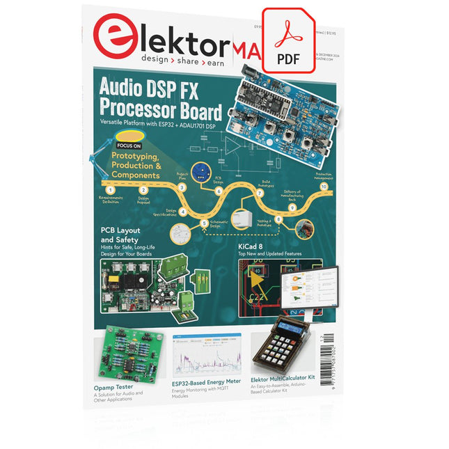
Elektor GREEN and GOLD members can download their digital edition here.
Not a member yet? Click here.
Audio DSP FX Processor BoardPart 1: Features and Design
50 Years of Elektor in English
KiCad 8Top New and Updated Features
Elektor MultiCalculator KitAn Arduino-Based Calculator Kit for Electronic Purposes
Low-Cost GNSS RTK SystemsWith Centimeter-Level Degree of Accuracy
PCB Layout and SafetyHints for a Safe, Long-Life Design of Your Boards
Opamp TesterFor Audio and Other Applications
Project Update #4: ESP32-Based Energy MeterEnergy Monitoring with MQTT
Real-Time Spectrum Analyzer with Waveguide Technology and Multi-Interface PCsAaronia Establishes New Product Segment and Presents First Prototypes at Electronica in Munich
Applications of Ynvisible’s E-paper DisplaysTransform Businesses and Shape the Future
SMT InductorsCoils and Ferrites — Selection Made Easy
Arrow Electronics to Showcase Innovative Technologies at electronica 2024
Using EMI Shielding to Achieve Electromagnetic Compatibility Compliance
The Ultimate Tool for Every Electronics EnthusiastUnlock Endless Possibilities with Red Pitaya and 1,000+ Click Boards™
V-LD1 Distance Radar Module
Siglent Presents Its New Vector Network Analyzer Platform SNA6000A
HDI in the MiddleA New Cost-Effective PCB Pooling Service for Tiny BGAs
Remote Access IoT LabOne and Only Solution for Remote Learning and Development in Embedded Industry
Challenges of DFM Analysis for Flex and Rigid-Flex Design
From Life's ExperienceMicrotechnophobia
3D Christmas TreeA 3D PCB with a Low-Cost, 32-bit Microcontroller
Starting Out in Electronics……Continues with the Opamp!
An Autonomous Sensor Node (Project Update #1)Reducing Idle Power Consumption with External RTC and Power Switch
2024: An AI OdysseyA Look Back at the Future
LED Displays with the MAX7219A Hands-On Approach to a Great Chip
Err-lectronicsCorrections, Updates, and Readers’ Letters
VibroTactile GlovesA Breakthrough for Parkinson’s Patients
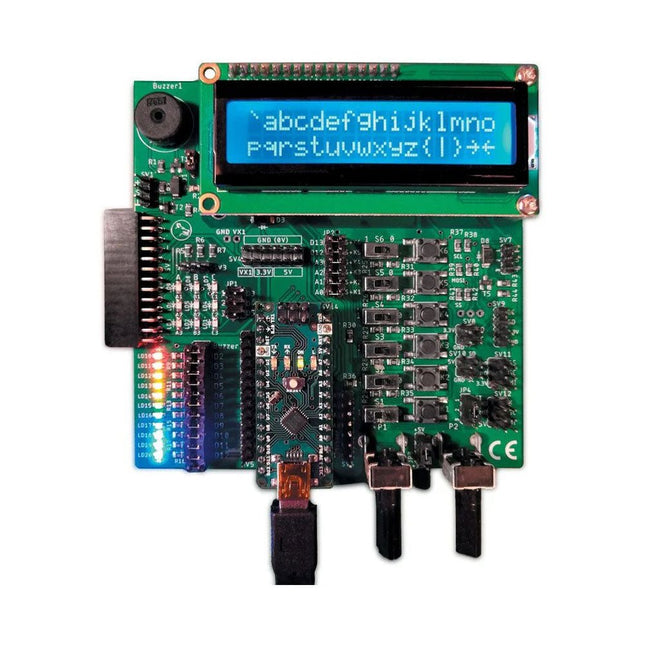
The Elektor Arduino Nano MCCAB Training Board contains all the components (incl. Arduino Nano) required for the exercises in the "Microcontrollers Hands-on Course for Arduino Starters", such as light-emitting diodes, switches, pushbuttons, acoustic signal transmitters, etc. External sensors, motors or assemblies can also be queried or controlled with this microcontroller training system.
Specifications (Arduino Nano MCCAB Training Board)
Power Supply
Via the USB connection of the connected PC or an external power supply unit (not included)
Operating Voltage
+5 Vcc
Input Voltage
All inputs
0 V to +5 V
VX1 and VX2
+8 V to +12 V (only when using an external power supply)
Hardware periphery
LCD
2x16 characters
Potentiometer P1 & P2
JP3: selection of operating voltage of P1 & P2
Distributor
SV4: Distributor for the operating voltagesSV5, SV6: Distributor for the inputs/outputs of the microcontroller
Switches and buttons
RESET button on the Arduino Nano module 6x pushbutton switches K1 ... K6 6x slide switches S1 ... S6 JP2: Connection of the switches with the inputs of the microcontroller
Buzzer
Piezo buzzer Buzzer1 with jumper on JP6
Indicator lights
11 x LED: Status indicator for the inputs/outputs LED L on the Arduino Nano module, connected to GPIO D13 JP6: Connection of LEDs LD10 ... LD20 with GPIOs D2 ... D12
Serial interfacesSPI & I²C
JP4: Selection of the signal at pin X of the SPI connector SV12 SV9 to SV12: SPI interface (3.3 V/5 V) or I²C interface
Switching output for external devices
SV1, SV7: Switching output (maximum +24 V/160 mA, externally supplied) SV2: 2x13 pins for connection of external modules
3x3 LED matrix(9 red LEDs)
SV3: Columns of the 3x3 LED matrix (outputs D6 ... D8) JP1: Connection of the rows with the GPIOs D3 ... D5
Software
Library MCCABLib
Control of hardware components (switches, buttons, LEDs, 3x3 LED matrix, buzzer) on the MCCAB Training Board
Operating Temperature
Up to +40 °C
Dimensions
100 x 100 x 20 mm
Specifications (Arduino Nano)
Microcontroller
ATmega328P
Architecture
AVR
Operating Voltage
5 V
Flash Memory
32 KB, of which 2 KB used by bootloader
SRAM
2 KB
Clock Speed
16 MHz
Analog IN Pins
8
EEPROM
1 KB
DC Current per I/O Pins
40 mA on one I/O pin, total maximum 200 mA on all pins together
Input Voltage
7-12 V
Digital I/O Pins
22 (6 of which are PWM)
PWM Output
6
Power Consumption
19 mA
Dimensions
18 x 45 mm
Weight
7 g
Included
1x Elektor Arduino Nano Training Board MCCAB
1x Arduino Nano
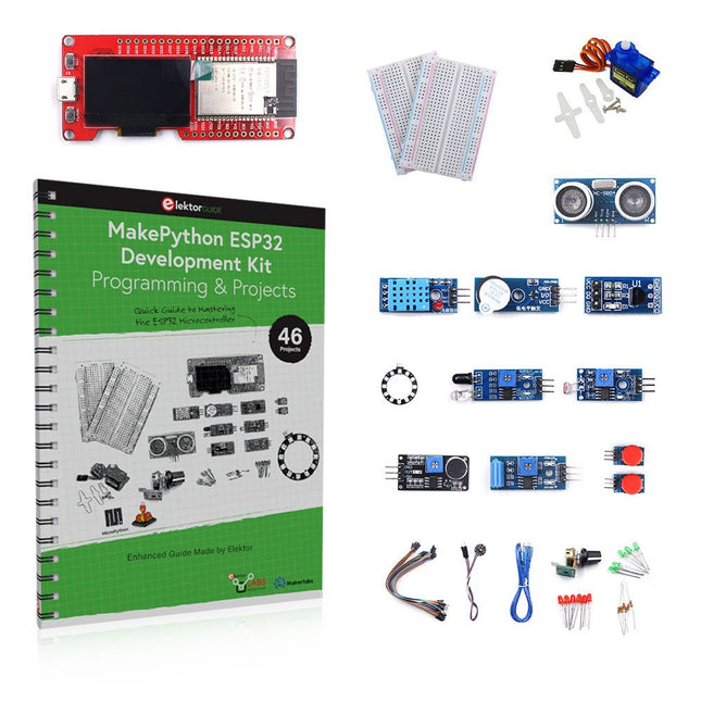
Learn how to use the ESP32 Microcontroller and MicroPython programming in your future projects!
The project book, written by well-known Elektor author Dogan Ibrahim, holds many software- and hardware-based projects especially developed for the MakePython ESP32 Development Kit. The kit comes with several LEDs, sensors, and actuators. The kit will help you acquire the basic knowledge to create IoT projects.
The book’s fully evaluated projects feature all the supplied components. Each project includes a block diagram, a circuit diagram, a full program listing, and a complete program description.
Included in the kit
1x MakePython ESP32 development board with LCD
1x Ultrasonic ranging module
1x Temperature and humidity sensor
1x Buzzer module
1x DS18B20 module
1x Infrared module
1x Potentiometer
1x WS2812 module
1x Sound sensor
1x Vibration sensor
1x Photosensitive resistance module
1x Pulse sensor
1x Servo motor
1x USB cable
2x Button
2x Breadboard
45x Jumper wire
10x Resistor 330R
10x LED (Red)
10x LED (Green)
1x Project book (206 pages)
46 Projects in the Book
LED Projects
Blinking LED
Flashing SOS
Blinking LED – using a timer
Alternately flashing LEDs
Button control
Changing the LED flashing rate using pushbutton interrupts
Chasing-LEDs
Binary-counting LEDs
Christmas lights (random-flashing 8 LEDs)
Electronic dice
Lucky day of the week
Pulsewidth Modulation (PWM) Projects
Generate a 1000-Hz PWM waveform with 50% duty cycle
LED brightness control
Measuring the frequency and duty cycle of a PWM waveform
Melody maker
Simple electronic organ
Servo motor control
Servo motor DS18B20 thermometer
Analog To Digital Converter (ADC) Projects
Voltmeter
Plotting the analog input voltage
ESP32 internal temperature sensor
Ohmmeter
Photosensitive resistance module
Digital To Analog Converter (DAC) Projects
Generating fixed voltages
Generating a sawtooth-wave signal
Generating a triangular-wave signal
Arbitrary periodic waveform
Generating a sinewave signal
Generating accurate sinewave signal using timer interrupts
Using The OLED Display
Seconds counter
Event counter
DS18B20 OLED based digital thermometer
ON-OFF temperature controller
Measuring the temperature and humidity
Ultrasonic distance measurement
Height of a person (stadiometer)
Heart rate (pulse) measurement
Other Sensors Supplied with the Kit
Theft alarm
Sound-activated light
Infrared obstacle avoidance with buzzer
WS2812 RGB LED ring
Timestamping temperature and humidity readings
Network Programming
Wi-Fi scanner
Remote control from the Internet browser (using a smartphone or PC) – Web Server
Storing temperature and humidity data in the Cloud
Low-Power Operation
Using a timer to wake up the processor
The OWON SDS1102 is an affordable benchtop digital oscilloscope that combines solid performance with essential measurement features. This 2-channel oscilloscope offers a 100 MHz bandwidth, a 1 GS/s sampling rate, a 7-inch LCD display, and a 10 kpts memory depth, making it a practical choice for everyday electronics testing, troubleshooting, and education.
The SDS1102 features a simplified trigger system with level and edge triggering, making it easy to capture and analyze common signals. It is designed for applications that do not require deep memory or advanced trigger functions, offering a straightforward and cost-effective solution for basic signal analysis.
Features
Bandwidth: 100 MHz
2 channels
Sample rate: 1 GS/s
Ultra-thin body
7-inch high-res LCD
SCPI and LabVIEW supported
Specifications
Bandwidth
100 MHz
Horizontal Scale (s/div)
5 ns/div – 1000 s/div
Channel
2
Vertical Sensitivity
5 mV/div – 5 V/div (at input)
DC Gain Accuracy
3%
Vertical Resolution (A/D)
8 bits (2 channels simultaneously)
Input
Input Impedance
1 MΩ, 10 pF
Input Coupling
AC, DC, GND
Max Input Voltage
±400 V, CATI, CATII
Passive probes
х1; х10
Probe Attenuation Factor
х1; х10; х100; х1000
Trigger System
Trigger Mode
Auto, Normal, Single
Trigger Type
Edge, Video
Edge Trigger Source
CH1, CH2
Video Trigger
Sampling Type
Real-time
Sample Rate
1 GS/s
Equivalent Sample Rate
No
Wavelength
10K pts
Interpolation
sin(x)/x
Measurement and Mathematical Treatment System
Automatic Measurement
Vpp, Vavg, RMS, Frequency, Period, Vmax, Vmin, Vtop, Vbase, Width, Overshoot, Pre-shootRise time, Fall time, +Width, -Width, +Duty, -Duty, Delay A→B, Delay A→B, area, cycle area
Math Functions
Addition, Subtraction, Multiplication, Division, FFT
General Characteristics
Display type
7" color LCD
Display Resolution
800 x 480
Power
100-240 V, 45-440 Hz, <15 W
Dimensions
301 x 70 x 152 mm
Weight
1.1 kg
Included
1x OWON SDS1102 Oscilloscope
2x Oscilloscope probes
1x Probe adjust
1x Mains power cord
1x USB cable
1x CD-Rom
1x Quick guide
Downloads
Quick Guide
Manual
PC Software
SCPI Commands
This complete ESP32 microcontroller programming course features a textbook, a component kit, hands-on projects, and a comprehensive online course with simulations. It is ideal for step-by-step learning of embedded systems programming in MicroPython using a practical, hands-on approach.
A Practical Introduction to Embedded Systems with the ESP32
This course is designed for people who are new to embedded systems and looking for a structured, example-driven way to get started.
A kit of parts comprising LEDs and resistors, switches, sensors and actuators, displays, a breadboard and wires, and more is included. These are used in the course to illustrate example applications.
No prior experience with Arduino or embedded development is required. Each section features hands-on examples and mini projects designed to reinforce key concepts and inspire deeper exploration. By the end of the course, you’ll be able not only to reproduce the examples but also to build on them with your own ideas and applications.
What Will You Learn?
Microcontroller programming in MicroPython with the ESP32 using the Thonny IDE
Working with Digital I/O, read buttons and encoders, control LEDs and relays
Read analog inputs, voltages, and analog sensors
Generating analog output signals and PWM
Use serial communication like UART, I²C and SPI to control displays and read digital sensors and SD cards
Managing time
Working with interrupts
Real-time sensor input and control via buttons, LEDs, and displays
Control actuators like relays and servo motors
Who Is It For?
Students and self-learners exploring embedded systems
Makers and IoT enthusiasts looking to improve their hardware skills
Educators and trainers seeking ready-to-teach material
What's Inside the Box?
Access to the full course on the Elektor Academy Pro Learning Platform
ESP32 microcontroller board + USB cable
Book: Programming Microcontrollers in MicroPython
Downloadable project files for every module
Component Box:
2× LED, red, 5 mm
LED, green, 5 mm
3× Resistor, 470 Ω, 0.25 W
LDR
Potentiometer, 10 kΩ, linear
Pushbutton
Rotary encoder module
Relay module
DHT22 Humidity & Temperature Sensor
TM1637-compatible 4-digit 7-segment display
MPU-6050 IMU with headers
SSD1306-compatible I²C OLED display
Micro SD card adapter with header
Buzzer
SG90 Micro Servo
ILI9341-compatible SPI 240×320 TFT display
20× Jumper wires
Breadboard
All Programming Courses (and differences in content)
Course
Arduino
Raspberry Pi Pico with Arduino C/C++
ESP32 with Arduino C/C++
Raspberry Pi Pico with MicroPython
ESP32 with MicroPython
Online Course
Access to Arduino Course
Access to Pico with Arduino C/C++ Course
Access to ESP32 with Arduino C/C++ Course
Access to Pico with MicroPython Course
Access to ESP32 with MicroPython Course
Board
Uno R3
Raspberry Pi Pico
ESP32
Raspberry Pi Pico
ESP32
Book
Programming Microcontrollers in C/C++ Using Arduino
Programming Microcontrollers in C/C++ Using Arduino
Programming Microcontrollers in C/C++ Using Arduino
Programming Microcontrollers in MicroPython
Programming Microcontrollers in MicroPython
Kit
40-piece Component Box
40-piece Component Box
40-piece Component Box
40-piece Component Box
40-piece Component Box
Book: Mastering the Arduino Uno R4
Based on the low-cost 8-bit ATmega328P processor, the Arduino Uno R3 board is likely to score as the most popular Arduino family member, and this workhorse has been with us for many years. Eleven years later, the long-overdue successor, the Arduino Uno R4, was released. It is built around a 48 MHz, 32-bit Arm Cortex-M4 microcontroller and provides significantly expanded SRAM and Flash memory. Additionally, a higher-precision ADC and a new DAC are added to the design. The Uno R4 board also supports the CAN Bus with an interface.
Two versions of the board are available: Uno R4 Minima, and Uno R4 WiFi. This book is about using these new boards to develop many different and interesting projects with just a handful of parts and external modules. All projects described in the book have been fully tested on the Uno R4 Minima or the Uno R4 WiFi board, as appropriate.
The project topics include the reading, control, and driving of many components and modules in the kit as well as on the relevant Uno R4 board, including
LEDs
7-segment displays (using timer interrupts)
LCDs
Sensors
RFID Reader
4x4 Keypad
Real-time clock (RTC)
Joystick
8×8 LED matrix
Motors
DAC (Digital-to-analog converter)
LED matrix
WiFi connectivity
Serial UART
CAN bus
Infrared controller and receiver
Simulators
… all in creative and educational ways with the project operation and associated software explained in great detail.
Arduino Uno R4 WiFi
The Arduino Uno R4 is powered by the Renesas RA4M1 32-bit ARM Cortex-M4 processor, providing a significant boost in processing power, memory, and functionality. The WiFi version comes with an ESP32-S3 WiFi module in addition to the RA4M1, expanding creative opportunities for makers and engineers.
The Arduino Uno R4 runs at 48 MHz, which provides a 3x increase over the popular Uno R3. Additionally, SRAM has been upgraded from 2 kB to 32 kB, and flash memory from 32 kB to 256 kB to support more complex projects. Responding to community feedback, the USB port is now USB-C, and the maximum power supply voltage has been raised to 24 V with an enhanced thermal design. The board includes a CAN bus and an SPI port, enabling users to reduce wiring and perform parallel tasks by connecting multiple shields. A 12-bit analog DAC is also provided on the board.
Specifications
Microcontroller
Renesas RA4M1 (ARM Cortex-M4)
USB
USB-C
Programming Port
Pins
Digital I/O Pins
14
Pins
Analog input pins
6
DAC
1
RTC
1
PWM pins
6
Communication
UART
1x
I²C
1x
SPI
1x
Qwiic I²C connector
1x
CAN
1x CAN Bus
Power
Circuit operating voltage
5 V
Input voltage (VIN)
6-24 V
DC Current per I/O Pin
8 mA
Clock speed
Main core
48 MHz
Memory
RA4M1
256 kB Flash, 32 kB RAM
LED Matrix
12 x 8 (96 red LEDs)
Dimensions
68.9 x 53.4 mm
Downloads
Datasheet
Schematics
This bundle contains:
Book: Mastering the Arduino Uno R4 (normal price: €45)
Arduino Uno R4 WiFi (normal price: €30)