
Search results for "logic OR analyzer OR for OR red OR pitaya"
-
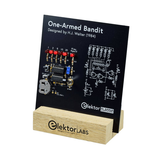
Elektor Labs Elektor One-armed Bandit
Pull Down Lever For Highest Score! This Elektor Circuit Classic from 1984 shows a playful application of CMOS 400x series logic ICs in combination with LEDs, a highly popular combination at the time. The project imitates a spinning-digit type slot machine. The Game To play the game, first agree on the number of rounds. Player 1 actuates the switch lever as long as desired and releases it. The LEDs then show the score which is the sum of the 50-20-10-5 digits lit up. If the Play Again! LED lights, Player 1 has another, “free” round. If not, it’s Player 2’s turn. The players keep tab of their scores, and the highest score wins. Features LEDs Indicate Score Multi-Player and Play Again! Elektor Heritage Circuit Symbols Tried & Tested by Elektor Labs Educational & Geeky Project Through-Hole Parts Only Included Printed Circuit Board All Components Wooden Stand Bill of Materials Resistors (5%, 250 mW) R1,R2,R3,R4 = 100kΩ R5,R6,R7,R8,R9,R10 = 1kΩ Capacitors C1 = 4.7nF, 10%, 50V, 5mm C2 = 4.7μF, 10%, 63V, axial C3,C4 = 100nF, 10 %, 50V, ceramic X7R, 5mm Semiconductors LED1-LED6 = red, 5mm (T1 3/4) IC1 = 74HC4024 IC2 = 74HC132 Miscellaneous S1 = switch, toggle, 21mm lever, SPDT, momentary S2 = switch, tactile, 24V, 50mA, 6x6mm S3 = switch, slide, SPDT IC1,IC2 = IC socket, DIP14 BT1 = PCB-mount CR2032 battery retainer clip Desktop Stand PCB 230098-1 Not included: BT1 = CR2032 coin cell battery
€ 39,95€ 15,98Best Price
-
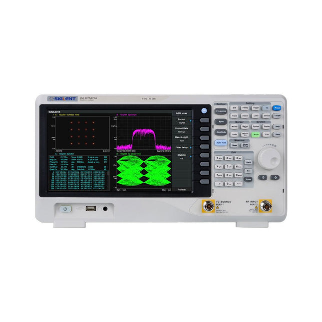
Siglent Siglent SSA3075X Plus Spectrum Analyzer (9 kHz – 7.5 GHz)
The Siglent SSA3075X Plus spectrum analyzer is a powerful and flexible tool for RF signal and network analysis. With a frequency range of 7.5 GHz, the analyzer delivers reliable automatic measurements and multiple modes of operation: spectrum analyzer the base, optional functions include RF power measurement, vector signal modulation analysis, reflection measurement, and EMI test. Applications include broadcast monitoring/evaluation, site surveying, S-parameter measurement, analog/digital modulation analysis, EMI pre-compliance test, research and development, education, production, and maintenance. Features Spectrum Analyzer Frequency Range from 9 kHz to 7.5 GHz –165 dBm/Hz Displayed Average Noise Level (Typ.) –98 dBc/Hz. @ 10 kHz Offset Phase Noise (1 GHz, Typ.) Level Measurement Uncertainty <0.7 dB (Typ.) 1 Hz Minimum Resolution Bandwidth (RBW) Preamplifier (Std.) Tracking Generator (incl. free of charge) Analog and Digital Signal Modulation Analysis Mode (opt.) Reflection Measurement Kit (opt.) EMI Filter and Quasi-Peak Detector Kit (opt.) Advanced Measurement Kit (opt.) 10.1-inch Multi-Touch Screen , Mouse and Keyboard supported Web Browser Remote Control on PC and Mobile Terminals and File Operation Specifications SSA3015X Plus SSA3021X Plus SSA3032X Plus SSA3075X Plus Frequency Range 9 kHz ~ 1.5 GHz 9 kHz ~ 2.1 GHz 9 kHz ~ 3.2 GHz 9 kHz ~ 7.5 GHz Resolution Bandwidth 1 Hz ~ 1 MHz 1 Hz ~ 1 MHz 1 Hz ~ 1 MHz 1 Hz ~ 3 MHz Phase Noise <–99 dBc/Hz <–98 dBc/Hz <–98 dBc/Hz <–98 dBc/Hz Total Amplitude Accuracy <1.2 dB <0.7 dB <0.7 dB <0.7 dB Display Average Noise Level –156 dBm/Hz –161 dBm/Hz –161 dBm/Hz –165 dBm/Hz Included Siglent SSA3075X Plus spectrum analyzer USB cable Power cord Quick start guide Downloads Datasheet Manual Documentation Firmware
€ 7.875,89
-
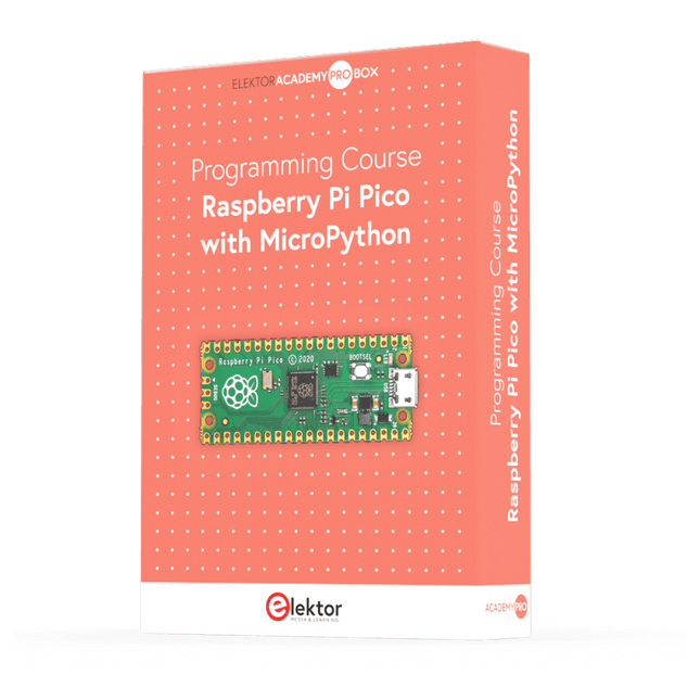
Elektor Academy Pro Raspberry Pi Pico with MicroPython (Programming Course)
This complete Raspberry Pi Pico microcontroller programming course features a textbook, a component kit, hands-on projects, and a comprehensive online course with simulations. It is ideal for step-by-step learning of embedded systems programming in MicroPython using a practical, hands-on approach. A Practical Introduction to Embedded Systems with the Raspberry Pi Pico This course is designed for people who are new to embedded systems and looking for a structured, example-driven way to get started. A kit of parts comprising LEDs and resistors, switches, sensors and actuators, displays, a breadboard and wires, and more is included. These are used in the course to illustrate example applications. No prior experience with Arduino or embedded development is required. Each section features hands-on examples and mini projects designed to reinforce key concepts and inspire deeper exploration. By the end of the course, you’ll be able not only to reproduce the examples but also to build on them with your own ideas and applications. What Will You Learn? Microcontroller programming in MicroPython with the Raspberry Pi Pico using the Thonny IDE Working with Digital I/O, read buttons and encoders, control LEDs and relays Read analog inputs, voltages, and analog sensors Generating analog output signals and PWM Use serial communication like UART, I²C and SPI to control displays and read digital sensors and SD cards Managing time Working with interrupts Real-time sensor input and control via buttons, LEDs, and displays Control actuators like relays and servo motors Who Is It For? Students and self-learners exploring embedded systems Makers and IoT enthusiasts looking to improve their hardware skills Educators and trainers seeking ready-to-teach material What's Inside the Box? Access to the full course on the Elektor Academy Pro Learning Platform Raspberry Pi Pico microcontroller board + USB cable Book: Programming Microcontrollers in MicroPython Downloadable project files for every module Component Box: 2× LED, red, 5 mm LED, green, 5 mm 3× Resistor, 470 Ω, 0.25 W LDR Potentiometer, 10 kΩ, linear Pushbutton Rotary encoder module Relay module DHT22 Humidity & Temperature Sensor TM1637-compatible 4-digit 7-segment display MPU-6050 IMU with headers SSD1306-compatible I²C OLED display Micro SD card adapter with header Buzzer SG90 Micro Servo ILI9341-compatible SPI 240×320 TFT display 20× Jumper wires Breadboard All Programming Courses (and differences in content) Course Arduino Raspberry Pi Pico with Arduino C/C++ ESP32 with Arduino C/C++ Raspberry Pi Pico with MicroPython ESP32 with MicroPython Online Course Access to Arduino Course Access to Pico with Arduino C/C++ Course Access to ESP32 with Arduino C/C++ Course Access to Pico with MicroPython Course Access to ESP32 with MicroPython Course Board Uno R3 Raspberry Pi Pico ESP32 Raspberry Pi Pico ESP32 Book Programming Microcontrollers in C/C++ Using Arduino Programming Microcontrollers in C/C++ Using Arduino Programming Microcontrollers in C/C++ Using Arduino Programming Microcontrollers in MicroPython Programming Microcontrollers in MicroPython Kit 40-piece Component Box 40-piece Component Box 40-piece Component Box 40-piece Component Box 40-piece Component Box
€ 69,95
Members: € 62,96
-
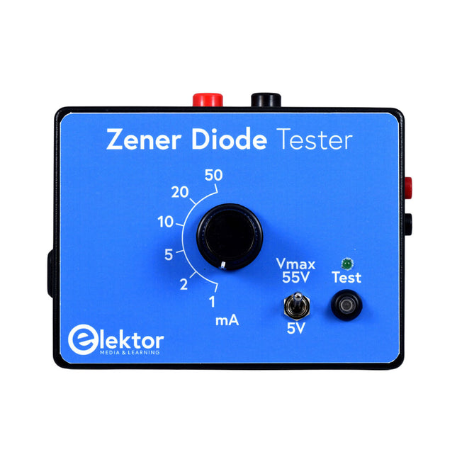
Elektor Zener Diode Tester
The Elektor Zener Diode Tester is essentially a constant-current source that can be switched in steps from 1 to 50 mA. It can be used to test Z-diodes up to a maximum of 54 V. Thanks to a 60-V step-up converter, the device can be powered by the usual 5 to 12 V. The principle of this tester is straightforward. A Z-diode or other DUT (device under test, such as an LED) is biased by an adjustable current source. The voltage across the DUT can be measured with a multimeter. The voltage of most (small) Z-diodes is specified at a current of 5 mA. Depending on the application, the voltage at other currents can also be of interest. That is why six current settings are available: 1, 2, 5, 10, 20, and 50 mA. LEDs are often specified at a current of 20 mA. What can be tested is: Whether a Z-diode is defective (short circuit or high impedance). Whether a Z-diode exhibits the correct Z-voltage. How a Z-voltage changes with different currents. What exact voltage is present at an integrated voltage reference. Whether LEDs in a series chain differ in brightness (hence the 20 mA current). What the current gain is for different base currents in (power) transistors. The kit contains all parts listed in the bill of materials including PCB and enclosure. Specifications Supply voltage 5…12 V/2 A (USB-C) Supply current (Itest = 50 mA) 1.1 A @ 5 V / 412 mA @ 12 V Selectable currents 1, 2, 5, 10, 20, and 50 mA Max. test voltage >54 V @ Itest ≥1 mA Max. output voltage 60 V @ Itest = 0 mA Voltage limit at 5 V 4.5 V @ Itest = 1 mA / 5.18 V @ Itest = 50 mA Enclosure dimensions 110 x 82 x 44 mm PCB size 105.4 x 67.3 mm Connections 4 mm banana sockets for multimeter 2 mm banana sockets for test clips USB-C socket for power supply Included Resistors R1 = 3.3 kΩ, 600 mW, 1% R2 = 0.15 Ω, 1 W, 5%, LS 12.7 mm, ø 3.5 mm R3, R8 = 180 Ω, 600 mW, 1% R4, R6, R16 = 1 kΩ, 600 mW, 1% R5, R19 = 47 kΩ, 600 mW, 1% R7 = 3.9 kΩ, 1 W, 5%, LS 12.7 mm, ø 3.5 mm R9, R10, R12 = 10 kΩ, 600 mW, 1% R11, R13 = 100 Ω, 600 mW 1% R14 = 249 Ω, 600 mW, 1% R15 = 499 Ω, 600 mW, 1% R17 = 2.49 kΩ, 250 mW, 1% R18 = 4.99 kΩ, 250 mW, 1% Capacitors C1 = 470 uF / 35 V, 20%, Ir = 1.86 A, ø 12.5 mm, LS 5 mm, ESR = 0.038 Ω (Panasonic EEUTP1V471) C2 = 1 uF / 100 V, 10%, X7R, LS 5 mm C3 = 2.2 nF / 50 V, 10%, X7R, LS 5 mm C4, C7 = 100 nF / 100 V, 10%, X7R, LS 5 mm C5 = 100 uF / 100 V, 20%, ø 14 mm max., LS 5 mm C6 = 1 nF / 100 V, 10%, X7R, LS 5 mm Inductor L1 = 100 uH, Irms = 2.4 A, Isat = 3.5 A, 0.09 Ω, radial, pitch 2.5/5/10 mm, ø 14 mm max. (Kemet SBC8-101-242) Semiconductors D1 = MUR120G, DO-41 D2, D4 = STPS3150RL, DO-201AD D3 = Z-diode, 18 V, 1.3 W (BZX85C18) D5 = Z-diode, 5.1 V, 0.5 W (1N5231B) LED1 = LED in pushbutton S1 LED2 = LED, green, 3 mm IC1 = MC34063, DIP-8 IC2 = LM4040BIZ-5.0/NOPB, TO-92 (TO-226AA-3) IC3 = TL051CP, DIP-8 T1 = BC327.25, TO-92 T2 = STP40NF10L, TO-220 T3 = IRF9510PBF, TO-220 T4 = 2N7000, TO-92 Others K1, K2, S1, S3 = 2-way screw terminal block, LS 3.5 mm, max. 1.5 mm² connected to K1 = USB-C socket, 30 V/3 A, chassis mounted, wired, 9 x 16 mm connected to K2 = Banana Connector, 2 mm, Socket, 60 VDC, Panel Mount, red (Multicomp 24.102.1) connected to K2 = Banana Connector, 2 mm, Socket, 60 VDC, Panel Mount, black (Multicomp 24.102.2) Test clip, red, 30 VAC/60 VDC (Hirschmann 931467101) Test clip, black, 30 VAC/60 VDC (Hirschmann 931467100) S1 = Pushbutton, panel mount, SPST-NO, 30 DC/100 mA, with red LED S2 = Rotary Switch, 6 position, 2 pole, 30°, 250 V/150 mA S3 = Toggle switch, panel mount, SPDT, solder lugs, 28 VDC T2, T3 = Heat sink, 15°C/W, FK 214 SA-CB Enclosure Hammond 1591XXSSBK, ABS, 110 x 82 x 44 mm Knob for S2, round shaft 6 mm, ø 21 mm, with indicator line (Multicomp CP-LB21-6-6D) 4 x Self-tapping screw #4-1/4", carbon steel, pan head Banana plug, red, 2 mm, 60 VDC (Multicomp 25.205.1) Banana plug, black, 2 mm, 60 VDC (Multicomp 25.205.2) Banana socket, black 4 mm, panel mount Banana socket, red 4 mm, panel mount for LED1, LED2 = Pin header, 1 x 2, vertical, pitch 2.54 mm for LED1, LED2 = Pin socket, 1 x 2, vertical, pitch 2.54 mm for T2, T3 = M3 screw, 10 mm, steel, pan head 2 x M3 washer, plain, steel 4 x M3 nut for IC1, IC3 = DIP-8 socket Wire, black, 0.25 mm² (24 AWG), stranded 14 x 0.15 mm, 1 m Wire, red, 0.25 mm² (24 AWG), stranded 14 x 0.15 mm, 1 m PCB 250772-1 v1.1 Links Article Elektor Labs
€ 99,95€ 79,95Best Price
-

Siglent Siglent SSA3015X Plus Spectrum Analyzer (9 kHz – 1.5 GHz)
The Siglent SSA3015X Plus spectrum analyzer is a powerful and flexible tool for RF signal and network analysis. With a frequency range of 1.5 GHz, the analyzer delivers reliable automatic measurements and multiple modes of operation: spectrum analyzer the base, optional functions include RF power measurement, vector signal modulation analysis, reflection measurement, and EMI test. Applications include broadcast monitoring/evaluation, site surveying, S-parameter measurement, analog/digital modulation analysis, EMI pre-compliance test, research and development, education, production, and maintenance. Features Spectrum Analyzer Frequency Range from 9 kHz to 1.5 GHz –156 dBm/Hz Displayed Average Noise Level (Typ.) –99 dBc/Hz. @ 10 kHz Offset Phase Noise (1 GHz, Typ.) Level Measurement Uncertainty <1.2 dB (Typ.) 1 Hz Minimum Resolution Bandwidth (RBW) Preamplifier (Std.) Tracking Generator (incl. free of charge) Analog and Digital Signal Modulation Analysis Mode (opt.) Reflection Measurement Kit (opt.) EMI Filter and Quasi-Peak Detector Kit (opt.) Advanced Measurement Kit (opt.) 10.1-inch Multi-Touch Screen , Mouse and Keyboard supported Web Browser Remote Control on PC and Mobile Terminals and File Operation Specifications SSA3015X Plus SSA3021X Plus SSA3032X Plus SSA3075X Plus Frequency Range 9 kHz ~ 1.5 GHz 9 kHz ~ 2.1 GHz 9 kHz ~ 3.2 GHz 9 kHz ~ 7.5 GHz Resolution Bandwidth 1 Hz ~ 1 MHz 1 Hz ~ 1 MHz 1 Hz ~ 1 MHz 1 Hz ~ 3 MHz Phase Noise <–99 dBc/Hz <–98 dBc/Hz <–98 dBc/Hz <–98 dBc/Hz Total Amplitude Accuracy <1.2 dB <0.7 dB <0.7 dB <0.7 dB Display Average Noise Level –156 dBm/Hz –161 dBm/Hz –161 dBm/Hz –165 dBm/Hz Included Siglent SSA3015X Plus spectrum analyzer USB cable Power cord Quick start guide Downloads Datasheet Manual Documentation Firmware
€ 1.402,39
-
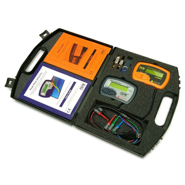
Peak Peak Atlas Pro Pack (LCR45 & DCA75)
This pack contains the LCR45 Passive Component Impedance Meter, great for advanced hobbyists and professionals. It also contains the very popular DCA Pro (model DCA75), fantastic for component identification, pinout identification, detailed characteristic measurement and curve tracing on a PC. Complete with USB cable and software on a USB flash drive. DCA75 Building on the continued success of Peak's existing component identification and analysis instruments, the DCA Pro brings an array of exciting new features for the hobbyist and professional alike. The DCA Pro is an advanced new design that features a graphics display, USB communications, PC Software and an enhanced component identification library. Automatic component type identification Automatic pinout identification (connect any way round) The DCA Pro supports all the components that the popular Peak Atlas DCA55 supports, but adds plenty more. Components supported include: Transistors (including Darlingtons), Silicon and Germanium types. Measures gain, Vbe and leakage MOSFETs, enhancement mode and depletion mode types. Measure on-threshold (at 5 mA) and approx transconductance (for span of 3-5 mA) JFETs, including normally off SiC types. Measures pinch-off voltage (at 1 uA) and approx transconductance (for span of 3-5 mA) IGBTs (insulated gate bipolar transistors). Measures on-threshold (at 5 mA) Diodes and Diode networks LEDs and bicolour LEDs (2 lead and 3 lead types) Zener Diodes with measurement of zener voltage up to 9 V at 5 mA Voltage regulators (measures regulation voltage, drop-out voltage, quiescent current) Triacs and Thyristors that require less than 10 mA of gate current and holding current Stand-alone or with a PC The instrument can be used stand-alone or connected to a PC. Either way, the DCA Pro will automatically identify the component type, identify the pinout and also measure a range of component parameters such as transistor gain, leakage, MOSFET and IGBT threshold voltages, pn characteristics and much more. Curve Tracing When connected to a PC using the supplied USB cable, a range of low current curve-tracing functions can be performed. Various graph types are available, with more to follow: Bipolar transistor output characteristics, IC vs VCE Bipolar transistor gain characteristics, HFE vs VCE Bipolar transistor gain characteristics, HFE vs IC MOSFET and IGBT output function, ID vs VDS MOSFET and IGBT transfer function, ID vs VGS JFET output function, ID vs VDS JFET transfer function, ID vs VGS Voltage regulator, VOUT vs VIN Voltage regulator, IQ vs VIN. PN junction I/V curves, forward and reverse options (for Zener diodes) Curve tracing is performed using test parameters in the range of +/-12 V or +/-12 mA. All curve-tracing data can be instantly pasted into Excel for further graphing and analysis. PC Software is included with the DCA Pro on a Peak USB memory stick. Software designed for Windows 7 and higher (all 32 or 64 bit). LCR45 A great handheld LCR analyzer that can measure the value of your passive component (inductor, capacitor or resistor) and also measure the detailed impedance in a number of modes. The LCR45 offers enhanced measurement resolution (better than 0.1 uH!) whilst also giving you continuous fluid measurements. Additionally, the test frequencies of DC, 1 kHz, 15 kHz and 200 kHz can be set to automatic or manual modes. Supplied with removable gold plated hook probes, battery and user guide. Compatible with standard 2 mm test connectors. Not designed for in-circuit use. Automatic or manual component type selection: Inductor, Capacitor or Resistor Automatic or manual test frequency selection: DC, 1 kHz, 15 kHz and 200 kHz Inductance from 0.1 uH to 10 H Capacitance from 0.1 pF to 10,000 uF Resistance from 0.1 Ohm to 2 MOhm Inductance measurement also shows DC winding resistance Display of "Component type and values", "Complex Impedance", "Magnitude/Phase" and "Admittance" Test frequency displayed for all measurements Typical accuracy of 1.5% for inductors and capacitors (see spec table for details) Typical accuracy of 1% for resistors Test lead complete with gold plated 2 mm plugs and sockets Supplied with removable gold plated hook probes Included LCR45 DCA75 Extra GP23 Battery Extra AAA cell Dual Carry Case
€ 325,49
-
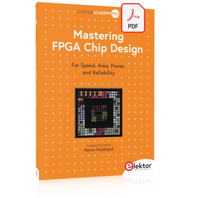
Elektor Digital Mastering FPGA Chip Design (E-book)
For Speed, Area, Power, and Reliability This book teaches the fundamentals of FPGA operation, covering basic CMOS transistor theory to designing digital FPGA chips using LUTs, flip-flops, and embedded memories. Ideal for electrical engineers aiming to design large digital chips using FPGA technology. Discover: The inner workings of FPGA architecture and functionality. Hardware Description Languages (HDL) like Verilog and VHDL. The EDA tool flow for converting HDL source into a functional FPGA chip design. Insider tips for reliable, low power, and high performance FPGA designs. Example designs include: Computer-to-FPGA UART serial communication. An open-source Sump3 logic analyzer implementation. A fully functional graphics controller. What you need: Digilent BASYS3 or similar FPGA eval board with an AMD/Xilinx FPGA. Vivado EDA tool suite (available for download from AMD website free of charge). Project source files available from author’s GitHub site.
€ 32,95
Members: € 29,66
-
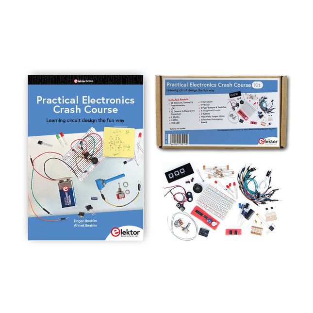
Elektor Bundles Practical Electronics Crash Course (Bundle)
Getting started in electronics is not as difficult as you may think. With this bundle (book + kit of parts), you can explore and learn the most important electrical and electronics engineering concepts in a fun way by doing various experiments. You will learn electronics practically without getting into complex technical jargon and long calculations. As a result, you will be creating your own projects soon. This kit contains the components required to build most of the detailed examples of the book on a breadboard and try them out for real. The kit can, of course, also be used without the book for building other circuits and doing your own experiments. Kit contents 1x 39 Ω, 1 W resistor 1x 47 Ω resistor 1x 180 Ω resistor 1x 330 Ω resistor 3x 1 kΩ resistor 1x 2.2 kΩ resistor 1x 3.9 kΩ resistor 1x 6.8 kΩ resistor 1x 10 kΩ resistor 1x 15 kΩ resistor 1x 22 kΩ resistor 1x 33 kΩ resistor 1x 47 kΩ resistor 1x 56 kΩ resistor 1x 82 kΩ resistor 1x 120 kΩ resistor 1x 680 kΩ resistor 2x 100 kΩ resistor 1x 10 kΩ trimmer 1x 10 kΩ linear potentiometer 1x 100 kΩ linear potentiometer 1x LDR 1x 1 nF ceramic capacitor 2x 10 nF ceramic capacitor 1x 100 nF ceramic capacitor 1x 1 µF, 25 V aluminium electrolytic capacitor 2x 10 µF, 25 V aluminium electrolytic capacitor 1x 100 µF, 25 V aluminium electrolytic capacitor 1x 470 µF, 25 V aluminium electrolytic capacitor 1x 1000 µF, 25 V aluminium electrolytic capacitor 1x RGB LED, Common-Cathode (CC) 1x 1N4148 small signal diode 1x 1N4733A 5.1 V, 1 W Zener diode 3x LED, red 2x BC337 NPN transistor 1x IRFZ44N N-channel MOSFET 2x NE555 timer 1x LM393 comparator 1x 74HCT08 quad AND gate 3x Tactile switch 2x SPDT switch 1x Relay, SPDT, 9 VDC 1x Active buzzer 1x Passive buzzer 50 cm Solid wire, 16 AWG, unjacketed 2x PP3 9 V battery clip 1x Breadboard 20x Jumper wire This bundle contains: Practical Electronics Crash Course Kit (valued at: €45) Book: Practical Electronics Crash Course (normal price: €45)
€ 89,95€ 69,95Best Price
-

Elektor Academy Pro MicroPython for STM32 (Programming Course)
This complete STM32 microcontroller programming course features a textbook, a component kit, hands-on projects, and a comprehensive online course. It is ideal for step-by-step learning of embedded systems programming in MicroPython using a practical, hands-on approach. A Practical Introduction to Embedded Systems with the STM32 This course is designed for people who are new to embedded systems and looking for a structured, example-driven way to get started. A kit of parts comprising LEDs and resistors, switches, sensors and actuators, displays, a breadboard and wires, and more is included. These are used in the course to illustrate example applications. No prior experience with MicroPython or embedded development is required. Each section features hands-on examples and mini projects designed to reinforce key concepts and inspire deeper exploration. By the end of the course, you’ll be able not only to reproduce the examples but also to build on them with your own ideas and applications. What Will You Learn? Microcontroller programming in MicroPython on the STM32 using the Thonny IDE Working with Digital I/O, read buttons and encoders, control LEDs and relays Read analog inputs, voltages, and analog sensors Generating analog output signals and PWM Use serial communication like UART, I²C and SPI to control displays and read digital sensors and SD cards Managing time Working with interrupts Real-time sensor input and control via buttons, LEDs, and displays Control actuators like relays and servo motors Who Is It For? Students and self-learners exploring embedded systems Makers and IoT enthusiasts looking to improve their hardware skills Educators and trainers seeking ready-to-teach material What's Inside the Box? Access to the full course on the Elektor Academy Pro Learning Platform STM32 NUCLEO-F411RE microcontroller board Book: MicroPython for STM32 Downloadable project files for every module Component Box: 2× LED, red, 5 mm LED, green, 5 mm 3× Resistor, 470 Ω, 0.25 W LDR Potentiometer, 10 kΩ, linear Pushbutton Rotary encoder module Relay module DHT22 Humidity & Temperature Sensor TM1637-compatible 4-digit 7-segment display MPU-6050 IMU with headers SSD1306-compatible I²C OLED display Micro SD card adapter with header Buzzer SG90 Micro Servo ILI9341-compatible SPI 240×320 TFT display 20× Jumper wires Breadboard
€ 99,95€ 84,95Best Price
-

Seeed Studio Seeed Studio RF Explorer WSUB1G+ Slim Spectrum Analyzer
The Seeed Studio RF Explorer WSUB1G+ is a powerful, high-performance digital spectrum analyzer covering frequencies from 50 kHz to 1 GHz. The Slim model features a robust design, a more conveniently positioned USB connector on the side, and a larger internal battery capacity. Features Internal LNA amplifier and selectable attenuator Low frequency support from 50 KHz covering LF, MF, HF, VHF and UHF up to 960 Mhz New HELP and SET buttons to improve user interface and configuration selection with 2-clicks Wide band coverage to all popular sub-1 Ghz bands, including FM, TV and DTV, ISM, RFID, GSM, etc. Ideal choice for HAM bands from 160 m to 33 cm Pocket size and light weight Solid metal case Spectrum Analyzer mode with Peak Max and Hold, Normal, Overwrite and Averaging modes High capacity internal Lithium battery for 20hs+ of continuous run, rechargeable by USB Multi-platform Windows/Linux/MacOS Open Source software and API libraries Can be extended with internal Expansion Modules for additional band and functionality Specifications Frequency band: 0.05 MHz – 960 MHz Frequency span: 0.1 MHz – 960 MHz Internal selectable LNA 25 dB gain Internal selectable Attenuator 30 dB Graphics LCD 128 x 64 pixels, great visibility outdoors Support included for Windows, Linux and MacOS X Backlight for great visibility indoor Internal Lithium Ion 1800 mA/h rechargeable battery Standard SMA 50 Ω connector Wideband 144/433 MHz dual band telescopic antenna included UHF 400-900 MHz rubber duck articulated antenna included Amplitude resolution: 0.5 dBm Dynamic range: -125 dBm to 10 dBm Absolute Max input power: +30 dBm Average noise level (typical LNA): -125 dBm Frequency stability and accuracy (typical): ±10 ppm Amplitude stability and accuracy (typical): ±2 dBm Frequency resolution: 1 kHz Resolution bandwidth (RBW): Automatic 2.6 kHz to 600 kHz Included 1x Seeed Studio RF Explorer WSUB1G+ Slim Spectrum Analyzer 1x Mini USB cable 1x Dual band 144/430 MHz Telescopic antenna 1x UHF 400-900 Mhz antenna 1x EVA case
€ 204,49
-
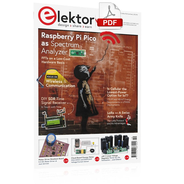
Elektor Digital Elektor September/October 2023 (PDF)
Elektor GREEN and GOLD members can download their digital edition here. Not a member yet? Click here. Raspberry Pi Pico as Spectrum AnalyzerFFTs on a Low-Cost Hardware Basis ±40-V Linear Voltage RegulatorAn Alternative Power Supply for the Fortissimo-100 Power Amplifier… and Others! MCU Wireless Communication Made FlexibleEEPROM Opens Networking Prospects for Wireless MCUs €5,000 up for grabs!Join the STM32 Wireless Innovation Design Contest 2023: An AI OdysseyGetting Started with ChatGPT’s Code Interpreter LoRa, a Swiss Army Knife (1)The LoRa Protocol and Its Advantages Adjustable Current Sink with Integrated Clock GeneratorTest Power Supplies, Voltage Converters and Batteries Two New Arduino UNO R4 Boards: Minima and WiFi Logarithmic PotentiometersThey’re Exponential! Motor Driver Breakout BoardA BoB for a 5 A DC Motor Driver with a 3×3 mm Size From Life’s ExperienceHazardous Electronics Is Cellular the Lowest-Power Option for IoT?LTE-M and NB-IoT Energy Requirements in LPWAN Deployments Wireless Communication in IoT Systems – Using Arduino MKR ModulesThe Right Board for Wi-Fi, LoRa, and Many More Standards AC Losses in Magnetic ComponentsAvoid Hot Inductors! Measurement for Optimal Cloud Deployment Matter Adoption: What does it take to deploy Matter devices? YARD Stick OneA Sub-1 GHz Wireless Test Tool Latching RelaysPeculiar Parts, the Series PIC O’Clock – In Touch with TimeDesigning an SDR Time Signal Receiver Due Diligence DirectiveBusiness as Usual Will Not Do Starting Out in Electronics……Voltage Amplification Infrasound Recorder with the Arduino Pro MiniA Sample Project from Elektor’s “Arduino & Co.” Book Cloud-Based Energy MeterWith ESP32 Module and PZEM-004T Voltage/Current Sensor A Bare-Metal Programming Guide (Part 2)Accurate Timing, the UART, and Debugging Hexadoku
€ 7,50
-
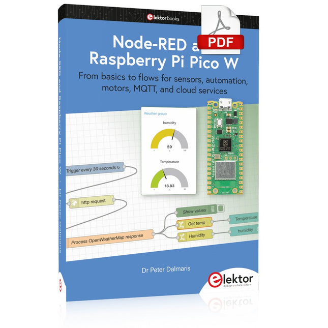
Elektor Digital Node-RED and Raspberry Pi Pico W (E-book)
From basics to flows for sensors, automation, motors, MQTT, and cloud services This book is a learning guide and a reference. Use it to learn Node-RED, Raspberry Pi Pico W, and MicroPython, and add these state-of-the-art tools to your technology toolkit. It will introduce you to virtual machines, Docker, and MySQL in support of IoT projects based on Node-RED and the Raspberry Pi Pico W. This book combines several elements into a platform that powers the development of modern Internet of Things applications. These elements are a flow-based server, a WiFi-enabled microcontroller, a high-level programming language, and a deployment technology. Combining these elements gives you the tools you need to create automation systems at any scale. From home automation to industrial automation, this book will help you get started. Node-RED is an open-source flow-based development tool that makes it easy to wire together devices, APIs, and online services. Drag and drop nodes to create a flowchart that turns on your lights at sunset or sends you an email when a sensor detects movement. Raspberry Pi Pico W is a version of the Raspberry Pi Pico with added 802.11n Wi-Fi capability. It is an ideal device for physical computing tasks and an excellent match to the Node-RED. Quick book facts Project-based learning approach. Assumes no prior knowledge of flow-based programming tools. Learn to use essential infrastructure tools in your projects, such as virtual machines, Docker, MySQL and useful web APIs such as Google Sheets and OpenWeatherMap. Dozens of mini-projects supported by photographs, wiring schematics, and source code. Get these from the book GitHub repository. Step-by-step instructions on everything. All experiments are based on the Raspberry Pi Pico W. A Wi-Fi network is required for all projects. Hardware (including the Raspberry Pi Pico W) is available as a kit. Downloads GitHub
€ 39,95
Members: € 35,96


