
Search results for "fahrzeugdiagnose OR mit OR obd OR 2"
-

Uni-Trend UNI-T UPO1202CS 2-ch Oscilloscope (200 MHz)
UNI-T UPO1202CS is a multifunctional, low-cost 2-channel digital phosphor oscilloscope with 200 MHz bandwidth and 1 GSa/s sampling rate. It can be widely used in the fields of electronic and electrical design, debugging, education and industrial design. UPO1000CS series adopts parallel digital signal processing technology, which greatly improves the data processing speed and waveform capture rate. The original Ultra Phosphor technology can present the cumulative effect of the tested signal as a multi-layered afterglow. Compared with traditional digital storage oscilloscopes, the persistence of digital phosphor oscilloscopes can present three-dimensional waveform data of amplitude, time and signal intensity. Fast Acquire technology can accurately capture abnormal events such as video, jitter, noise and runt signals. Specifications UPO1102CS UPO1202CS Bandwidth 100 MHz 200 MHz Analog channels 2 2 Sampling rate 1 GSa/s 1 GSa/s Storage depth 56 Mpts per channel 56 Mpts per channel Rise time ≤3.5ns ≤1.8ns Capture rate 500,000 wfms/s 500,000 wfms/s Waveform record 100,000 frames 100,000 frames Features 7' WVGA (800 x 480) TFT LCD Ultra Phosphor super fluorescent display effect, up to 256 levels of gray display Support RS232, I²C, SPI, CAN and LIN trigger Innovative RS232, I²C, SPI, CAN and LIN hardware decoding Vertical scale: 1 mV/div-20 V/div Low background noise: <100 μVrms 1M points enhanced FFT function. Support frequency setting, waterfall diagram, detection setting and marker measurement etc 36 kinds of waveform parameters can be automatically measured Rich trigger functions (edge, pulse width, video, slope, runt, overshoot, delay, timeout, duration, setup and hold, Nth edge and pattern trigger) Multi-Scopes support dual-channel independent trigger fluorescence display Multi-channel independent 7-bit hardware frequency counter DVM supports dual-channel independent AC and DC true RMS measurement Waveform arithmetic functions (FFT, +, -, ×, ÷, digital filtering, logic operations, and advanced operations) Rich interfaces: USB Host, USB Device, LAN, EXT Trig, AUX Out (Trig Out, Pass/Fail) Support SCPI programmable instrument standard command Support WEB access and control Downloads Datasheet Programming Manual User's Manual Quick Start Guide Software
€ 369,00
-

Red Pitaya Red Pitaya STEMlab 125-14 PRO Gen 2 Starter Kit (incl. Book)
This bundle includes the Red Pitaya STEMlab 125-14 PRO Gen 2 Starter Kit and the new book "Experimenting with Red Pitaya STEMlab Gen 2". The Red Pitaya STEMlab 125-14 PRO Gen 2 Starter Kit is a powerful and flexible platform for signal processing, data acquisition, and electronic measurement applications. Designed for engineers, developers, researchers, and educators, this kit provides everything required to start building advanced measurement and control systems. At the core of the kit is the STEMlab 125-14 PRO Gen 2 board, an upgraded and ultra-lightweight development platform. Powered by the Xilinx Zynq-7010 SoC with 512 MB of RAM, it combines FPGA programmability with ARM processing power to enable high-performance instrumentation and custom signal-processing solutions. The board offers 14-bit ADC and DAC resolution, a 125 MS/s sampling rate, an input range of ±20 V, and up to 60 MHz bandwidth. Its improved low-noise analog front-end, USB-C connectivity, and compact design make it suitable for demanding applications such as RF development, radar systems, photonics research, software-defined radio (SDR), and industrial automation. The Starter Kit includes all essential accessories for immediate use: a microSD card with preinstalled operating system, power supply, Ethernet cable for remote access, two 100 MHz oscilloscope probes, and SMA-to-BNC adapters for flexible signal connections. The Red Pitaya STEMlab 125-14 PRO Gen 2 Starter Kit is an excellent platform for rapid prototyping, FPGA development, measurement instrumentation, and advanced electronics experimentation. Features 14-bit ADC and DAC resolution 125 MS/s sampling rate ±20 V input range Up to 60 MHz bandwidth Xilinx Zynq-7010 SoC (FPGA + ARM processor) 512 MB RAM Low-noise analog front- and back-ends Applications RF development and testing Radar and wireless systems Software-defined radio (SDR) Photonics and optical research Industrial automation and control systems Signal analysis and instrumentation Rapid prototyping of electronic measurement systems Specifications Processor Dual-core ARM Cortex-A9 FPGA AMD Xilinx Zynq-7010 SoC RAM 512 MB (4 Gb) Storage microSD card (up to 32 GB) Operating System Linux-based Red Pitaya OS ADC Resolution 14-bit DAC Resolution 14-bit Bandwidth 60 MHz (DC) Sampling Rate 125 MS/s Analog Input Channels 2 Analog Output Channels 2 Input Voltage Range ±1 V (LV) / ±20 V (HV) Input Impedance 1 MΩ / 10 pF Output Voltage Range ±1 V Ethernet 1x Gigabit Ethernet (RJ45) USB 2x USB-C 2.0 (for power and console) Digital I/O 16x GPIO (3.3 V) Communication Interfaces I²C, SPI, UART, CAN Power Supply 5 V/3 A via USB-C Dimensions 106.8 x 60.0 x 17.9 mm Included 1x Red Pitaya STEMlab 125-14 PRO Gen 2 board 2x 100 MHz oscilloscope probes 2x SMA-to-BNC adapters 1x microSD card with preinstalled OS 1x USB-C Power supply 1x Ethernet cable Downloads Documentation Schematics Book: Experimenting with Red Pitaya STEMlab Gen 2 With this new book, Red Pitaya goes beyond a versatile board. It becomes a powerful laboratory instrument for precision measurement, analysis, and control. From the fundamentals of electronic project development, monitoring, control, and design to testing, this book walks you step-by-step through everything you need to know to harness the full potential of Red Pitaya hardware and software. The book presents real-time, FPGA-based projects that are developed on a PC using the Vivado environment, then transferred to the Red Pitaya for execution and testing. You will learn about enhanced performance, expanded I/O capabilities, improved FPGA features, and advanced connectivity options that open up new frontiers for precision measurement, monitoring, and control in your embedded applications. Inside the book you will discover: A deep dive into Red Pitaya architecture and hardware design Electronic experiments using Red Pitaya for measurement and monitoring Hands-on projects using the Python programming language Practical guidance for FPGA programming using Red Pitaya Red Pitaya FPGA projects using the Verilog HDL under Vivado IDE Practical design of electronic projects including measurement and testing Step-by-step examples that bridge theory and real-world implementation Whether you are designing your own electronic circuits, developing signal analysis tools, or creating real-time control or monitoring systems, this book provides you the knowledge and confidence you need to fully learn and customize the Red Pitaya platform.
€ 799,00
Best Price
-
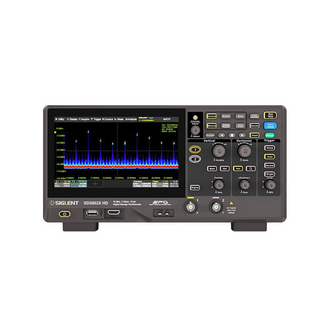
Siglent Siglent SDS822X HD 2-ch Oscilloscope (200 MHz)
The Siglent SDS822X HD digital storage oscilloscope is based on 2 GSa/s, 12-bit Analog-Digital Converters and front ends with excellent noise floor performance. With a 200 MHz bandwidth, and a maximum record length of 100 Mpts, and the capability to analyze 2 analog channels alongside 16 digital channels, the SDS822X HD is perfectly suited for mixed signal analysis. Features 12-bit High Resolution 12-bit Analog-Digital Convertors with sample rate up to 2 GSa/s Front ends with 70 μVrms noise floor @ 200 MHz bandwidth 2/4 analog channels, up to 700 MHz bandwidth SPO technology Waveform capture rate up to 120,000 wfm/s (normal mode), and 500,000 wfm/s (sequence mode) Supports 256-level intensity grading and color temperature display modes. Up to 50 Mpts record length Digital trigger system Intelligent trigger: Edge, Slope, Pulse width, Window, Runt, Interval, Dropout, Pattern, Video (HDTV supported), Qualified, Nth edge, Delay, Setup/Hold time. Serial bus triggering and decoder, supports protocols I²C, SPI, UART, CAN, LIN. Segmented acquisition (Sequence) mode, dividing the maximum record length into multiple segments (up to 80,000), according to trigger conditions set by the user, with a very small dead time between segments to capture the qualifying event. History waveform record (History) function, the maximum recorded waveform length is 80,000 frames. Automatic measurements on 50+ parameters, supports statistics with histogram, track, trend, Gating measurement, and measurements on Math, History and Ref. 4 Math traces (2 Mpts FFT, addition, subtraction, multiplication, division, integration, differential, square root, etc.), supports formula editor. Abundant data analysis functions such as Search, Navigate, Counter, Bode plot and Power Analysis High Speed hardware-based Mask Test function, with Mask Editor tool for creating user-defined masks 16 digital channels (optional) 25 MHz waveform generator (optional) 7" TFT-LCD display with 1024 x 600 resolution; Capacitive touch screen supports multi-touch gestures. Interfaces include: USB Hosts, USB Device (USBTMC), LAN (VXI-11/Telnet/Socket), Pass/Fail, Trigger Out Built-in web server supports remote control over the LAN port using a web browser. Supports SCPI remote control commands. Supports external mouse and keyboard. Supports NTP. Specifications Analog Channels 2 Bandwidth 200 MHz Vertical resolution 12-bit Sample rate (Max.) One channel mode: 100 Mpts/chTwo channel mode: Mpts/chFour channel mode: 25 Mpts/ch Memory depth (Max.) One channel mode: 50 Mpts/chTwo channel mode: 25 Mpts/ch Waveform capture rate (Max.) Normal mode: 120,000 wfm/sSequence mode: 500,000 wfm/s Trigger type Edge, Slope, Pulse width, Window, Runt, Interval, Dropout, Pattern, Video, Qualified, Nth edge, Delay, Setup/Hold time, Serial Serial trigger and decode (Standard) I²C, SPI, UART, CAN, LIN Measurement 50+ parameters, statistics, histogram, trend, and track supported Math 4 traces 2 Mpts FFT, Filter, +, -, x, ÷, ∫dt, d/dt, √, Identity, Negation, Absolute, Sign, ex, 10x, ln, lg, Interpolation, MaxHold, MinHold, ERES, Average. Supports formula editor Data analysis Search, Navigate, History, Mask Test, Counter, Bode plot, and Power Analysis Digital channel (optional) 16-channel; maximum sample rate up to 1 GSa/s; record length up to 10 Mpts USB AWG module (option) One channel, 25 MHz, sample rate of 125 MHz, wave length of 16 kpts, isolated output I/O 2x USB 2.0 Host, USB 2.0 Device, 10/100 M LAN, Auxiliary output (TRIG OUT, PASS/FAIL), SBUS (Siglent MSO) Probe (Standard) Passive probe PB470 for each channel Display 7 TFT-LCD with capacitive touch screen (1024x600) Included 1x Siglent SDS822X Oscilloscope 2x Passive probe (200 MHz) PP520 1x Power cord (EU) 1x USB cable 1x Certificate of calibration 1x Quick start Downloads Datasheet Manual Programming guide
€ 635,25
-

Elektor Bundles Elektor Raspberry Pi Pico Kit für Fortgeschrittene (Bundle)
Umfassendes Buch-Hardware-Bundle für den RP2040-Mikrocontroller mit über 80 Projekten Entdecken Sie in diesem Bundle das Potenzial der modernen Controller-Technologie mit dem Raspberry Pi Pico. Das leicht verständliche Handbuch eignet sich sowohl für Anfänger als auch für erfahrene Benutzer und führt Sie von den Grundlagen der Elektronik bis hin zu den komplexen Aspekten der digitalen Signalverarbeitung. Mit dem Raspberry Pi Pico, dem speziellen Hardware-Kit und der MicroPython-Programmierung lernen Sie die wichtigsten Prinzipien des Schaltungsdesigns, der Datenerfassung und -verarbeitung. Machen Sie praktische Erfahrungen mit über 80 Projekten wie einer Stoppuhr mit OLED-Display, einem Laser-Entfernungsmesser und einem servogesteuerten Lüfter. Diese Projekte sollen Ihnen helfen, das Gelernte in realen Szenarien anzuwenden. Das Buch behandelt auch fortgeschrittene Themen wie drahtlose RFID-Technologie, Objekterkennung und Sensorintegration für die Robotik. Ganz gleich, ob Sie Ihre Kenntnisse in der Elektronik erweitern oder tiefer in eingebettete Systeme eintauchen möchten, dieses Bundle ist die perfekte Ressource, um das volle Potenzial des Raspberry Pi Pico zu erkunden. Inhalt des Bundles 1x Projektbuch (287 Seiten) 1x Smart Car Kit Bauteile 2x Lötfreies Steckbrett (400 Löcher) 1x Lötfreies Steckbrett (170 Löcher) 5x bunte 5-mm-LEDs (Grün, Rot, Blau, Gelb und Weiß) 1x Lasersender 1x Passiver Summer 1x Micro-USB-Kabel (30 cm) 1x 65 Überbrückungskabel 1x 20 cm männlicher auf weiblicher Dupont-Draht 1x Transparentes Gehäuse 1x Magnet (Durchmesser: 8 mm, Dicke: 5 mm) 1x Drehpotentiometer 10x 2 KΩ Widerstände 2x M2, 5x30 mm Kupfersäulen 10x Kreuzschlitz-Flachkopfschrauben 10x M2,5 Sechskantmuttern aus Nickel 1x 2-Zoll-Mehrzweckschraubendreher Module 1x RGB-Modul 1x 9G-Servo 1x Dual-Achsen-XY-Joystick-Modul 1x RC522 RFID-Modul 1x 4-Bit-Digital-LED-Display-Modul 1x Ampel-Anzeigemodul 1x Drehgebermodul 1x 1602 LCD-Anzeigemodul (blau) 1x Fotowiderstandsmodul 1x Gleichstrommotor mit männlichem Dupont-Kabel 1x Lüfterflügel 1x Regentropfen-Modul 1x OLED-Modul 1x Membranschalter-Tastatur 1x Mini-Magnetfedermodul 1x Infrarot-Fernbedienung 1x Infrarot-Empfängermodul 1x DC-Schrittmotor-Treiberplatine 1x Button Sensoren 1x Vibrationssensor 1x Bodenfeuchtesensor 1x Schallsensor 1x Mini-PIR-Bewegungssensor 1x Temperatur & Feuchtigkeitssensor 1x Flammensensor 2x Crash-Sensor 2x Tracking-Sensor 1x Ultraschallsensor
€ 99,95€ 59,95Best Price
-

Elektor July/August 2026 (EN)
Elektor GREEN and GOLD members can download their digital edition here. Not a member yet? Click here. MultiRF Dev BoardA Platform for Evaluating Short- and Long-Range Wireless Protocols Elektor at 65Disrupting Electronics Since 1961 Wi-Fi-Based Person Detection on an ESP32When Your Router Becomes a Motion Sensor Wireless ScalesFour Small Scales = One Big Scale Walter, the Compact IoT ModuleESP32-S3 SoC, LTE-M/NB-IoT 5G Modem, and GNSS Receiver 3- and 4-Wire RTD Sensors ConditioningWith Full-Scale Adjustment and Cable Compensation 3-in-1 2-Channel Oscilloscope/Generator/MultimeterA Review of The Fnirsi 2D15P electronica Fast Forward 2026 Invites Startups and Industry Partners EcologgingA Modular Environmental IoT Station for Field Research Wireless Connectivity in Medical ApplicationsAlways on the Pulse with Bluetooth LE AudiotronicsHum Reduction Increasing Agricultural Efficiency with AI Modeling and SensorsBoosting Agricultural Productivity OPC UA — An OverviewPlatform-Independent Data Exchange Redox Meter Instrumentation Amplifier for Physics and Engineering Experiments Active Differential Audio FiltersFor Professional Crossovers and More Elektor Community Perspectives on IoT & Sensors Telegram-Controlled Water Heater Interface ModuleA Solution Based on an ESP32 and Arduino Software 2026: An AI OdysseyWhatever Happened to Fuzzy Logic? Err-lectronics Alarm Signal Injector Plus PowerTools for Finding Broken Wires
€ 14,90
-

Elektor Publishing Das CAN-Bus Praxisbuch
Projekte mit Arduino Uno und Raspberry Pi In diesem Buch werden Anwendungen von Arduino Uno und Raspberry Pi 4 in praxisnahen Projekten auf Basis von CAN-Bus detailliert beschrieben. Durch den Einsatz von entweder Arduino Uno oder Raspberry Pi in Verbindung mit handelsüblichen CAN-Bus-Schnittstellenmodulen werden die Entwicklung, Fehlersuche und Fehlerbeseitigung sowie die Überprüfung von Projekten auf CAN-Bus-Basis erheblich erleichtert. Dieses Buch richtet sich an jeden, der mehr über den CAN-Bus lernen möchte und mit den Grundlagen der Elektronik vertraut ist. Hilfreich ist auch Erfahrung mit den Programmiersprachen C und Python sowie mit der Programmierung von Arduino Uno unter Verwendung seiner IDE und von Raspberry Pi zu haben. Das Buch ist eine nützliche Informationsquelle und ein Nachschlagewerk für jeden, der Antworten auf eine oder mehrere der folgenden Fragen sucht: Welche Bussysteme stehen für die Automobilindustrie zur Verfügung? Was sind die Grundprinzipien des CAN-Bus? Welche Arten von Frames (oder Datenpaketen) stehen in einem CAN-Bussystem zur Verfügung? Wie können Fehler in einem CAN-Bussystem erkannt werden, und wie zuverlässig ist ein CAN-Bussystem? Welche Arten von CAN-Bus-Controllern gibt es? Welches sind die Funktionsprinzipien des MCP2515 CAN-Bus-Controllers? Wie kann ich ein CAN-Bus-Projekt mit Arduino Uno realisieren? Wie kann ich Arduino oder Raspberry Pi CAN-Bus-Projekte mit 2 und 3 Knoten erstellen? Wie kann ich die Daten auf dem CAN-Bus analysieren? Wie kann ich ein CAN-Bus-Projekt mit Raspberry Pi ausführen?
€ 34,80
Best Price
-

OWON OWON SDS1104 4-ch Oscilloscope (100 MHz)
The OWON SDS1104 oscilloscope is a practical choice for engineers, technicians, students, and hobbyists who need accurate signal analysis without the cost of high-end instruments. With its 100 MHz bandwidth and 1 GSa/s sampling rate, it reliably captures low- to mid-frequency signals, making it well suited for electronics development, troubleshooting, and educational use. Equipped with a 7-inch color TFT display, the SDS1104 provides clear waveform visualization, while automatic measurement functions and FFT analysis help users quickly evaluate frequency, voltage, and timing parameters. Advanced math operations, cursor measurements, and multiple trigger modes add further flexibility, making the oscilloscope a versatile tool for a wide range of testing scenarios. Specifications Bandwidth 100 MHz Sample Rate 1 GS/s Horizontal Scale (s/div) 5ns/div - 1000s/div, step by 1 - 2 - 5 Channel 4 Display 7" color LCD, 800 x 480 pixels Input Coupling DC, AC and GND Vertical Resolution (A/D) Vertical Resolution (A/D) Vertical Sensitivity 5mV/div - 5V/div (at input) Trigger Type Edge, Video Trigger Mode Auto, Normal and Single Waveform Math +, -, x, ÷, invert, FFT Fuse 2A, T class, 250 V Dimension (W x H x D) 301 x 152 x 70 mm Weight 1.1 kg Included 1x OWON SDS1104 Oscilloscope 1x Mains power cord 1x CD Rom 1x Quickstart Guide 1x USB Cable 4x Oscilloscope probe 1x Probe Adjust Downloads Datasheet Manual
€ 249,00
-

Elektor Digital SPS-Programmierung mit dem Raspberry Pi und dem OpenPLC-Projekt (PDF)
Einführung in die SPS-Programmierung mit dem Open-Source-Projekt auf dem Raspberry Pi und Modbus-Beispiele mit dem Arduino Uno und ESP8266 Die SPS-Programmierung ist heute in der Industrie und in der Hausautomation sehr weit verbreitet. In diesem Buch beschreibt der Autor, wie der Raspberry Pi 4 als SPS eingesetzt werden kann. Angefangen mit der Softwareinstallation auf dem Raspberry Pi und dem SPS-Editor auf dem PC geht es nach einer Beschreibung der Hardware an das Programmieren. Es folgen interessante Beispiele nach IEC 61131-3 in den verschiedenen Programmiersprachen. Ausführlich wird auch erklärt, wie der SPS-Editor benutzt wird und wie die Programme auf den Raspberry Pi geladen und ausgeführt werden. Angefangen mit der Programmierung mit KOP (Kontaktplan) über ST (Structured Control Language) bis zu AS (Special Function Chart) werden alle IEC-Sprachen mit Beispielen behandelt. Diese können auf der Website des Autors heruntergeladen werden. Auch die Vernetzung kommt nicht zu kurz. Der Arduino Uno und der ESP8266 werden als ModbusRTU- bzw. ModbusTCP-Module programmiert, um Zugriff auf externe Peripherie zu erhalten. Damit ist es möglich, Sensoren einzulesen und Verbraucher zu schalten. Interessant dürften auch E/A-Schaltungen sein, die dem 24V-Industriestandard entsprechen. Befehlsübersichten für ST und KOP runden das Buch ab. Nach dem Durcharbeiten des Buches ist der Leser in der Lage, eigene SPS-Steuerungen mit dem Raspberry Pi zu verwirklichen.
€ 32,80
Members: € 29,52
-

Elektor Publishing Logic Analyzer im Einsatz
USB-Logikanalysatoren am PC mit Arduino, Raspberry Pi und Co Schritt-für-Schritt-Anleitungen führen Sie in die Analyse moderner Protokolle von I²C, SPI, UART, RS-232, NeoPixel, WS28xx, HD44780 und 1-Wire ein. Anhand von zahlreichen Experimentierschaltungen mit dem Raspberry Pi Pico, Arduino Uno und dem Bus Pirate üben Sie die praxisnahe Anwendung gängiger USB-Logikanalysatoren ein. Alle in diesem Buch vorgestellten Experimentierschaltungen wurden vollständig getestet und sind funktionsfähig. Die notwendigen Programmlistings sind enthalten, es sind keine besonderen Programmier- oder Elektronikkenntnisse für diese Schaltungen notwendig. Es werden die Programmiersprachen MicroPython und C mit den Entwicklungsumgebungen Thonny und Arduino IDE eingesetzt. Dieses Buch verwendet mehrere Modelle flexibler und weit verbreiteter USB-Logikanalysatoren und zeigt die Stärken und Schwächen jeder Preisklasse. Sie werden kennenlernen, welche Kriterien für Ihre Arbeit wichtig sind und in der Lage sein, das für Sie passende Gerät zu finden. Egal ob Arduino, Raspberry Pi oder Raspberry Pi Pico: Die abgebildeten Beispielschaltungen ermöglichen einen schnellen Start in die Protokollanalyse und können auch als Grundlage für eigene weitere Experimente dienen. Sie werden alle wichtigen Begriffe und Zusammenhänge kennenlernen, eigene Experimente durchführen, selbstständig Protokolle analysieren und nach der Lektüre dieses Buches – im Bereich der digitalen Signale und Protokolle – ein umfassendes Wissen aufgebaut haben.
€ 39,80
Best Price
-

OWON OWON ADS914A 4-ch Oscilloscope (125 MHz)
The OWON ADS900A series is a compact 12-bit digital oscilloscope offering up to 2 GSa/s, 100 Mpts memory, and 125/250 MHz bandwidth. With its 7" multi-touch display, FFT, protocol decoding, and integrated logic analyzer, it delivers precise signal analysis for lab, workshop, and field applications. Specifications ADS914A ADS924A Bandwidth (-3 dB) 125 MHz 250 MHz Channels 4 Max. sample rate 2 GSa/s (single-channel) 1 GSa/s (dual-channel) 500 MSa/s (full-channel) DC Gain Accuracy 3% (≤1 mV) 2% (≥2 mV) Max memory depth 100M Vertical resolution 12 bits Relay time accuracy ±25 ppm (typical) Input Impedance 1 MΩ±2%, parallel with20 pF±5 pF Probe Attenuation Coefficient 1.00μX-1M.00X,step by 1-2-5, support custom Trigger type Edge, Video, Pulse, Slope, Runt, Windows, Timeout, Nth, Logic, RS232/UART, I²C, SPI CAN, LIN Bus decoding RS232/UART, I²C, SPI, CAN, LIN Auto measurement Period, Frequency, +Width, -Width, Rise Time, Fall Time, Scr Duty, +Duty,-Duty, Vavg, Vpp, VRMS, Overshoot, Vmax, Vmin, Vtop, CycRms, Vbase, Vamp, Preshoot, Std Dev, +Pulse Cnt, -Pulse Cnt, Rise Cnt, Fall Cnt, Area, Cyc Area, Delay(A↑-B↑), Delay(A↑-B↓), Delay(A↓-B↑), Delay(A↓-B↓), Phase(A↑-B↑) Phase(A↑-B↓), Phase(A↓-B↑), Phase(A↓-B↓), FRR(A↑-B↑), FRF(A↑-B↓) FFR(A↓-B↑), FFF(A↓-B↓), LRR(A↑-B↑), LRF(A↑-B↓), LFR(A↓-B↑), LFF(A↓-B↓) Waveform Math +, -, *, /, &&, ||, ^, !, Intg, Diff, Sqrt, Function operation (Lg / Ln / Exp / Abs / Sine / Cosine / Tan), FFT, FFT rms, User Defined, digital filter (low pass, high pass, band pass, band reject) Frequency counter 6-digit frequency counter Maximum frequency: maximum analog bandwidth of oscilloscope Voltmeter Support DC, AC+DCrms, ACrms, Resolution: 4 digits (ACV/DCV) Logical Analyzer Specifications Number of channels 16 input channels (D0-D15) (D0 to D7, D8 to D15) Max. input voltage ±40V peak CAT I, transient overvoltage 800Vpk Input Impedance 100kΩ, 8 pF Vertical resolution 1 bit Other Communication Interface HDMI, USB device, USB Host, Trig Out (P/F), LAN Display 7 inch (1024x600), capacitive multi-touch screen Power supply interface USB-C Dimensions 260 x 160 x 78 mm Weight 1.5 kg Included 1x OWON ADS914A Oscilloscope 1x Power Adapter 1x Power Cord 1x USB Cable 1x Probe 1x Quick Guide Downloads Manual Quick Guide PC Software
€ 579,59
-
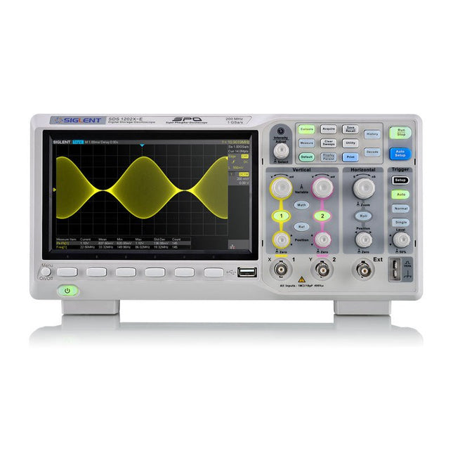
Siglent Siglent SDS1202X-E 2-ch Oscilloscope (200 MHz)
SIGLENT’s SDS1000X-E Series Super Phosphor Oscilloscope is available in one bandwidth, 200 MHz. It has a maximum sample rate of 1 GSa/s and a standard record length of 1 Mpts. For ease-of-use, the most commonly used functions can be accessed with its user-friendly front panel design. The SDS1000X-E series employs a new generation of SPO (Super Phosphor Oscilloscope) technology that provides excellent signal fidelity and performance. The system noise is also lower than similar products in the industry. It comes with a minimum vertical input range of 500 uV/div, an innovative digital trigger system with high sensitivity and low jitter, and a waveform capture rate of 400,000 frames/ sec (sequence mode). The SDS1000X-E also employs a 256-level intensity grading display function and a color temperature display mode not found in other models in this class. Siglent’s latest oscilloscopes offering supportsmultiple powerful triggering modes including serial bus triggering. Decoding is standard configuration including IIC,SPI,UART,CAN,LIN. History waveform recording and sequential triggering enable extended waveform recording and analysis. Another powerful addition is the new 1 million points FFT math function that gives the SDS1000X-E very high frequency resolution when observing signal spectra. The new design also includes a hardware co-processor that delivers measurements quickly and accurately. The features and performance of Siglent’s new SDS1000X-E cannot be matched anywhere else in this price class. Specifications Bandwidth 200 MHz Channels 2CH+1EXT Real time sampling rate 1 GSa/s Memory depth 7 Mpts/CH (Dual-Channel); 14 Mpts/CH (Single-Channel) Waveform Capture Rate (Max.) 100,000 wfm/s (normal mode); 400,000 wfm/s (sequence mode) Serial Trigger (Standard) I²C, SPI, UART/RS232, CAN, LIN Decode Type (Standard) I²C, SPI, UART/RS232, CAN, LIN Trigger Type Edge, Slope, Pulse Width, Window, Runt, Interval, Dropout, Pattern, Video Probe (Std) 2 pcs passive probe PP215 Display 7 inch TFT-LCD (800x480) Weight Without package 2.5 kg; with package 3.5 kg Downloads Datasheet Manual Programming Guide
€ 401,99
-
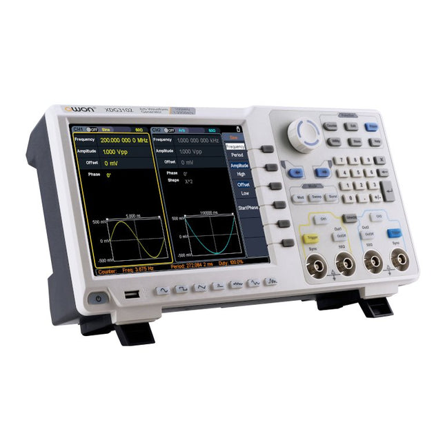
OWON OWON XDG3102 2-ch Arbitrary Waveform Generator (100 MHz)
Features Advanced DDS technology, up to 250 MHz frequency output 1.25 GS/s sampling rate, and 1 μHz frequency resolution Up to 1M arbitrary waveform length Vertical resolution: 14 bits Comprehensive waveform output: 6 groups waveforms, and 152 group built-in arbitrary waveforms Comprehensive modulation options: AM, FM, PM, FSK, 3FSK, 4FSK, PSK, OSK, ASK, BPSK, PWM, sweep, and burst High-accuracy frequency counter integrated, ranging from 100MHz till 200MHz SCPI and LabVIEW supported 8-inch 800 x 600 pixels touch screen LCD Specifications XDG3102 Channel 2 Frequency Output 100MHz Sample Rate 1.25GSa/s Vertical Resolution 14 bits Waveform Standard Waveform sine, square, pulse, ramp, noise, and harmonic Arbitrary Waveform exponential rise, exponential fall, sin(x)/x, step wave, and others, total of 150 built-in waveforms, and user-defined arbitrary waveform Frequency (resolution 1μHz) Sine 1μHz - 100MHz Square 1μHz - 40MHz Pulse 1μHz - 25MHz Ramp 1μHz - 5MHz Harmonic 1μHz - 50MHz Noise 120MHz (-3dB, typical) Arbitrary Waveform built-in waveform: 1uHz - 15MHzuser-defined waveform: 1uHz - 50MHz Accuracy ±1ppm, 0°C - 40°C Amplitude Amplitude (50Ω) 1mVpp - 10Vpp (≤40MHz); 1mVpp - 5Vpp (≤80MHz) 1mVpp - 2.5Vpp (≤120MHz); 1mVpp - 1Vpp (≤250MHz) Amplitude(high impedance) 2mVpp - 20Vpp (≤40MHz); 2mVpp - 10Vpp (≤80MHz); 2mVpp - 5Vpp (≤120MHz); 2mVpp - 2Vpp (≤250MHz) Resolution 1mV or 4 digits DC Offset Range (50Ω) ±(5 Vpk - Amplitude Vpp/2) Range (high-Z, open circuit) ±(10 Vpk - Amplitude Vpp/2) Accuracy ±(1% of |setting| + 1mV + Amplitude Vpp x 0.5%) Resolution 1mV or 4 digits Load Impedance 50Ω (typical) Accuracy ±(1% of setting + 1 mVpp) (typical, 1kHz sine, 0V offset) Sine Wave Spectrum Purity Harmonic Distortion Typical (0dB) DC - 1MHz: <-65dBc 1MHz - 10MHz: <-60dBc 10MHz - 120MHz: <-50dBc 120MHz - 200MHz: <-45dBc Total Harmonic Distortion <0.05 %, 10 Hz to 20 kHz, 1 Vpp Spurious (non-harmonic), Typical (0dB) ≤10MHz: <-70dBc >10MHz: <-70dBc + 6dB/ octave Phase Noise Typical (0 dBm, 10 kHz deviation) 10MHz: ≤-110dBc/Hz Square Rise/Fall Time <5ns Overshoot <3% Duty Cycle 50.0% (fixed) Jitter (rms) 300ps + 100ppm Pulse Pulse Width 12ns - 996875s Leading/Trailing Edge Time ≧7ns Overshoot <3% Jitter (rms) 300ps + 100ppm Ramp Linearity ≤1% of peak output (typical, 1kHz, 1 Vpp, 50% symmetry) Symmetry 0% to 100% Harmonic Harmonic Order ≤16 Harmonic Type even, odd, all, user Harmonic Amplitude could be set for all the harmonics Harmonic Phase Arbitrary Waveform Length 2 points - 1M points Vertical Resolution 14 bits Minimum Rise/Fall Time <7ns Jitter (rms) 3ns Modulation Type AM, FM, PM, PWM, FSK, 3FSK, 4FSK, PSK, OSK, ASK, BPSK, sweep, and burst AM Carrier Waveform sine, square, ramp, and arbitrary (except DC) Source internal / external Modulating Waveform sine, square, ramp, noise, and arbitrary Depth 0.0% - 100.0% Modulating Frequency 2 mHz - 100 kHz FM Carrier Waveform sine, square, ramp, and arbitrary (except DC) Source internal / external Modulating Waveform sine, square, ramp, noise, and arbitrary Modulating Frequency 2 mHz - 100 kHz PM Carrier Waveform sine, square, ramp, and arbitrary (except DC) Source internal / external Modulating Waveform sine, square, ramp, noise, and arbitrary Phase Deviation 0° - 180° Modulating Frequency 2 mHz - 100 kHz PWM Carrier Waveform pulse Source internal / external Modulating Waveform sine, square, ramp, noise, and arbitrary Width Deviation 0 ~ minimum (pulse duty ratio, 100% - pulse duty ratio) Modulating Frequency 2 mHz - 100 kHz FSK / 3FSK / 4FSK Carrier Waveform sine, square, ramp, and arbitrary (except DC) Source internal / external Modulating Waveform square with 50% duty cycle Key Frequency 2 mHz - 1MHz PSK Carrier Waveform sine, square, ramp, and arbitrary (except DC) Source internal / external Modulating Waveform square with 50% duty cycle Key Frequency 2 mHz - 1MHz OSK Carrier Waveform sine, square, ramp, and arbitrary (except DC) Source internal Oscillation Time square with 50% duty cycle Key Frequency 2 mHz - 1MHz ASK Carrier Waveform sine, square, ramp, and arbitrary (except DC) Source internal / external Modulating Waveform square with 50% duty cycle Key Frequency 2 mHz - 1MHz BPSK Carrier Waveform sine, square, ramp, and arbitrary (except DC) Source internal Modulating Waveform square with 50% duty cycle Key Frequency 2 mHz - 1MHz Sweep Carrier Waveform sine, square, ramp, and arbitrary (except DC) Type linear, and log Direction up, and down Sweep Time 1 ms to 500s, ± 0.1% Trigger Source internal, external, and manual Burst Carrier Waveform sine, square, ramp, pulse, and arbitrary (except DC) Burst Count 1 to 50,000 period, infinite, gating Internal Period 10 ns - 500 s Gated Source external trigger Frequency Counter Function frequency period, +width, -width, +duty, and -duty Frequency Range 100 MHz - 200 MHz Frequency Resolution 7 digits Input / Output Display 8”800 x 600 pixels touch screen LCD Type frequency counter, external modulation input,external trigger input,external reference clock input / output Communication Interface USB Host, USB Device, and LAN Dimension 340 x 177 x 90 mm Weight 2.50 kg
€ 650,00


