
Search results for "fahrzeugdiagnose OR mit OR obd OR 2"
-

Elektor Digital Elektor 11-12/2021 (PDF)
NVIDIA JETSON NANO - BILDVERARBEITUNG FÜR EINSTEIGER (TEIL 2)Erkennen von Objekten mit Edge Impulse ELEKTOR JUMPSTARTER-NEWSKommende Kampagnen OPEN-SOURCE-GPS-TRACKING-PLATTFORMFahrzeug-Tracking ohne fremde Cloud mit Traccar MULTIFUNKTIONS-KOMPONENTENTESTER LCR-T7 VON JOY-ITTesten von passiven Bauteilen, diskreten Halbleitern und IR-Fernbedienungen RAUSCH-SYNTHESIZERVom Rauschen zur Musik mit dem PRBSynth1 ALLER ANFANG …ist gar nicht schwer! Weiter geht's mit der Spule... DIE NEURONEN IN NEURONALEN NETZEN VERSTEHENTeil 2: Logische Neuronen BLITZLICHT-GESCHÜTZTER ANALOGSPEICHER-ZUSATZ FÜR DAS MANIPULATIONSSICHERE DATENPAKETProbleme mit der Sicherheit? Bekämpfen Sie Feuer mit Feuer! LCR METER POSTER BLUETOOTH-BEACONS IN DER PRAXISOrtsbestimmung in Innenräumen C-PROGRAMMIERUNG AUF RASPBERRY PIEin Beispielkapitel: Kommunizieren über WLAN EMV-VORKONFORMITÄTSTEST FÜR IHR DC-VERSORGTES PROJEKTTeil 2: Die Hardware und wie man sie benutzt PARALLAX PROPELLER 2Teil 5: Das Innenleben des Smart Pins MODBUS ÜBER WLANTeil 1: Hardware und Programmierung ZUTRITT FÜR UNBEFUGTE VERBOTENWie der Junior-Computer wieder zum Leben erweckt wurde BAUEN SIE IHREN EIGENEN HOCHPRÄZISIONSKALIBRATOR-10 V bis +10 V, 0 bis 40 mA, 0,001% ARDUINO NANO RP2040 CONNECTRaspberry Pi RP2040 + WLAN + Bluetooth DER PHYSISCHE KÖRPER DER KÜNSTLICHEN INTELLIGENZ PROJEKT 2.0Korrekturen, Updates und Leserbriefe GRAFISCHE BENUTZEROBERFLÄCHEN MIT PYTHON UND GUIZERO CO2-MESSGERÄT-SET FÜRS KLASSENZIMMEREin ESP8266-basiertes Gerät, entwickelt von der FH Aachen NOSTALGISCHES MW/LW-RADIO MIT MK484...macht immer Spaß zu bauen! 60 JAHRE ELEKTOREs werde Licht! HEXADOKUThe Original Elektorized Sudoku
€ 11,90
-
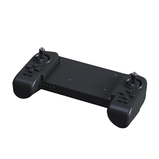
Unitree Unitree Go2 Remote Controller
The Unitree Go2 Controller is a dedicated remote control device designed for seamless and precise operation of the Unitree Go2 Quadruped Robot. This bimanual remote features built-in data transmission and Bluetooth modules, facilitating reliable wireless communication with the robot. It offers an ultra-long control distance of over 100 meters in open environments, ensuring flexibility in various operational scenarios. Specifications Charging Voltage 5 V Charging Current 2 A Frequency 2.4 GHz Communication Modes Data transmission module and Bluetooth Battery Capacity 2500 mAh Operating Time approx. 4.5 hours Control Distance Over 100 meters in open environments
€ 299,00
Best Price
-

Elektor Digital Elektor 03-04/2022 (PDF)
Mein eigener RISC-V-ControllerErste Schritte mit dem NEORV32 RISC-V Softcore für preiswerte FPGAs Wie man den Seriellen Plotter der Arduino-IDE nutztEinfaches Plotten von Kurven mit Arduino CLUE - ein Clou von Adafruit?Angriff auf den micro:bit Puffer-Board für den Raspberry Pi 400Schützen Sie die I/Os! FrühjahrskollektionInteressante Raspberry Pi RP2040 Boards Ein DIY-Handbuch zu elektronischer Sicherheit und E-SpionageSRAM erhitzt oder tiefgefroren Identifizierung von BauteilenTipps & Tricks, Best Practices und andere nützliche Informationen Ein Touch-Schalter ohne TouchKonzeption und Umsetzung eines berührungslosen Lichtschalters Aller Anfang...ist gar nicht schwer: Anpassen und Transformieren Was gibt's Neues in der Embedded-Entwicklung?Rust und die Aktualisierung von IoT-Implementierungen Infografiken Elektor Industry Neue Wege für Industrie und Automobilbranche mit 5G DrehspulrelaisBemerkenswerte Bauteile Zutritt für Unbefugte verbotenAlles dreht sich um die Werkzeuge... Die Neuronen in neuronalen Netzen verstehenTeil 4: Eingebettete Neuronen Magnetische Levitation auf die sehr sehr einfache ArtDie dritte und kompakteste Version SPS-Programmierung mit dem Raspberry Pi und dem OpenPLC-ProjektVisualisierung von SPS-Programmen mit AdvancedHMI Aus dem Leben gegriffenEinpacken und weg damit Unter dem RadarUnbekannte Mikrocontroller, über die Sie Bescheid wissen sollten Drahtloses Monitoring und DebuggenSerielle Funk-Schnittstelle für Arduino, ESP32 und Co. Tragbares Temperatur- und FeuchtemessgerätGebaut mit vorgefertigten Modulen Lithium-Akkus reparierenGeld sparen + mehr Power! GUIs mit PythonMeme-Generator Die drei FragezeichenWarum? Was? Wer? Hexadoku
€ 11,90
-
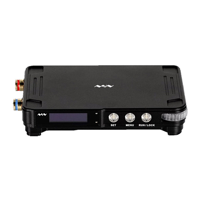
Miniware Miniware MDP-P906 Digital Power Supply (300 W)
MDP-P906 has a built-in cooling fan, and maximum output power of up to 300 W, which meets a wider range of testing needs and application scenarios. Through 2.4 GHz wireless communication, it can be connected to MDP-M01 Smart Digital Monitor module to realize the free combination of multiple channels of 300 W per channel. MDP-P906 has the index, stability and reliability comparable to a professional power supply. It can output pure current, and provide powerful functions such as programmable output, timing output, timing control, automatic compensation, boost mode, etc., making itself a real cost-effective, smart and customized programmable linear DC power supply. MDP-P906 adopts a precision CNC machined aluminum alloy shell, with fine workmanship, novel, mini and beautiful appearance, it completely subverts the rigid image of traditional desktop power supply. With stackable modular design and wireless communication function, MDP-P906 can work independently or paired, both on the workbench, and be carried out for on-site maintenance. MDP-P906 is a perfect solution for electronic engineer, especially field application engineers to meet different needs of power sources. Built-in silent cooling fan, instant cooling, ensure a stable and efficient output! Smart linear compensation, constant voltage & constant current Positive & negative output, series boost, parallel current sharing Applications Universal tests and teaching experiments in R&D laboratory Maintenance of digital products Property verification and fault diagnosis of devices and circuits Emergency power supply for model airplanes and vehicles Power supply testing of RF and microwave circuits or modules Quality control and quality inspection Supply purified power for high-accuracy digital-analog hybrid circuits and Hi-Fi audio devices Specifications Input DC 4.2-30 V/14 A (Max)QC 3.0/PD2.0, 20 V/5 A (Max) Output 0-30 V/0-10 A, 300 W (Max) Conversion efficiency 95% Output resolution 10 mV/2 mA, up to 1 mV/1 mA via Display Control module Output accuracy 0.03%+5 mV0.05%+2 mV Adjustment rate Load adjustment rate <±0.01%Power adjustment rate <±0.01% Ripple and noise <250 uVrms, 3 mVpp; 2 mArms Transient response <4 uS Safety protections Input over-voltage, under-voltage, reverse connection protection, output over-current, back-flow protection and over-temperature protection Others Automatically shut-down and enter micro-power modeSupport USB firmware upgrade Dimensions 112 x 66 x 20 mm Weight 181 g Included 1x MDP-P906 Digital Power Supply 2x Output Cable 1x User Manual Downloads User Manual v1.1 Firmware v1.32
€ 171,95
-

Unitree Unitree G1 Humanoid Robot
The Unitree G1 is a modern humanoid robot that impresses with its remarkable flexibility and advanced technology. With an exceptionally wide range of joint movement and up to 43 joint motors, it exceeds the agility of a typical human. Powered by imitation learning and reinforcement learning, its robotic systems are continuously developed and optimized through artificial intelligence. One of the G1's most impressive features is its ability to autonomously move into a walking position as soon as it touches the ground – no external assistance required! It can immediately start moving, demonstrating a high level of independence and adaptability. The G1 is also equipped with a force-controlled, highly dexterous hand that operates with both sensitivity and precision, thanks to its combination of force and position control. This hand closely mimics human movements, allowing for precise object manipulation. Features Intel RealSense D435 Depth Camera Livox MID-360 3D LiDAR Microphone array (noise and echo cancellation) 5 W stereo speaker Extra large quick release battery Single arm degrees of freedom (shoulder 2 + elbow 2) Hollow joint wiring of the whole machine (no external cables) Maximum torque at joints 120 N.m Single leg degrees of freedom (hip 3, knee 1, ankle 2) Moving speed of 2 m/s Specifications Height, Width and Thickness (Stand) 1320 x 450 x 200 mm Height, Width and Thickness (Fold) 690 x 450 x 300 mm Weight (with Battery) approx. 35 kg Total Degrees of Freedom(Joint Freedom 23 Single Leg Degrees of Freedom 6 Waist Degrees of Freedom 1 Single Arm Degrees of Freedom 5 Joint output bearing Industrial grade crossed roller bearings (high precision, high load capacity) Joint motor Low inertia high-speed internal rotor PMSM (Permanent Magnet Synchronous Motor – better response speed and heat dissipation) Maximum Torque of Knee Joint 90 N.m Arm Maximum Load approx. 2 kg Calf + Thigh Length 0.6 m Arm Span approx. 0.45 m Extra Large Joint Movement Space • Waist joint: Z ±155°• Knee joint: 0~165°• Hip joint: P ±154°, R -30~+170°, Y ±158° Full Joint Hollow Electrical Routing Yes Joint Encoder Dual encoder Cooling System Local air cooling Power Supply 13 string Lithium battery Basic Computing Power 8-core high-performance CPU Sensing Sensor Depth Camera + 3D LiDAR Microphones 4 Microphone Array Speaker 5 W stereo speaker Wireless WiFi 6, Bluetooth 5.2 Smart Battery (Quick Release) 9000 mAh Charger 54 V/5 A Manual Controller Yes Battery Life approx. 2 hours Upgraded Intelligent OTA Yes
€ 24.999,00
Best Price
-
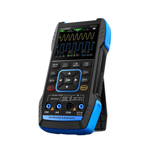
FNIRSI FNIRSI 2C53T (3-in-1) 2-ch Oscilloscope (50 MHz) + Multimeter + Signal Generator
The FNIRSI 2C53T, an enhanced version of its 10 MHz predecessor, is a compact and versatile 3-in-1 device. It combines a dual-channel 50 MHz oscilloscope, a 4.5-digit True RMS multimeter, and a signal generator with 13 waveform types, making it an essential tool for maintenance and research professionals. Oscilloscope: Features 50 MHz bandwidth, 250 MS/s sampling rate, ±400 V protection, FPGA + ARM + ADC architecture, and waveform saving for analysis. Multimeter: 4.5-digit True RMS with 19999 counts, supports AC/DC voltage, current, capacitance, resistance, diode, and continuity measurements. Signal Generator: Outputs 13 signal types up to 50 KHz, with adjustable frequency, amplitude, and duty cycle. With a 2.8-inch LCD, 3000 mAh battery (6-hour runtime), and a portable design, it delivers powerful functionality in a user-friendly package. Specifications Oscilloscope Channels 2 Analog Bandwidth 50 MHz Real-time Sampling Rate 250 MS/s Storage Depth 1 Kpts Impedance 1 MΩ Time Base Range 10ns-20s Vertical Sensitivity 10 mV/div-10 V/div (x1) Maximum Measured Voltage ±400 V Trigger Mode Auto/Normal/Single Trigger Type Rising edge, Falling edge Display Mode Y-T/Rolling/X-Y Coupling Method AC/DC Persistence OFF, 500ms, 1s, ∞ Math 8 Basic Operations + FFT Supported Waveform Screenshot Save, Export Waveform Image, Cursor Measurement, Infinite Afterglow Multimeter DC Voltage 1.9999V/19.999V/199.99V/1000V ±(0.5%+3) AC Voltage 1.9999V/19.999V/199.99V/750.0V ±(1%+3) DC Current 19.999mA/199.99mA/1.9999A/9.999A ±(1.2%+3) AC Current 19.999mA/199.99mA/1.9999A/9.999A ±(1.5%+3) Resistance 19.999MΩ/1.9999MΩ/199.99KΩ/19.999KΩ ±(0.5%+3) 1.9999KΩ/199.99Ω ±(2.0%+3) Capacitance 999.9uF/99.99uF/9.999uF/999.9nF/99.99nF/9.999nF ±(2.0%+5) 9.999mF/99.99mF ±(5.0%+20) Temperature −55~1300°C (−67~2372°F) ±(2.5%+5) Continuity Test Yes Diode Yes Signal Generator 13 Signal Waveforms Sine wave, rectangular wave, sawtooth wave, half wave, full wave, positive step wave, reverse step wave, exponential rise, exponential fall, DC, multi-audio, Sinker pulse, Lorentz wave Output Frequency 0-50 KHz Output Amplitude 0-3 V Output Duty Cycle 0-100% General Display 2.8" HD color screen Resolution 320 x 240 Charging USB-C (5 V/1 A) Battery 3000 mAh Lithium battery Standby Time 6 hours Languages English, Chinese Dimensions 167 x 89 x 35 mm Weight 300 g Differences New vs Old Version Model 2C53T Upgrade 2C53T Predecessor Bandwidth 50 MHz 10 MHz Display Mode Y-T/Rolling/X-Y Y-T/Rolling Math 8 Basic Operations + FFT N/A Cursor Function Yes N/A XY Lissau Graph Yes N/A Afterglow Function Yes N/A Multimeter Accuracy 19999 Counts 9999 Counts Signal Generator 50 KHz 2 MHz Included 1x FNIRSI 2C53T Oscilloscope (50 MHz) 2x P6100 Oscilloscope probes (10X) 1x Multimeter probe 1x Alligator clip probe 1x USB-C charging cable 1x Storage bag 1x Manual Downloads Manual Firmware V1.2.0
-

Elektor Bundles Mikrocontroller-Praxiskurs für Arduino-Einsteiger (Bundle)
Mit dem Elektor Arduino Nano Trainingsboard (MCCAB) eigene Projekte realisieren Der Mikrocontroller ist das wohl faszinierendste Teilgebiet der Elektronik, denn aufgrund der Vielzahl von Funktionen, die er auf seinem Chip vereinigt, ist er für den Entwickler ein universelles Multi-Tool zur Realisierung seiner Projekte. Praktisch jedes Gerät des täglichen Gebrauchs wird heute von einem Mikrocontroller gesteuert. Für einen elektronischen Laien blieb es aufgrund der Komplexität bisher allerdings ein Wunschtraum, eigene Ideen mit einem Mikrocontroller zu realisieren. Das Arduino-Konzept hat den Einsatz von Mikrocontrollern weitgehend vereinfacht, sodass jetzt auch Laien eigene Elektronik-Ideen mit einem Mikrocontroller verwirklichen können. Buch & Hardware im Bundle: 'Learning by Doing' Dieses im Bundle mitgelieferte Buch (im großen A4-Format) zeigt, wie man auch ohne große Erfahrung in Elektronik und Programmiersprachen eigene Projekte mit einem Mikrocontroller realisieren kann. Es ist ein Mikrocontroller-Praxiskurs für Einsteiger, denn nach einem Überblick über die Interna des Mikrocontrollers und einer Einführung in die Programmiersprache C liegt der Schwerpunkt des Kurses auf den praktischen Übungen. Der Leser eignet sich die erforderlichen Kenntnisse durch 'Learning by Doing' an: in dem umfangreichen Praxisteil mit 12 Projekten und 46 Übungen wird das im vorderen Teil des Buches Gelernte mit vielen Beispielen unterlegt. Die Übungen sind dabei so aufgebaut, dass der Bearbeiter eine Aufgabenstellung erhält, die er mit seinem im Theorieteil des Buches aufgebauten Wissen löst. Für jede Übung gibt es anschließend eine ausführlich erklärte und kommentierte Musterlösung, die dem Bearbeiter bei Problemen weiterhilft und die er mit seiner eigenen Lösung vergleichen kann. Arduino IDE In der Arduino IDE, einer Software-Entwicklungsumgebung, die kostenlos auf den eigenen PC heruntergeladen werden kann und die das gesamte Softwarepaket enthält, das für ein eigenes Mikrocontroller-Projekt benötigt wird, schreibt der Bearbeiter mit dem Editor der IDE seine Programme („Apps“) in der Programmiersprache C. Der in die Arduino IDE integrierte Compiler übersetzt sie in die Bits und Bytes, die der Mikrocontroller versteht und die dann über ein USB-Kabel in den Speicher des Mikrocontrollers auf dem Elektor Arduino Nano Trainingsboard (MCCAB) geladen werden. Externe Sensoren, Motoren oder Baugruppen abfragen oder steuern Das Elektor Arduino Nano Trainingsboard (MCCAB) enthält neben einem Mikrocontrollermodul Arduino Nano alle für die Übungen benötigten Bauteile wie Leuchtdioden, Schalter, Taster, akustische Signalgeber usw. Auch externe Sensoren, Motoren oder Baugruppen können mit diesem Mikrocontroller-Übungssystem abgefragt oder gesteuert werden. Technische Daten (Arduino Nano Trainingsboard MCCAB) Stromversorgung Über die USB-Verbindung des zur Erstellung der Programme sowieso angeschlossenen PCs oder ein externes Netzteil (nicht im Lieferumfang enthalten) Betriebsspannung +5 Vcc Eingangsspannung Alle Eingänge 0 V bis +5 V VX1 und VX2 +8 V bis +12 V (nur bei Verwendung eines externen Netzteils) Mikrocontrollermodul Arduino Nano Hardwareperipherie LCD 2x16 Zeichen Potenziometer P1 & P2 JP3: Auswahl der Betriebsspannung von P1 & P2 Verteiler SV4: Verteiler für die BetriebsspannungenSV5, SV6: Verteiler für die Ein-/Ausgänge des Mikrocontrollers Schalter und Taster RESET-Taster auf dem Arduino Nano-Modul6x Tastschalter K1 … K66x Schiebeschalter S1 … S6JP2: Verbindung der Schalter mit den Eingängen des Mikrocontrollers Summer Piezo-Summer Buzzer1 mit Steckbrücke auf JP6 Leuchtanzeigen LED L auf dem Arduino Nano-Modul, verbunden mit GPIO D1311x LED: Zustandsanzeige für die Ein-/AusgängeJP6: Verbindung der LEDs LD10 … LD20 mit den GPIOs D2 … D12 Serielle SchnittstellenSPI & I²C JP4: Auswahl des Signals an Pin X der SPI-Steckerleiste SV12SV9 bis SV12: SPI-Interface (3,3 V/5 V) bzw. I²C-Interface Schaltausgang für externe Geräte SV1, SV7: Schaltausgang (maximal +24 V/160 mA, extern zugeführt)SV2: 2x13 Pins zum Anschluss externer Module 3x3 LED-Matrix (9 rote LEDs) SV3: Spalten der 3x3 LED-Matrix (Ausgänge D6 … D8)JP1: Verbindung der Reihen mit den GPIOs D3 … D5 Software Library MCCABLib Steuerung der Hardware-Komponenten (Schalter, Taster, Leuchtdioden, 3x3 LED-Matrix, Summer) auf dem MCCAB Trainingsboard Betriebstemperatur bis +40 °C Abmessungen 100 x 100 x 20 mm Technische Daten (Arduino Nano) Mikrocontroller ATmega328P Architektur AVR Betriebsspannung 5 V Flashspeicher 32 KB, davon 2 KB vom Bootloader belegt SRAM 2 KB Taktfrequenz 16 MHz Analoge IN-Pins 8 EEPROM 1 KB DC-Strom pro I/O-Pin 40 mA an einem I/O-Pin, insgesamt maximal 200 mA an allen Pins gemeinsam Eingangsspannung 7-12 V Digitale I/O-Pins 22 (6 davon sind PWM-fähig) PWM-Ausgänge 6 Stromverbrauch 19 mA Abmessungen 18 x 45 mm Gewicht 7 g Lieferumfang Elektor Arduino Nano MCCAB Trainingsboard Arduino Nano Buch: Mikrocontroller-Praxiskurs für Arduino-Einsteiger
-

Elektor Publishing KiCad Like A Pro – Advanced Projects and Recipes
Mastering PCB design with real-world projects This book builts on KiCad Like a Pro – Fundamentals and Projects and aims to help you practice your new KiCad skills by challenging you in a series of real-world projects. The projects are supported by a comprehensive set of recipes with detailed instructions on how to achieve a variety of simple and complex tasks. Design the PCBs for a solar power supply, an LED matrix array, an Arduino-powered datalogger, and a custom ESP32 board. Understand the finer details of the interactive router, how to manage KiCad project teams with Git, how to use an autorouter on 2 and 4-layer PCBs, and much more. KiCad 8 is a modern, cross-platform application suite built around schematic and design editors. This stable and mature PCB tool is a perfect fit for electronic engineers and makers. With KiCad 8, you can create PCBs of any complexity and size without the constraints associated with the commercial packages. Here are the most significant improvements and features in KiCad 8, both over and under the hood: Modern user interface, completely redesigned from earlier versions Improved and customizable electrical and design rule checkers Theme editor allowing you to fully customize the look of KiCad on your screen Ability to import projects from Eagle, CADSTART, and more An improved and tightly integrated SPICE circuit simulator Autorouting with the Freerouting plugin Filters define which elements of a layout are selectable Enhanced interactive router helps you draw single tracks and differential pairs with precision New or enhanced tools to draw tracks, measure distances, tune track lengths, etc. Enhanced tool for creating filled zones A customizable coordinate system facilitates data exchange with other CAD applications Realistic ray-tracing capable 3D viewer Differential pair routing Rich repositories of symbol, footprint, and 3D shape libraries Python scripting API for programmatic customization and extensions Improved footprint wizard for fast custom footprints
-

NXP Semiconductors NXP FRDM-MCXN947 Development Board
The FRDM-MCXN947 is a compact and versatile development board designed for rapid prototyping with MCX N94 and N54 microcontrollers. It features industry-standard headers for easy access to the MCU's I/Os, integrated open-standard serial interfaces, external flash memory, and an onboard MCU-Link debugger. Specifications Microcontroller MCX-N947 Dual Arm Cortex-M33 cores @ 150 MHz each with optimized performance efficiency, up to 2 MB dual-bank flash with optional full ECC RAM, External flash Accelerators: Neural Processing Unit, PowerQuad, Smart DMA, etc. Memory Expansion *DNP Micro SD card socket Connectivity Ethernet Phy and connector HS USB-C connectors SPI/I²C/UART connector (PMOD/mikroBUS, DNP) WiFi connector (PMOD/mikroBUS, DNP) CAN-FD transceiver Debug On-board MCU-Link debugger with CMSIS-DAP JTAG/SWD connector Sensor P3T1755 I³C/I²C Temp Sensor, Touch Pad Expansion Options Arduino Header (with FRDM expansion rows) FRDM Header FlexIO/LCD Header SmartDMA/Camera Header Pmod *DNP mikroBUS User Interface RGB user LED, plus Reset, ISP, Wakeup buttons Included 1x FRDM-MCXN947 Development Board 1x USB-C Cable 1x Quick Start Guide Downloads Datasheet Block diagram


