The FNIRSI TMP-610S is a compact 3-in-1 test instrument combining a True RMS multimeter, 10 MHz oscilloscope, and 50 kHz DDS signal generator. It is designed for electronics troubleshooting, circuit testing, and development in the lab or on the go.
The multimeter offers 60,000-count resolution and supports voltage, current, resistance, capacitance, frequency, temperature, diode, and continuity measurements. The integrated oscilloscope provides real-time waveform analysis at up to 48 MSa/s, while the signal generator supports 13 waveform types with adjustable frequency, amplitude, and duty cycle.
A 3.5-inch IPS touchscreen, smart auto-scan, Bluetooth connectivity for DMM functions, waveform storage, USB export, and a 3,000 mAh rechargeable battery make the TMP-610S a versatile all-in-one tool for electronics professionals and enthusiasts.
Features
3-in-1 Design: DMM + Oscilloscope + Signal Generator
60,000-Count True RMS High-Precision Measurement
10 MHz Oscilloscope with 48 MSa/s Sampling Rate
Bluetooth App Sync (Multimeter Function Only)
3.5-inch Smart Touchscreen with Multiple Display Modes
50 kHz DDS Signal Generator with 13 Waveforms
Built-in Fuse for Easy Replacement
Specifications
Multimeter
Function
Range
Accuracy
DC voltage
600mV/6V/60V/600V/1000V
±(0.03%+5d)
AC voltage
600mV/6V/60V /600V/750V
±(0.3%+15d)
DC current
600uA/6000uA/60mA/600mA
±(0.15%+5d)
6A/10A
±(0.2%+5d)
AC current
600uA/6000uA/60mA/600mA
±(0.5%+15d)
6A/10A
±(0.75%+15d)
Resistance
600Ω/6KΩ/60KΩ/600KΩ/6MΩ
±(0.1%+5d)
60MΩ
±(0.2%+10d)
Capacitance
60nF/600nF/6uF/60uF
±(2.5%+30d)
600uF/6mF/60mF
±(3.5%+30d
Frequency
10 Hz~60 MHz
±(0.01%+5d)
Temperature
-40℃~1000℃
±(1.0%+5℃)
Continuity
0Ω~1KΩ
±(0.2%+5d)
Diode
0V~3.0V, 0Ω~1 Ω
±(1%+5d)
AC frequency response
10KHz
/
Oscilloscope
Real-time Sampling Rate
48 MSa/s
Analog Bandwidth
10 MHz
Input Impedance
1MΩ
Coupling Mode
AC/DC
Test Voltage Range
1:1 Probe - 80Vpp (±40V)
10:1 Probe - 800Vpp (±400V)
Vertical Sensitivity
10mV/div~10V/div
Vertical Displacement
Adjustable with indication
Horizontal Time Base Range
50 ns ~ 20 s
Trigger Mode
Auto, Normal, Single
Trigger Type
Rising, Falling, 50%
Trigger Level
Adjustable with indication
Measurement Parameters
Freq, Period, +Duty, ‒Duty, +Width, ‒Width, Max, Min, P‒P, Amp, RMS, Avg
Persistence
Off / 500ms / 1s / ∞
Cursor Measurement
Yes
Waveform Screenshot Saving
Yes
Signal Generator
Output Waveform
Supports 13 waveform types
Frequency
0~50kHz
Amplitude
0.0V~3.0V
Duty Cycle
0~100%, adjustable for Square and Sawtooth waves
Included
1x FNIRSI TMP-610S Multimeter + Oscilloscope + Signal Generator
1x P6100 Probe
1x Adapter
2x Alligator Clips
2x Multimeter Probes
Probe Accessories
1x Storage Bag
1x USB-C Cable
1x Manual
Downloads
Manual
The FNIRSI SWM-20 handheld spot welder is a high-efficiency, user-friendly, and easy-to-carry welding tool. It features dual-pulse spot welding technology, ensuring more stable and reliable welds, and also includes a convenient power bank function.
Equipped with a 2.4-inch HD display, the SWM-20 offers clear and intuitive operation. Its rotary encoder knob allows users to adjust parameters quickly and precisely, making it easy to set the required welding settings and improving the overall user experience.
Features
2-in-1: Spot Welder & 5000 mAh Power Bank
1200 A High-Power Output for Strong, Reliable Welds
Dual-Pulse Technology for Cleaner & More Stable Welding
Dual A-Grade Batteries with 8 Safety Protections
0.1–0.5 mm Multi-Material Welding Capability
10,000+ Precision Adjustment Levels for Professional Control
2.4-inch TFT Display with Real-Time Data Monitoring
Specifications
Max Welding Current
1200 A
Battery Capacity
5000 mAh
Charging
5 V/2.1 A
Discharging
5 V/2.1 A
Welding Materials
Nickel, Iron, Stainless Steel
Welding Thickness
0.1‒0.5 mm
Level
4 Preset Combination Levels
Dimensions
13.3 x 8.8 x 3.2 cm
Weight
850 g
Included
1x FNIRSI SWM-20 Spot Welder
2x Welding Pens
2x Replacement Tips
1x Nickel Strip
1x USB-C Cable
1x Manual
Downloads
Manual
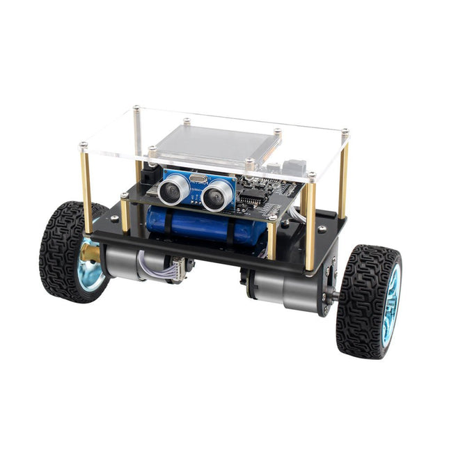
Arduino-compatible, ESP32-controlled, 2-wheeled Balancing Robot
The Elektor Mini-Wheelie is an experimental autonomous self-balancing robot platform. Based on an ESP32-S3 microcontroller, the self-balancing robot is fully programmable using the Arduino environment and open-source libraries. Its wireless capabilities allow it to be controlled remotely over Wi-Fi, Bluetooth or ESP-NOW or to communicate with a user or even another robot.
An ultrasonic transducer is available for detecting obstacles. Its color display can be used for displaying cute facial expressions or, for the more down-to-earth users, cryptic debug messages.
The robot comes as a neat kit of parts that you must assemble yourself. Everything is included, even a screwdriver.
Note: The Mini-Wheelie is an educational development platform intended for learning, experimentation, and robotics development. It is not classified as a toy for children, and its features, documentation, and intended audience reflect this purpose. The product is aimed at students, educators, and developers who wish to explore robotics, programming, and hardware integration in an educational setting.
Specifications
ESP32-S3 microcontroller with Wi-Fi and Bluetooth
MPU6050 6-axis Inertial Measurement Unit (IMU)
Two independently controlled 12 V electric motors with tachometer
Ultrasonic transducer
2.9" TFT color display (320 x 240)
MicroSD card slot
Battery power monitor
3S rechargeable Li-Po battery (11.1 V/2200 mAh)
Battery charger included
Arduino-based open-source software
Dimensions (W x L x H): 23 x 8 x 13 cm
Included
1x ESP32-S3 Mainboard + MPU6050 module
1x LCD board (2.9 inch)
1x Ultrasonic sensor
1x Battery pack (2200 mAh)
1x Battery charger
1x Motor tyre kit
1x Case board
1x Acrylic board
1x Screwdriver
1x Protective strip
1x Flex cable B (8 cm)
1x Flex cable A (12 cm)
1x Flex cable C
4x Copper column A (25 mm)
4x Copper column B (55 mm)
4x Copper column C (5 mm)
2x Plastic nylon column
8x Screws A (10 mm)
24x Screws B (M3x5)
8x Nuts
24x Metal washers
2x Zip tie
1x MicroSD card (32 GB)
Downloads
Documentation
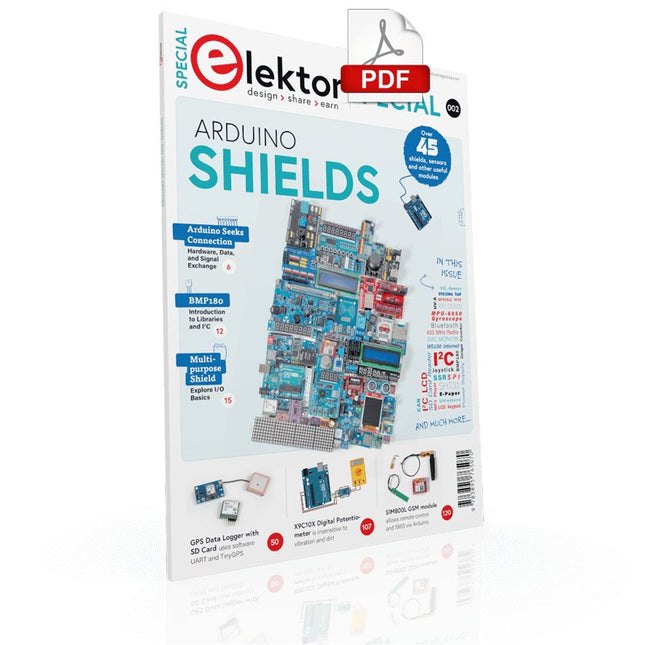
Make your project dreams come true: an odometer for the hamster wheel, a fully automatic control of your ant farm with web interface, or the Sandwich-O-Mat – a machine that toasts and grills sandwiches of your choice.
With the Arduino and the DIY or Maker movement, not only did entry into microcontroller programming become child's play, but a second development also took place: Resourceful developers brought small boards – so-called shields or modules – to the market, which greatly simplified the use of additional hardware. The small modules contain all the important electronic parts to be connected to the microcontroller with a few plug-in cables, eliminating the need for a fiddly and time-consuming assembly on the plug-in board. In addition, it is also possible to handle tiny components that do not have any connecting legs (so-called SMDs).
Projects Discussed
Arduino seeks connection
BMP and introduction to libraries, I²C
Learn I/O basics with the multi-purpose shield
I²C LCD adapter and DOT matrix displays
LCD keypad shield
Level converter
W5100: Internet connection
I/O expansion shield
Relays and solid-state relays
The multi-function shield: A universal control unit
Connecting an SD card reader via SPI
Keys and 7-segment displays
16-bit ADC
MCP4725 DAC
16-way PWM servo driver
MP3 player
GPS data logger using an SD card
Touch sensor
Joystick
SHT31: Temperature and humidity
VEML6070 UV-A sensor
VL53L0X time-of-flight
Ultrasonic distance meter
MAX7219-based LED DOT matrix display
DS3231 RTC
Port expander MCP23017
433 MHz radio
MPU-650 gyroscope
ADXL345 accelerometer
WS2812 RGB LEDs
Power supply
MQ-xx gas sensors
CO2 gas sensor
ACS712 current sensor
INA219 current sensor
L298 motor driver
MFRC522 RFID
28BYJ-48 stepper motor
TMC2209 silent step stick
X9C10x digital potentiometer
ST7735 in a color TFT display
e-Paper display
Bluetooth
Geiger counter
SIM800L GSM module
I²C multiplexer
Controller Area Network
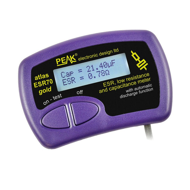
The Peak Atlas ESR70 gold is an enhanced version of the previous Peak Atlas ESR70 Plus. It does everything that the ESR70 Plus did but better.
It now measures capacitance up to 10x faster, and over a wider range, thanks to new test algorithms. The capacitance measurement is also much less influenced by parallel resistances or leakage current thanks to our new Triple-Slope measurement system.
Using the supplied gold plated probes (removable), the Atlas ESR70 gold can measure ESR down to a resolution of 0.01 ohms, up to 40 ohms. It can even measure ESR for capacitors that are in-circuit. Probes are removable, allowing 2 mm compatible probes to be fitted. Audible alerts are produced for various ESR levels allowing you to perform many tests in succession without having to look at the display. The ESR70 automatically takes capacitive reactance into account, so even low value capacitors (down to 0.3 uF) can have the ESR measured accurately.
Features
Uses a single AAA Alkaline cell (included)
Alphanumeric LCD with backlight
Automatic analysis-start when you apply the probes
Automatic capacitor discharge using controlled discharge function
ESR (and low DC resistance) measurement (even in-circuit)
Capacitive reactance automatically taken into account to ensure accurate ESR
Capacitance measurement (if testing out-of-circuit)
Audible alerts for various ESR levels
Extended ESR measurement range up to 40 Ohms
Optional probe alternatives easily fitted
New gold Features
Improved LCD with better backlight
10x faster capacitance measurement for large capacitors
Enhanced user options system
New triple-slope measurement system to vastly reduce the influence of parallel resistance and/or leakage current on capacitance measurements
Much wider capacitance measurement range now 0.3 uF to 90,000 uF (was 1uF to 22,000uF)
Specifications
Analyzer type
ESR and Capacitance
Component types
Capacitors (>0.3 uF)
ESR range
0.00 Ohms to 40.0 Ohms
ESR resolution
From 0.01 Ohms
In-circuit use
ESR only
Capacitance range
0.3 uF to 90000 uF
Battery type
1.5 V Alkaline AAA Cell (supplied). Life typically 1500 ops
Display type
Alphanumeric LCD (with backlight)
Included
Peak Atlas ESR70 gold
Extra-long and extra-flexible test cables (450 mm of Silicone covered cable)
2 mm gold plated plugs and sockets with removeable gold plated crocodile clips
Comprehensive illustrated user guide
AAA Alkaline cell
Downloads
Datasheet (EN)
User Guide (EN)
User Guide (FR)
User Guide (IT)
Kick off with the MAX1000 and VHDPlus
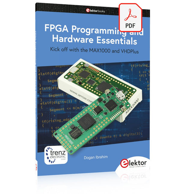
Ready to Master FPGA Programming? In this guide, we’re diving into the world of Field Programmable Gate Arrays (FPGAs) – a configurable integrated circuit that can be programmed after manufacturing. Imagine bringing your ideas to life, from simple projects to complete microcontroller systems!
Meet the MAX1000: a compact and budget-friendly FPGA development board packed with features like memory, user LEDs, push-buttons, and flexible I/O ports. It’s the ideal starting point for anyone wanting to learn about FPGAs and Hardware Description Languages (HDLs).
In this book, you’ll get hands-on with the VHDPlus programming language – a simpler version of VHDL. We’ll work on practical projects using the MAX1000, helping you gain the skills and confidence to unleash your creativity.
Get ready for an exciting journey! You’ll explore a variety of projects that highlight the true power of FPGAs. Let’s turn your ideas into reality and embark on your FPGA adventure – your journey starts now!
Exciting Projects You’ll Find in This Book
Arduino-Driven BCD to 7-Segment Display Decoder
Use an Arduino Uno R4 to supply BCD data to the decoder, counting from 0 to 9 with a one-second delay
Multiplexed 4-Digit Event Counter
Create an event counter that displays the total count on a 4-digit display, incrementing with each button press
PWM Waveform with Fixed Duty Cycle
Generate a PWM waveform at 1 kHz with a fixed duty cycle of 50%
Ultrasonic Distance Measurement
Measure distances using an ultrasonic sensor, displaying the results on a 4-digit 7-segment LED
Electronic Lock
Build a simple electronic lock using combinational logic gates with push buttons and an LED output
Temperature Sensor
Monitor ambient temperature with a TMP36 sensor and display the readings on a 7-segment LED
Downloads
Software
Principles, Design, and Real-World Applications of Modern Photonics
Light shapes our world—from the glow of a simple LED to the precision of a laser beam and the immense power of the sun. LEDs, Lasers, and Sunlight – Principles, Design, and Real-World Applications of Modern Photonics is your comprehensive guide to understanding, designing, and applying modern light technologies.
This book takes you on a journey from the fundamentals of photonics—covering the nature of light, optical laws, and color theory—to real-world engineering with today’s most important light sources. You’ll explore how LEDs work, how to design efficient lighting systems, and how to tackle practical challenges such as thermal management, power supply design, and optical performance.
Beyond illumination, the book opens doors to specialized applications: horticultural lighting for plant growth, infrared and ultraviolet technologies, modern display systems from LCD to MicroLED, and the fascinating world of lasers—from their physics to their use in medicine, industry, and communication. It also connects light engineering to sustainability through solar energy and thermal radiation.
Written with a strong practical focus, this book bridges theory and application. Whether you are an engineer, student, or advanced hobbyist, you’ll gain the tools to turn concepts into working solutions—from selecting components to building complete systems.
If you want to understand light not just as a phenomenon, but as a powerful engineering tool, this book will illuminate the way.
Diese Ausgabe steht allen GOLD- und GREEN-Mitgliedern auf der ElektorMagazine-Website zum Download bereit!
Sie sind noch kein Mitglied? Hier klicken!
Relio v1.0 – Anwesenheitserkennung und FernsteuerungEin Matter-fähiger Smart-Controller für Hausgeräte
Bessere Leiterplatten entwerfenEin praxisnaher Leitfaden für Profis und Maker
KiCad 9Die wichtigsten neuen und aktualisierten Funktionen
Präzisions-Picoamperemeter (Teil 1)Mit Kennlinienschreiber-Funktion bis in den pA-Bereich
Analoger Pipeline-VerzerrerEin cooler Audioeffekt für Gitarren und andere Instrumente
Halogene in LötmittelnFakten statt Mythen
100-mV-Durchgangsprüfer
Wer treibt die europäische Elektronik voran?Unternehmen im Fokus
productronica 2025Neuheiten in Elektronikentwicklung und -fertigung
Automatisierung bewältigt Herausforderungenwie Reshoring, Zölle und Arbeitskräftemangel
Mehr als ZukunftssicherheitKreislaufwirtschaft in der Elektronik
Passive BauelementeVerlustarme Induktivitäten für hocheffiziente DC/DC-Wandler
PCB-Produktion im WandelDesktop-Maschinen eröffnen neue Wege für die Leiterplattenfertigung
Aller Anfang ...... braucht Spannung
UHD-Displays mühelos ansteuernIhr Leitfaden, um unterschiedliche TFT-LCDs schnell in Betrieb zu nehmen
Löten im Jahr 2025Praktische Tipps direkt von der Werkbank
Weihnachtsstern 2025Ein Stern wird gelötet
SimulIDEEin All-in-One-Werkzeug für die Schaltungsentwicklung
2025: Eine KI-OdysseeVom Autovervollständiger zum Kollegen
Wortreicher WeihnachtsbaumEin festliches Elektronikprojekt mit verbalem Highlight
Projekt 2.0Korrekturen, Updates und Leserbriefe
ESP32-Audio-Transceiver-Board (Teil 3)Stereosender und Dual Radio
Diese Ausgabe steht allen GOLD- und GREEN-Mitgliedern auf der ElektorMagazine-Website zum Download bereit!
Sie sind noch kein Mitglied? Hier klicken!
Kleine WärmebildkameraRealisiert mit einem Arduino UNO
Projekt-Update #3: Energiemessgerät mit ESP32Integration und Test mit Home Assistant
2024: Eine Odyssee in die KIVerbessern der Objekterkennung: Nutzung verfeinerter Techniken
Raspberry Pi Goes KINeues Kit enthält M.2-HAT mit KI-Beschleuniger
Sensoren für WetterstationenWelchen Sensor sollte man wählen?
KI-gestützter WasserzählerTeil 1: Bringen Sie Ihren alten Zähler ins IoT!
Ein GSM-AlarmNutzung der GSM-Technologie für die Fernüberwachung von Garagen
Low-Power-Thread-Geräte optimiert und getestetNiedriger Energiebedarf ... Niedrige Leistung?
Aus dem Leben gegriffenDer Gender-Gap
Nebelkammer selbstgebautUnsichtbare Strahlung sichtbar machen
SparkFun Thing Plus MatterEin vielseitiges Matter-basiertes IoT-Entwicklungsboard
IoT-RetrofittingRS232-Geräte fit für Industrie 4.0 machen
IoT mit 8-Bit-Mikrocontrollern
Technologie als Motor der NachhaltigkeitNeuerungen führen zu Energieeffizienz in vielen Applikationen
AWS für Arduino und Co.Teil 1: AWS-IoT-ExpressLink in der Praxis
Luftstromdetektor (nur) mit ArduinoKeine externen Sensoren erforderlich!
WasserleckdetektorVerbunden mit der Arduino-Cloud
QuarzeBemerkenswerte Bauteile
Universeller Garten-LoggerEin Schritt auf dem Weg zur KI-gestützten Gartenarbeit
Analoger 1-kHz-GeneratorSinuswellen mit geringen Verzerrungen
Miletus: Web-Apps offline nutzenSystem- und Gerätezugriff inklusive
Von 4G zu 5GIst es wirklich so einfach?
Aller Anfang...muss nicht schwer sein: Der Ausgleich
The OWON SDS1102 is an affordable benchtop digital oscilloscope that combines solid performance with essential measurement features. This 2-channel oscilloscope offers a 100 MHz bandwidth, a 1 GS/s sampling rate, a 7-inch LCD display, and a 10 kpts memory depth, making it a practical choice for everyday electronics testing, troubleshooting, and education.
The SDS1102 features a simplified trigger system with level and edge triggering, making it easy to capture and analyze common signals. It is designed for applications that do not require deep memory or advanced trigger functions, offering a straightforward and cost-effective solution for basic signal analysis.
Features
Bandwidth: 100 MHz
2 channels
Sample rate: 1 GS/s
Ultra-thin body
7-inch high-res LCD
SCPI and LabVIEW supported
Specifications
Bandwidth
100 MHz
Horizontal Scale (s/div)
5 ns/div – 1000 s/div
Channel
2
Vertical Sensitivity
5 mV/div – 5 V/div (at input)
DC Gain Accuracy
3%
Vertical Resolution (A/D)
8 bits (2 channels simultaneously)
Input
Input Impedance
1 MΩ, 10 pF
Input Coupling
AC, DC, GND
Max Input Voltage
±400 V, CATI, CATII
Passive probes
х1; х10
Probe Attenuation Factor
х1; х10; х100; х1000
Trigger System
Trigger Mode
Auto, Normal, Single
Trigger Type
Edge, Video
Edge Trigger Source
CH1, CH2
Video Trigger
Sampling Type
Real-time
Sample Rate
1 GS/s
Equivalent Sample Rate
No
Wavelength
10K pts
Interpolation
sin(x)/x
Measurement and Mathematical Treatment System
Automatic Measurement
Vpp, Vavg, RMS, Frequency, Period, Vmax, Vmin, Vtop, Vbase, Width, Overshoot, Pre-shootRise time, Fall time, +Width, -Width, +Duty, -Duty, Delay A→B, Delay A→B, area, cycle area
Math Functions
Addition, Subtraction, Multiplication, Division, FFT
General Characteristics
Display type
7" color LCD
Display Resolution
800 x 480
Power
100-240 V, 45-440 Hz, <15 W
Dimensions
301 x 70 x 152 mm
Weight
1.1 kg
Included
1x OWON SDS1102 Oscilloscope
2x Oscilloscope probes
1x Probe adjust
1x Mains power cord
1x USB cable
1x CD-Rom
1x Quick guide
Downloads
Quick Guide
Manual
PC Software
SCPI Commands
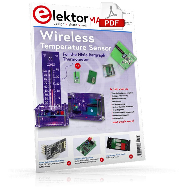
USB to S/PDIF InterfaceDigital audio output for computer, laptop, tablet or smartphone
Practical ESP32 Multitasking (4)Binary semaphores
A Wireless Temperature Sensor for the Nixie Bargraph ThermometerA multipurpose solution with a design trick
Multitasking with Raspberry PiShowcase: a traffic lights controller
Timer for Headphone Amplifier
Open-Network Weather Station Mk.2Part 2: Software
Home Automation Made EasyWith ESPHome, Home Assistant & MySensors
The Storage CRTPeculiar Parts, the series
Artificial Intelligence for Beginners (3)A stand-alone neural network
Programming PICs from the Ground UpAssembler routine to output a sine wave
IKEA Lamp HackEquipping an inexpensive IKEA lamp with NeoPixel LEDs and WLAN
Don't Let Your Hobby Project Collect Dust in a CornerSupply-side time management and spiral development
Starting Out in Electronics (4)Easier than imagined!
Homelab Tours: The Vinyl CutterReturning to the golden age of LPs
The 8-Bit Microcontroller and BeyondInterview with Tam Hanna
Small Circuits RevivalFrom the Elektor suggestions box
Review: Owon OW18E Bluetooth Multimeter
InteractiveCorrections & Updates || Questions & Answers
Steeped in ElectronicsLead-free soldering and EU regulatory zeal
Promising Project: New 50 Hz – 2 MHz LCR meterAccuracy and ease of use
Error AnalysisTips on FMEA, High Current, and More
Developer's ZoneTips & Tricks, Best Practices and Other Useful Information
Review: Siglent SDL1020X Programmable DC Electronic Load
High-Voltage Power Supply with Curve TracerGenerate voltages up to 400 V and trace characteristics curves for valves and transistors
Hexadoku 2009EL
Analogue Electronics DesignCase Study #2 — Part 1: Analogue filter theory
The Elektor StoreNever expensive, always surprising
How to Draw a Circuit Diagram
STmicroelectronics’ wireless IoT & wearable sensor development kit
‘SensorTile.box’ is a portable multi-sensor circuit board housed in a plastic box and developed by STMicroelectronics. It is equipped with a high-performance 32-bit ARM Cortex-M4 processor with DSP and FPU, and various sensor modules, such as accelerometer, gyroscope, temperature sensor, humidity sensor, atmospheric pressure sensor, microphone, and so on. SensorTile.box is ready to use with wireless IoT and Bluetooth connectivity that can easily be used with an iOS or Android compatible smartphone, regardless of the level of expertise of the users. SensorTile.box is shipped with a long-life battery and all the user has to do is connect the battery to the circuit to start using the box.
The SensorTile.box can be operated in three modes: Basic mode, Expert mode, and Pro mode. Basic mode is the easiest way of using the box since it is pre-loaded with demo apps and all the user has to do is choose the required apps and display or plot the measured data on a smartphone using an app called STE BLE Sensor. In Expert mode users can develop simple apps using a graphical wizard provided with the STE BLE Sensor. Pro mode is the most complex mode allowing users to develop programs and upload them to the SensorTile.box.
This book is an introduction to the SensorTile.box and includes the following:
Brief specifications of the SensorTile.box; description of how to install the STE BLE Sensor app on an iOS or Android compatible smartphone required to communicate with the box.
Operation of the SensorTile.box in Basic mode is described in detail by going through all of the pre-loaded demo apps, explaining how to run these apps through a smartphone.
An introduction to the Expert mode with many example apps developed and explained in detail enabling users to develop their own apps in this mode. Again, the STE BLE Sensor app is used on the smartphone to communicate with the SensorTile.box and to run the developed apps.
The book then describes in detail how to upload the sensor data to the cloud. This is an important topic since it allows the sensor measurements to be accessed from anywhere with an Internet connection, at any time.
Finally, Pro mode is described in detail where more experienced people can use the SensorTile.box to develop, debug, and test their own apps using the STM32 open development environment (STM32 ODE). The Chapter explains how to upload the developed firmware to the SensorTile.box using several methods. Additionally, the installation and use of the Unicleo-GUI package is described with reference to the SensorTile.box. This PC software package enables all of the SensorTile.box sensor measurements to be displayed or plotted in real time on the PC.