
Search results for "epaper OR 2 OR 0 OR display OR 160097 OR 71"
-

QuantAsylum QuantAsylum QA403 24-bit Audio Analyzer
The QA403 is QuantAsylum's fourth-generation audio analyzer. The QA403 extends the functionality of the QA402 with improved noise and distortion performance, in addition to a flatter response at band edges. The compact size of the QA403 means you can take it just about anywhere. Features 24-bit ADC/DAC Up to 192 kS/s Fully isolated from PC Differential Input/Output USB powered Built-in Attenuator Fast Bootup and Driverless The QA403 is a driverless USB device, meaning it’s ready as soon as you plug it in. The software is free and it is quick and easy to move the hardware from one machine to the next. So, if you need to head to the factory to troubleshoot a problem or take the QA403 home for a work-from-home day, you can do it without hassle. No-Cal Design The QA403 comes with a factory calibration in its flash memory, ensuring consistent unit-to-unit performance. On your manufacturing line you can install another QA403 and be confident what you read on one unit will be very similar to the next unit. It is not expected that re-calibration will be required at regular intervals. Measurements Making basic measurements is quick and easy. In a few clicks you will understand the frequency response, THD(+N), gain, SNR and more of your device-under test. Dynamic Range The QA403 offers 8 gain ranges on the input (0 to +42 dBV in 6 steps), and 4 gain ranges on the output (-12 to +18 dBV in 10 dB steps). This ensures consistent performance over very wide ranges of input and output levels. The maximum AC input to the QA403 is +32 dBV = 40 Vrms. The maximum DC is ±40 V, and the maximum ACPEAK + DC = ±56 V. Easy Programmability The QA403 supports a REST interface, making it easy to automate measurements in just about any language you might anticipate. From Python to C++ to Visual Basic—if you know how to load a web page in your favorite language, you can control the QA403 remotely. Measurements are fast and responsive, usually with dozens of commands being processed per second. Isolated and USB Powered The QA403 is isolated from the PC, meaning you are measuring your DUT and not chasing some phantom ground loop. The QA403 is USB powered, like nearly all our instruments. If you are setting up remotely, throw a powered hub in your bag and your entire test setup can be running with a minimum of cables. Goodbye Soundcard, Hello QA403 Tired of trying to make a soundcard work? The calibration nightmare? The lack of gain stages? The limited drive? Are you tired of dealing with the fixed input ranges? The worry that you might destroy it with too much DC or AC? Tired of the ground loops? That’s why QuantAsylum built the QA403. Specifications Case Material Powder-coating Aluminum (2 mm thick front panel, 1.6 mm thick top/bottom) Dimensions 177 x 44 x 97 mm (W x H x D) Weight 435 g Downloads Datasheet Manual GitHub
-
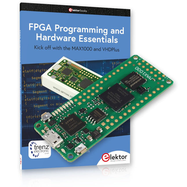
Elektor Bundles MAX1000 FPGA Programming Bundle
Kick off to FPGA Programming with the MAX1000 Board and VHDPlus Ready to master FPGA programming? With this bundle, you'll dive into the world of Field-Programmable Gate Arrays (FPGAs) – a configurable integrated circuit that can be programmed after manufacturing. Bring your ideas to life, from simple projects to complete microcontroller systems! The MAX1000 is a compact and powerful FPGA development board packed with features like memory, user LEDs, push-buttons, and flexible I/O ports. It’s the ideal starting point for anyone wanting to learn about FPGAs and Hardware Description Languages (HDLs). With the enclosed book "FPGA Programming and Hardware Essentials" you'll get hands-on with the VHDPlus programming language – a simpler version of VHDL. You'll work on practical projects using the MAX1000, helping you gain the skills and confidence to unleash your creativity. Projects in the Book Arduino-driven BCD to 7-Segment Display Decoder Use an Arduino Uno R4 to supply BCD data to the decoder, counting from 0 to 9 with a one-second delay Multiplexed 4-Digit Event Counter Create an event counter that displays the total count on a 4-digit display, incrementing with each button press PWM Waveform with Fixed Duty Cycle Generate a PWM waveform at 1 kHz with a fixed duty cycle of 50% Ultrasonic Distance Measurement Measure distances using an ultrasonic sensor, displaying the results on a 4-digit 7-segment LED Electronic Lock Build a simple electronic lock using combinational logic gates with push buttons and an LED output Temperature Sensor Monitor ambient temperature with a TMP36 sensor and display the readings on a 7-segment LED MAX1000 FPGA Development Board The MAX1000 is a customizable IoT/Maker Board ready for evaluation, development and/or use in a product. It is built around the Intel MAX10 FPGA, which is the industry’s first single chip, non-volatile programmable logic device (PLDs) to integrate the optimal set of system components. Users can now leverage the power of tremendous re-configurability paired with a high-performance, low-power FPGA system. Providing internally stored dual images with self-configuration, comprehensive design protection features, integrated ADCs and hardware to implement the Nios II 32-bit microcontroller IP, MAX10 devices are ideal solution for system management, protocol bridging, communication control planes, industrial, automotive and consumer applications. The MAX1000 is equipped with an Arrow USB Programmer2, SDRAM, flash memory, accelerometer sensor and PMOD/Arduino MKR connectors making it a fully featured plug and play solution without any additional costs. Specifications MAX 10 8 kLE - Flash Dual inside - ADC 8x 12 Bit - Temperature Range 0~85°C - Supply USB/pins SDRAM 8 MB 3-axis MEMS LIS3DH USB Programmer on board MEMS Oscillator 12 MHz Switch/LED 2x / 8x Contents of the Bundle Book: FPGA Programming and Hardware Essentials (normal price: €40) MAX1000 FPGA Development Board (normal price: €45) Downloads Software
-

SunFounder SunFounder Kepler Kit (Ultimate Starter Kit for Raspberry Pi Pico W)
Your gateway to IoT and microcontroller programming With 450+ components and 117 online projects, this comprehensive kit ignites your creativity. The tutorials by Paul McWhorter make learning enjoyable for beginners and advanced users. This kit supports MicroPython, C/C++, and Piper Make, offering diverse programming options. Explore sensors, actuators, LEDs, and LCDs for endless project possibilities. From home automation to robotics, this kit empowers your tech journey. Features IoT Starter Kit for Beginners: This kit offers a rich IoT learning experience for beginners. With 450+ components, 117 projects, and expert-led video lessons, this kit makes learning microcontroller programming and IoT engaging and accessible. Expert-Guided Video Lessons: The kit includes 27 video tutorials by the renowned educator, Paul McWhorter. His engaging style simplifies complex concepts, ensuring an effective learning experience in microcontroller programming. Wide Range of Hardware: The kit includes a diverse array of components like sensors, actuators, LEDs, LCDs, and more, enabling you to experiment and create a variety of projects with the Raspberry Pi Pico W. Supports Multiple Languages: The kit offers versatility with support for three programming languages - MicroPython, C/C++, and Piper Make, providing a diverse programming learning experience. Dedicated Support: Benefit from our ongoing assistance, including a community forum and timely technical help for a seamless learning experience. Included Raspberry Pi Pico W Breadboard Jumper Wires Resistor Transistor Capacitor Diode Li-po Charger Module 74HC595 TA6586 – Motor Driver Chip LED RGB LED LED Bar Graph 7-segment Display 4-Digit 7-Segment Display LED Dot Matrix I²C LCD1602 WS2812 RGB 8 LEDs Strip Buzzer DC Motor Servo DC Water Pump Relay Button Micro Switch Slide Switch Potentiometer Infrared Receiver Joystick Module 4x4 Keypad MPR121 Module MFRC522 Module Photoresistor Thermistor Tilt Switch Reed Switch PIR Motion Sensor Module Water Level Sensor Module Ultrasonic Module DHT11 Humiture Sensor MPU6050 Module Documentation Online Tutorials in 3 languages (EN, DE and JP)
-

NXP Semiconductors NXP FRDM-MCXN947 Development Board
The FRDM-MCXN947 is a compact and versatile development board designed for rapid prototyping with MCX N94 and N54 microcontrollers. It features industry-standard headers for easy access to the MCU's I/Os, integrated open-standard serial interfaces, external flash memory, and an onboard MCU-Link debugger. Specifications Microcontroller MCX-N947 Dual Arm Cortex-M33 cores @ 150 MHz each with optimized performance efficiency, up to 2 MB dual-bank flash with optional full ECC RAM, External flash Accelerators: Neural Processing Unit, PowerQuad, Smart DMA, etc. Memory Expansion *DNP Micro SD card socket Connectivity Ethernet Phy and connector HS USB-C connectors SPI/I²C/UART connector (PMOD/mikroBUS, DNP) WiFi connector (PMOD/mikroBUS, DNP) CAN-FD transceiver Debug On-board MCU-Link debugger with CMSIS-DAP JTAG/SWD connector Sensor P3T1755 I³C/I²C Temp Sensor, Touch Pad Expansion Options Arduino Header (with FRDM expansion rows) FRDM Header FlexIO/LCD Header SmartDMA/Camera Header Pmod *DNP mikroBUS User Interface RGB user LED, plus Reset, ISP, Wakeup buttons Included 1x FRDM-MCXN947 Development Board 1x USB-C Cable 1x Quick Start Guide Downloads Datasheet Block diagram


