Inhalt
Grundlagen
Kathodengegenkopplung – bei Endröhren durch eine Übertragerwicklung
Der Zwischenübertrager
Bauanleitungen
Eintakt-A-Endstufe mit 4x 6V6 – 6V6 quatroSE – ernsthafter Eintakter mit 16 W, nicht nur für hocheffiziente Lautsprecher
CD-Vorverstärker mit CD-Filter
Moderne Hybridendstufe
Die Kathedrale in der Streichholzschachtel – Elektronische Hallspirale
UKW-Mischteil – mit der Doppeltriode ECC2000 und der Triode/Pentode ECF80
Technik
In die Röhre geschaut – Computer-tomografische Bilder vom Röhreninneren
6L6GC – with best Regards from the United States of America
Röhrensockel
Info
Die Röhren-Sonderheft-Reihe hat die runde Zahl 10 erreicht
Nachruf Jan Jurco – Gründer von JJ Electronic
Buchbesprechung
Röhrendaten
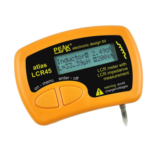
The Peak Atlas LCR45 does everything that the popular LCR40 does, but it has some significant enhancements. The LCR45 features a new high capacity micro and high resolution ADCs.
LCR45 incorporates advanced maths, based on Complex Impedance analysis. This allows for enhanced component value measurement as well as a comprehensive and detailed impedance display.
Features
Supplied with gold plated removable hook probes
Fluid measurements with hold function
Automatic or manual component type
Automatic or manual test frequency, DC, 1 kHz, 15 kHz or 200 kHz
Enhanced measurement resolution: 0.2 µH, 0.2 pF and 0.2 Ohms
Easy menu system for user settings
Enhanced compensation for component parasitics and losses (such as core losses etc)
Automatic or manual power-off
Specifications
Analyser type
LCR and component impedance
Component types
Auto/Manual for L,C & R
Measurement types
Inductance, Capacitance and Resistance
Other measurements
Complex impedance/admittance
More measurements
Magnitude and Phase of impedance
Inductance range
0uH to 2H
Capacitance range
0 pF to 10000 uF
Resistance range
0R to 2MR
Test frequency
Auto and manual: DC, 1 kHz, 15 kHz, 200 kHz
Display type
Alphanumeric LCD (not backlit)
Measurement scheme
Continuous (with optional hold)
Battery
GP23 (12 V/55 mAH type), ~700 ops
Included
LCR45 Passive Component Impedance Meter
2 mm plugs and sockets and removeable hook probes
Comprehensive illustrated user guide
2 Batteries, one installed and one spare. GP23 Alkaline battery. (12 V/55 mAH)
Downloads
Datasheet (EN)
User Guide (EN)
User Guide (FR)
User Guide (IT)
Programming with GNU Radio
HackRF is an open-source hardware platform developed by Great Scott Gadgets and serves as a versatile front end for software-defined radio (SDR). With HackRF One and its successor, HackRF Pro, users can develop their own SDR applications, build powerful receivers and transmitters, and tackle demanding RF measurement tasks.
This book provides a practical introduction to the world of SDR. Step by step, the author shows how powerful SDR projects can be implemented with HackRF – from the fundamentals of RF technology to advanced applications using GNU Radio.
In addition to working with SDR Sharp (SDR#), RadioConda, and GNU Radio, the book also covers the fundamentals of modern digital signal processing. Numerous experiments and easy-to-follow practical examples guide readers through topics such as AM, FM, and SSB reception, digital filters, shortwave radio, amateur radio, signal generators, and custom RF projects up to 6 GHz.
Whether you are a maker, radio amateur, electronics enthusiast, or SDR beginner, this book provides solid knowledge, practical applications, and the motivation to creatively explore the possibilities of modern SDR technology.
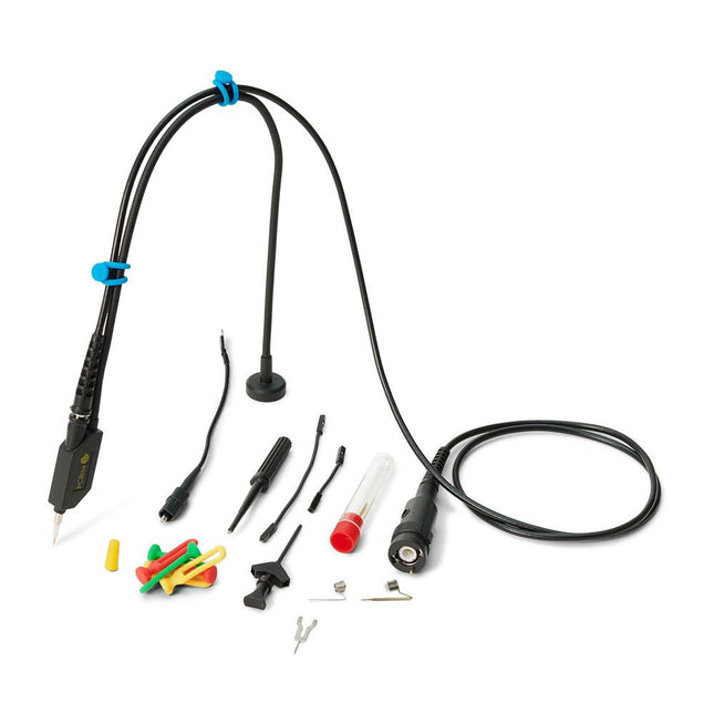
The SQ series of handsfree probes from Sensepeek have a lower point of gravity making them even more stable compared with the original SP series of handsfree probes. All probes in the SQ series are also insulated and can be used handheld as any traditional probe but their full potential is used when measuring handsfree.
The SQ series of oscilloscope probes also includes more ground options, have probe tip protection, longer cable and support for oscilloscopes with automatic scaling (10:1).
All the loved features of handsfree measurement, exchangeable fine pitch spring tipped test needle, color-coded cable holders and the minimalistic design is maintained to make traditional sized and handheld probes obsolete.
Both length and weight of the SQ probes are perfectly balanced to be used with PCBite PCB holders and base plate which is a must for handsfree function.
Features
Passive 10:1 probe with support for oscilloscopes with automatic scaling
Spring-loaded test needle for fine pitch measurements
Multiple ground options
Color coded cable holders
Probe tip protection
Insulated, can be used handheld
Improved probe holder for handsfree measurement when used with PCBite PCB holders
Included
1x SQ350 350 MHz probe with spring tipped test needle
1x SQ probe holder for handsfree measurement
1x Testhook with detachable cables (5 cm & 10 cm) for convenient ground connection
1x Alligator cable for convenient ground connection
1x Standard ground spring, for handheld measurements at rated bandwidth
1x Unique ground spring, for total handsfree measurements at rated bandwidth
1x Set of color coded cable holders (4 colors)
1x Probe tip protection
1x Extra test needle
Downloads
User Guide SQXX0 Rev1.1
Aus dem Inhalt
Kompakter High-End-Vollverstärker mit PCL 86
Schaltungen mit der neuen Röhre EL 84 T als echte Triode
UKW Stereo-Empfänger in Hybrid-Technik
Frequenzanzeige für UKW-Tuner mit Nixie-Röhren
Kompaktes Labornetzteil zur Entwicklung von Röhrenschaltungen
Symmetrix – Vollsymmetrische Endstufe für hochwertigen Hifi- und Studioeinsatz
Hybridendstufe
Röhrenkennlinien aufnehmen mit dem PC
Röhrenvoltmeter
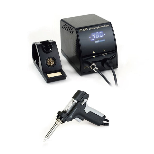
The ZD-8965 is a digital temperature-controlled desoldering station equipped with ground protection and an LCD screen for temperature display. Despite its compact and robust design, this high-power desoldering station is easy to operate with just one hand.
The ZD-8965 features a soldering gun with an integrated filter that captures any extracted material, allowing for continuous operation by simply replacing the filters. Additionally, a temperature sensor is embedded in the tip, enabling rapid response to temperature fluctuations for consistent performance.
Features
Effortlessly adjust the temperature between 160°C and 480°C using the convenient up/down buttons on the front panel.
LED display to indicate the temperature in °C/°F
Features an ergonomic pistol grip with a trigger for quick and efficient solder waste removal.
The upgraded soldering gun includes a rear trigger, making it exceptionally convenient for replacing and cleaning components.
Comes with a high-quality soldering gun and a sturdy holder.
Equipped with a heavy-duty heater that ensures optimal desoldering performance every time.
Specifications
Station
Voltage supply
220-240 V
Power
140 W
Vakuum pressure
600 mm HG
Desoldering Gun
Power
140 W (18 V DC)Heat up rating: 140 W
Temperature
160-480°C (320-896°F)
Heating element
Ceramic heater
Included
1x ZD-8965 Desoldering station
2x Spare soldering tips
3x Cleaning needles for desoldering tips
3x Spare filter for desoldering gun
1x Spare filter for desoldering station
1x Manual
Diese Ausgabe steht allen GOLD- und GREEN-Mitgliedern auf der ElektorMagazine-Website zum Download bereit!
Sie sind noch kein Mitglied? Hier klicken!
DIY-SolarakkusÜber den Selbstbau von Energiespeichern für Solaranlagen
Solarmodul-SimulatorFür Test und Optimierung von MPP-Trackern und Invertern
Der STM32-Edge-KI-WettbewerbEntdecken Sie den neuen STM32N6 und nehmen Sie am Wettbewerb um 5.000 € teil!
Erweiterung der BandlückeWarum gibt es so viel Interesse an SiC und GaN?
Power-Bank für NotebooksVerlängern Sie das Leben Ihres alten Laptops!
Medizinische RoboterÜberwindung technischer und regulatorischer Hürden
Frostwächter für ObstpflanzenMit Temperatur-Datenlogger
Das analoge DingDer Arduino des Analog-Computings?
Sparsames NetzrelaisMit über 90% Leistungsreduzierung
Verbesserung der DC-Last ET5410A+Keep cool and be quiet!
electronica 2024 im Rückblick
Elektromagnetische VerträglichkeitEMV kurz und bündig!
Aller Anfang......muss nicht schwer sein: Aktive Filter
Verlustleistung reduzieren mit AbleitkondensatorenEin cleverer Einsatz von kapazitiver Reaktanz
Preiswerter 12-Bit-Digital-Analog-Wandler MCP4725Mit EEPROM-Feature für sicheres Einschaltverhalten
Fnirsi LCR-ST1, die intelligente LCR-SMD-Pinzette
Test- und Messlabor mit Raspberry PiDas Wichtigste zuerst: Der ADC
Elektronischer LastwiderstandEin Projekt aus der Kiste
2025: Eine Odyssee in die KIEinige Projekte für das neue Jahr
Projekt-Update: Modulares DC-Leistungsmessgerät AmpVolt v2.0100 Ampere und mehr!
Projekt 2.0
Ethische Transparenz sichtbar gemachtErgebnisse der Umfrage 2024 von Ethics in Electronics
Elektor Audio-DSP FX-Prozessor-BoardTeil 2: Anwendungen erstellen
The FNIRSI SG-003A multi-functional Signal Generator a.k.a. Process Meter/Calibrator is a high-precision voltage/current generator and meter. The SG-003A provides highly accurate reference voltages or currents for testing and calibrating other measurement instruments like multimeters and oscilloscopes.
Besides voltages and currents, the SG-003A also generates rectangular pulse signals with precisely programmable frequencies and duty cycles. Its converter mode turns the SG-003A into a precision voltage-controlled current source, or current-controlled voltage source, and even a voltage- or current-controlled frequency generator.
The SG-003A is a great tool for checking your multimeter’s accuracy and precision, and for testing e.g. LEDs.
Features
Accuracy (voltage/current)
0.1% ±0.005
Resolution (current)
0.01 mA
Frequency
0-10 kHz
Resolution
5 digits
Output power
24 V
Display
2.4" TFT LCD (320 x 240)
Dimensions
92 x 72 x 30 mm
Weight
165 g
Specifications
Signal
Range
Precision
Resolution
Max load
External power supply
Active current output
0~24 mA
±(0.1% + 0.005)
0.01 mA
750 Ω
Passive current output (XMT)
0~24 mA
±(0.1% + 0.005)
0.01 mA
0~30 V
Voltage output
0~24 V
±(0.1% + 0.005)
0.01 V
24 V loop
0~24 mA
±(0.1% + 0.005)
0.01 mA
Frequency output
0~9999 Hz
±2%
5 digits
Current input
0~24 mA
±(0.1% + 0.005)
0.01 mA
Voltage input
0~30 V
±(0.1% + 0.005)
0.01 V
Included
1x FNIRSI SG-003A Signal generator
4x Test clips
1x USB charger
1x USB-C cable
1x Manual
Downloads
Manual
Firmware V4.3
Principles, Systems, and Electronics
This handbook provides a detailed study of the sensors and actuators at the heart of modern vehicle electronics. It begins with basic electrical and electronic concepts, introducing the principles and terminology essential for understanding automotive systems.
The book explores sensors and actuators on a system-by-system basis, including:
Fundamentals of electrical engineering, electromagnetic phenomena, and motor principles
Passive and active electronic components, integrated circuits, protection devices, and automotive-grade electronics
Sensor characteristics, signal conditioning, ADCs, PWM and frequency outputs, and interface adaptation
Automotive communication links and protocols, including LIN and SENT
Engine sensors: air mass, pressure, temperature, speed, position, exhaust and emissions-related sensors
Transmission sensors for manual and automatic systems
Steering and suspension sensors for conventional and active systems
Vehicle body and electrical system sensors for comfort, climate, access, and monitoring functions
Engine actuators such as throttle bodies, injectors, turbo actuators, EGR systems, ignition components, and pumps
Transmission, brake, steering, suspension, and body actuators
Identification and coding of electronic components and packages commonly used in automotive applications
The structure and operating principles of each component are explained, with relevant electronic circuitry illustrated. Its system-oriented organization and practical focus make it a valuable reference for understanding, testing, and troubleshooting automotive electronic systems.
Diese Ausgabe steht allen GOLD- und GREEN-Mitgliedern auf der ElektorMagazine-Website zum Download bereit!
Sie sind noch kein Mitglied? Hier klicken!
Der ESP-BLASTEine Mini-Raketendrohne mit ESP32, die über 100 km/h erreicht
Wireless Workshop (1)Freigeschaltetes Funkmodul: 433-MHz-CC1101-Sub-GHz-Transceiver
AM-Sendermit Rechteck-/Sinuswellengenerator auf Raspberry Pi Pico
STM32Cube Innovations ChallengeTreten Sie mit Ihrem besten STM32C5-Design an
CoffeeCallerWie ein langer Flur zu einer maßgefertigten Mesh-Netzwerk-Platine führte
AudiotronicsKlirrfaktor
Elektor ist 65Projekte aus früheren September/Oktober-Ausgaben
Geräteortung durch Bluetooth Channel SoundingZentimetergenaue Entfernungsmessung im IoT der nächsten Generation
2026: Eine KI-OdysseeQuantencomputing ist nicht die nächste GPU
Cloud-Schutz durch Edge-Sicherheit
Erste Erfahrungen mit dem HackRF ProPraktische Tests mit der neuen SDR-Hardware
Herausforderung ElektromobilitätEffiziente Lötlösungen für moderne Fahrzeugtechnik
Modem-Update von GPRS/2G auf LTE/4Gam Beispiel einer Funk-Alarmzentrale
Loop-Antenne mit RF BricksTeil 1: Kurzwellen-Antenne mit einstellbarer Richtwirkung im Selbstbau
Internetradio-zu-AM-KonverterVerwendung eines ESP32-S3 als Sender
Projekt 2.0
mioty – ein ÜberblickLPWAN à la Fraunhofer
Werkbank-WeisheitPraktische Tipps von Experten
Walter, das kompakte IoT-ModulTeil 2: Zugriff auf Wetter- und Datendienste
The OWON SDS1102 is an affordable benchtop digital oscilloscope that combines solid performance with essential measurement features. This 2-channel oscilloscope offers a 100 MHz bandwidth, a 1 GS/s sampling rate, a 7-inch LCD display, and a 10 kpts memory depth, making it a practical choice for everyday electronics testing, troubleshooting, and education.
The SDS1102 features a simplified trigger system with level and edge triggering, making it easy to capture and analyze common signals. It is designed for applications that do not require deep memory or advanced trigger functions, offering a straightforward and cost-effective solution for basic signal analysis.
Features
Bandwidth: 100 MHz
2 channels
Sample rate: 1 GS/s
Ultra-thin body
7-inch high-res LCD
SCPI and LabVIEW supported
Specifications
Bandwidth
100 MHz
Horizontal Scale (s/div)
5 ns/div – 1000 s/div
Channel
2
Vertical Sensitivity
5 mV/div – 5 V/div (at input)
DC Gain Accuracy
3%
Vertical Resolution (A/D)
8 bits (2 channels simultaneously)
Input
Input Impedance
1 MΩ, 10 pF
Input Coupling
AC, DC, GND
Max Input Voltage
±400 V, CATI, CATII
Passive probes
х1; х10
Probe Attenuation Factor
х1; х10; х100; х1000
Trigger System
Trigger Mode
Auto, Normal, Single
Trigger Type
Edge, Video
Edge Trigger Source
CH1, CH2
Video Trigger
Sampling Type
Real-time
Sample Rate
1 GS/s
Equivalent Sample Rate
No
Wavelength
10K pts
Interpolation
sin(x)/x
Measurement and Mathematical Treatment System
Automatic Measurement
Vpp, Vavg, RMS, Frequency, Period, Vmax, Vmin, Vtop, Vbase, Width, Overshoot, Pre-shootRise time, Fall time, +Width, -Width, +Duty, -Duty, Delay A→B, Delay A→B, area, cycle area
Math Functions
Addition, Subtraction, Multiplication, Division, FFT
General Characteristics
Display type
7" color LCD
Display Resolution
800 x 480
Power
100-240 V, 45-440 Hz, <15 W
Dimensions
301 x 70 x 152 mm
Weight
1.1 kg
Included
1x OWON SDS1102 Oscilloscope
2x Oscilloscope probes
1x Probe adjust
1x Mains power cord
1x USB cable
1x CD-Rom
1x Quick guide
Downloads
Quick Guide
Manual
PC Software
SCPI Commands
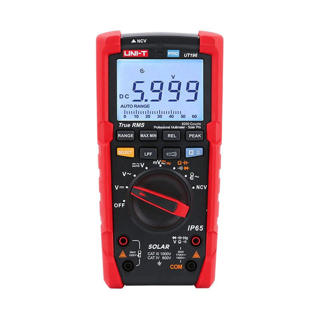
The UT196 True RMS solar multimeter is an ideal tool for solar power system maintenance. This rugged meter is designed for technicians who work in rugged outdoor environments. UT196 can measure up to 1700 V DC and 1500 V AC voltages, and 3000 A AC current with an external current clamp sensor. This solar meter offers IP65 protection and able to withstand 2 m drop as well.
The UT196 solar multimeter is designed with 1700 V DC, 1500 Vrms AC overload protection and tested for safe usage in CAT III 1000 V, CAT IV 600 V environments.
Features
True RMS
Measure up to 1700 V DC and 1500 V AC for high voltage applications e.g. solar array, wind
IP65 protection
CAT III 1000V, CAT IV 600 V
Analog bar
Frequency response: 45 Hz~1 kHz
Low-pass filter function
Low impedance mode
Built-in flashlight, bright backlight and visual alarm
Applications
High DC voltage measurement
Output voltage and frequency measurement
Voltage and frequency measurement
Current and frequency measurement
Specifications
Range
UT196
DC voltage (V)
1700 V
±0.2% +5
AC voltage (V)
1500 V
±0.8% +3
Frequency (Hz)
1 MHz
±0.08% +4
Resistance (Ω)
60 MΩ
±0.8% +2
Capacitance (F)
60 mF
±1.9% +5
Power
9 V battery
Dimensions
195 x 95 x 58 mm
Included
UT196 Solar Multimeter
Battery
Test leads
Downloads
Datasheet
Manual