
Search results for "aktive OR und OR passive OR filter"
-

Elektor Publishing Schnelleinstieg in die Elektronik
Schrittweise Einführung in das praktische Schaltungsdesign Der Einstieg in die Elektronik ist nicht so schwierig, wie man vielleicht denkt. Mit diesem Buch werden die wichtigsten Konzepte der Elektrotechnik und Elektronik auf spielerische Weise erkundet, indem verschiedene Experimente durchgeführt und Schaltungen simuliert werden. Es vermittelt Elektronik praxisnah, ohne in komplexen Fachjargon oder lange Berechnungen einzutauchen. Dadurch werden schon bald eigene Projekte ermöglicht. Es sind keine Vorkenntnisse in Elektronik erforderlich; lediglich einige grundlegende Algebra-Kenntnisse werden in wenigen einfachen Berechnungen verwendet. Viele getestete und funktionierende Projekte und Simulationen werden vorgestellt, um mit dem Aufbau elektronischer Schaltungen vertraut zu werden. Für problemloses Experimentieren – ohne die Gefahr, etwas zu beschädigen – werden zudem frühzeitig auch softwarebasierte Schaltungssimulationen vorgestellt. Lernziele: Konzepte von Spannung, Strom und Leistung Wechselstrom (AC) und Gleichstrom (DC) Grundlegende Lampenschaltungen mit Schaltern Passive Bauteile: Widerstände, Kondensatoren und Induktivitäten RC- und RCL-Schaltungen und Elektromagnetismus Lautsprecher, Relais, Summer und Transformatoren Aktive Bauteile: Dioden und LEDs, Bipolartransistoren und MOSFETs Transistorbasierte Schaltungen Optokoppler-Schaltungen Astabile und monostabile Multivibratoren Verwendung des 555-Timer-ICs Operationsverstärkertechnik Digitale Logik Beispiele: Verstärker, Oszillatoren, Filter und Sensoren Test- und Messwerkzeuge Mikrocontroller: Arduino Uno, ESP32, Raspberry Pi Pico und Raspberry Pi Datenblätter lesen und Auswahl von Komponenten EMV & EMI sowie Normen & Vorschriften
€ 44,80
Best Price
-

Elektor Bundles 555 Timer Projects (Bundle)
This bundle is all about designing projects based on the 555 timer IC. The book features over 45 fully tested and documented projects. Together with the kit, which contains more than 130 through-hole components, you can build all the projects described on a breadboard. The setup also makes it easy to modify and experiment with the projects. Over 45 Builds for the Legendary 555 Chip (and the 556, 558) Some of the projects in the book are: Alternately Flashing Two LEDs Changing LED Flashing Rate Touch Sensor On/Off Switch Switch On/Off Delay Light-Dependent Sound Dark/Light Switch Tone Burst Generator Long Duration Timer Chasing LEDs LED Roulette Game Traffic Lights Continuity Tester Electronic Lock Switch Contact Debouncing Toy Electronic Organ Multiple Sensor Alarm System Metronome Voltage Multipliers Electronic Dice 7-Segment Display Counter Motor Control 7-Segment Display Dice Electronic Siren Various Other Projects Kit Contents Resistors 1x 15 kΩ 1x 68 kΩ 2x 47 kΩ 1x 82 kΩ 2x 820 Ω 1x 8.2 kΩ 3x 10 kΩ 1x 1.8 kΩ 1x 6.8 kΩ 14x 2.2 kΩ 10x 680 Ω 1x 27 kΩ 1x 5.6 kΩ 1x 560 kΩ 1x 4.7 kΩ 1x 3.3 kΩ 3x 33 kΩ 1x 36 kΩ 2x 100 kΩ 5x 1 kΩ 1x 3.9 kΩ 2x 56 kΩ 2x 12 kΩ 1x 10 kΩ potentiometer 1x 1 MΩ potentiometer 2x 50 kΩ potentiometer 3x 20 kΩ potentiometer 1x 10 kΩ potentiometer 1x 10 kΩ potentiometer 1x 50 kΩ potentiometer 1x 100 kΩ potentiometer 1x 50 kΩ potentiometer Capacitors 1x 0.33 μF 1x 1 μF 1x 10 nF 1x 22 nF 1x 47 nF 1x 100 nF 1x 10 μF electrolytic 1x 33 μF electrolytic 2x 100 μF electrolytic LEDs 10x 5 mm red LED 10x 3 mm red LED 3x 3 mm yellow LED 3x 3 mm green LED 1x Common-cathode 7-segment LED Semiconductors 3x 555 timer 1x CD4017 counter 1x CD4026 counter 1x CD4011 NAND gate 4x 1N4148 diode 1x IRFZ46N MOSFET 1x Thermistor 1x Light dependent resistor (LDR) Miscellaneous 1x Passive buzzer 1x Active buzzer 1x SG90 servo 1x 8 Ω mini loudspeaker 1x 9 V DC brushed motor 1x 5 V relay 1x 9 V battery clip 7x Pushbutton switches 1x Breadboard 1x Breadboard jumper wires
€ 69,95€ 54,95Best Price
-

Elektor Labs Elektor Low-Noise Lab Power Supply
The Elektor Low-Noise Lab Power Supply is a fully analogue, adjustable, medium-power symmetrical bench supply that contains no switching or digital components. It provides an output voltage adjustable between 0 V and ±22 V, and an output current adjustable from 0 A to 1 A. Because it avoids any form of switching circuitry, the design delivers extremely low noise. To display both output voltages and currents, four miniature moving-coil panel meters are used. Most modern laboratory power supplies and AC adapters employ switch-mode techniques. Even the best examples inevitably exhibit high-frequency ripple and other switching artefacts on their output, which can interfere with the testing of sensitive analogue circuits and disturb low-level measurements. To overcome this, the concept here is a completely analogue power supply. Although less efficient than its switch-mode counterparts, the reduced efficiency is of little importance for test-bench use and ensures cleaner, more reliable measurement results. Because many analogue circuits require a symmetrical supply, this design delivers positive and negative output voltages of equal magnitude. A small amount of adjustment is available to compensate for any imbalance. Naturally, a variable current-limit function is also included. The kit includes the components required to build the power supply, except for the transformers. Specifications Output Voltage 0…+22 V, 0, −22 V Output Current 0…+1 A, 0…−1 A Noise −85 dBV, (at 0.95 A/20 V, B = 22 kHz) −84 dBV (at 0.95 A/20 V, B > 500 kHz) Ripple 50 µVRMS (at 950 mA/20 V, B = 22 kHz, mainly 100 Hz component) Included 3x PCBs: Regulator (PCB-1), Mains Filter (PCB-2) and Transformer (PCB-3) All the components except the AC transformers 4x moving-coil meters Additional parts for wiring (wires, banana sockets, IEC Power entry module, etc.) Not included The three AC transformers An enclosure Parts List For the Regulator PCB (240386-1) Resistors (250 mW, 1%) R1 = 12 Ω R2, R8, R37, R62 = 1 MΩ R3, R7, R10, R13, R17, R20, R22, R30, R35, R42, R45, R47, R55, R60 = 100 Ω, 600 mW R4, R5 = 4.7 kΩ R6 = 100 kΩ R9, R12, R14, R36, R38, R39, R61, R63, R66, R72, R78, R79 = 10.0 kΩ, 600 mW R11 = 9.76 kΩ, 600 mW R15, R40 = 44.2 kΩ, 600 mW R16, R41, R77 = 1 kΩ R18, R43 = 1.5 kΩ, 1 W, 5% R19, R44 = 470 Ω, 1 W, 5% R21, R46 = 330 Ω, 600 mW R23, R24, R48, R49 = 1.0 Ω, 1 W R25, R50 = 1 kΩ, 1 W, 5% R26, R28, R51, R53 = 1.000 kΩ 0.1%, 15 ppm/C R27, R29, R52, R54 = 10.00 kΩ 0.1%, 15 ppm/C R31, R56 = 1.2 kΩ, 1 W, 5% R32, R57 = 47 kΩ R33, R58 = 270 Ω R34, R59 = 27 kΩ R64, R69 = 12.0 kΩ R65 = 3.0 kΩ, 600 mW R67, R80 = 470 Ω, 600 mW R68, R70 = 6.8 kΩ, 600 mW R71 = 30.0 kΩ,, 600 mW R73, R74, R75, R76 = 10 MΩ P1, P2, P3 = 10 kΩ, 200 mW, 20%, potentiometer, 1 turns, single, lin., panel mount P4, P5 = 500 Ω, 500 mW, 10%, trimmer, 25 turns, 3296Y-1-501LF Bourns P6, P7 = 10 kΩ, 500 mW, 10%, trimmer, 25 turns, 3296Y-1-501LF Bourns Capacitors C1 = 100 nF, 50 V, 10%, ceramic X7R, LS 5 mm C2, C3, C6, C7, C30 = 10 µF, 63V, 20%, LS 2.5 mm, 3000hours@105°C C4, C5, C8, C9, C13, C14, C18, C19, C23, C24, C28, C29, C31, C32, C38, C39 = 100 nF, 250 V, 10%, PET, LS 7.5 mm C10, C20 = 47 nF, 100 V, 5%, PET, LS 5 mm C11, C21 = 10 nF, 100 V, 5%, PET, LS 5 mm C12, C22 = 220 µF, 35 V, 20%, 0.024 Ω, LS2.5/3.5 mm, Ir 3.4 A, 2000hours@125°C, polymer C15, C25 = 120 µF, 50 V, 20%, ESR 0.02 Ω, Diam. 10 mm max., LS 5 mm C16, C26 = 15 nF, 100 V, 5%, PET, LS 5 mm C17, C27 = 47 nF, 100 V, 5%, PET, LS 5 mm C33, C34 = 22 µF, 50 V, 20%, LS 2 mm, 10000 hours @ 105°C C35, C36, C44, C45 = 1 µF, 100 V, 10%, LS 5 mm, ceramic X7R C37 = 100 uF, 50 V, 20%. LS 3.5 mm C40, C41, C42, C43, C46, C47, C48, C49 = 1000 µF, 50 V, 20%, LS 5/7.5 mm, Ir 3.32 A, 10000hours@105°C, D 16 mm C50, C51, C52, C53 = 47 nF, 100 V, 10%, ceramic X7R, LS 5 mm Inductors L1, L2 = 4.7 µH, 3.2 A, 0.033 Ω, LS 5 mm, RLB0914-4R7ML Bourns L3 = Commom mode choke, 14.5 mH, 3 A, SSRH24NH-30145 Kemet Semiconductors D1, D2, D3, D4, D5, D9, D10, D11, D15 = BAT85, DO-34 D6, D7, D12, D13 = SR560, DO-201AD D8, D14, D16 = 1N4148, DO-35 D17 = Zenerdiode, 5.6 V, 0.5 W, DO-41 D18, D19 = 1N4004, DO-41 D20, D21 D22, D23 = V30100CI-M3/P, dual common cathode, TO-220 D24 = Zener diode, 30 V, 1 W, DO-41 LED1, LED2 = LED, red, T-1 (3 mm) LED3, LED4 = LED, green, T-1 (3 mm) TVS1, TVS2 = BZW50-33B, R6 T1, T2, T4 = BC337.25, TO-92 T3 = NJW0302G, TO-3P T5, T6, T8 = BC327.25, TO-92 T7 = NJW0281G, TO-3P T9 = BD139, TO-126 (SOT-32) IC1 = LM334Z, TO-92 IC2 = LM4040AIZ-5.0/NOPB, TO-92 (TO-226AA-3) IC3, IC4 = OPA2992IDR, SOIC-8 IC5, IC6 = OPA4992IDR, SOIC-14 IC7 = OPA992IDBVR, SOT-23-5 IC8 = LM339N, DIP-14 IC9 = LM317, TO-220 IC10 = LM337, TO-220 Others F1, F2 = 5×20 mm fuse, 1.6 A, fast acting HS1, HS2 = Heatsink MC33271 (for T3/T7), 2.7°C/W, PCB mount, height 63.5 mm K1, K4 = 3-way screw terminal block, LS 3.5 mm, max. 1.5 mm² K2, K3 = 3-way screw terminal block, LS 3.5 mm, max. 1 mm² M1, M3 = Moving coil meter, Range 30 V, type 91C4, 45×45 mm M2, M4 = Moving coil meter, Range 1 A, type 91C4, 45×45 mm² RE1 = Relay DPDT,5V, UA2-5NU Miscellaneous 3× 3-way screw terminal block, LS 3.5 mm, max. 1 mm² (for P1, P2, P3) 4× Pin header, 1×2, vertical, pitch 2.54 mm (for LED1, LED2, LED3, LED4) 4× Pin socket, 1×2, vertical. pitch 2.54 mm (for LED1, LED2, LED3, LED4) 2× Heatsink FK222SA220, 20°C/W, PCB mount (for IC9 & IC10) 2× Mica thermal pad for TO-220, 12×18×0.05 mm (for IC9 & IC10) 2× Insulating bushing IB 6, TO-220 (for IC9 & IC10) 2× Ceramic thermal pad, 23×20×2 mm (for T3 & T7) 2× PCB Fuse Holder, for 5×20 mm fuse, 10 A (for F1, F2) 2× Cover for PCB Fuse Holder, transparent (for F1, F2) 2× 2-way screw terminal block, LS 3.5 mm, max. 1 mm² (for M1 & M3) 2× 2-way screw terminal block, LS 3.5 mm, max. 1.5 mm² (for M2 & M4) 8× M3 solder lug, thickness 0.35 mm (for M1…M4) M4 solder lug, thickness 0.35 mm (to connect 4 mm banana connectors) Screened cable, 1 pair, 2×24 AWG/0.22 mm², 1 m (for P1, P2 & P3) IC socket, DIP, 14 contacts (for IC8) M3 washer, plain, steel M3 screw, 16 mm, steel, pan head M3 nut M3 spring washer 50 mm M3 standoff, steel, male-female 12 mm M3 standoff, steel, male-female 10 mm M3 standoff, steel, male-female M3 screw, 8 mm, steel, pan head For the Mains Fiter PCB (240386-2) Resistor R1 = 220 kΩ, 1 W, 500 V, 5% Capacitors C1, C2 = 470 nF, 305 VAC, Class X2, 11 × 27 mm max., LS 15/22.5 mm C3, C4, C5, C6 = 2.2 nF, 300 VAC, Class Y2, 13 × 4 mm, LS 10 mm, PP Inductors L1, L2 = Common-mode choke, 6.8 mH, 1.7 A, TDK B82732R2172B030 Semiconductor MOV1 = TVS varistor, 300 VAC, S14K300 (230 VAC, B72214S0301K101) and SK14K150 (150 VAC, B72214S0151K101) Others K1, K2 = 3-way screw terminal block, LS 7.62 mm F1 = Time-delay fuse, 0.5 A (230 VAC) or 1 A (115 VAC) Miscellaneous 1× Fuse holder, 5×20 mm, 10 A, 500 VAC 1× Transparent fuse cover 4× 10 mm M3 standoff, steel, male–female 4× M3 screw, 8 mm, steel, pan head 4× M3 nut For the Transformer PCB (240386-3) Resistors R1, R2 = 2.7 kΩ, 600 mW, 1% R3 = 10.0 kΩ, 600 mW, 1% Capacitor C1 = 220 µF, 50 V, 20%, Ø10 mm, LS 5 mm, 4000 h @ 105°C Transformers (not included in this kit!) TR1, TR2, TR3 = 2×7 V, 25 VA, PCB-mounted toroid, 70060K Talema Semiconductors D1–D4 = 1N4148, DO-35 D5, D6 = 1N4004, DO-41 D7 = Zener 5.6 V, 1.3 W, DO-41 LED1 = LED, red, T-1 (3 mm) IC1, IC2 = MOC8021M, CTR ≥ 1000%, DIP-6 Others F1, F2, F3 = 160 mA time-delay fuse (230 VAC) or 315 mA time-delay fuse (115 VAC) K1 = 2-way screw terminal block, LS 7.62 mm K2 = 3-way screw terminal block, LS 3.5 mm, max 1.5 mm² K3, K4 = 3-way screw terminal block, LS 3.5 mm, max 1 mm² RE1, RE2 = Relay DPDT, 5 A/250 VAC / 24 VDC Miscellaneaous 1× Pin header 1×2, pitch 2.54 mm + matching socket for LED1 3× Fuse holder 5 × 20 mm, 10 A, 500 VAC + transparent cover 3× M4 screw, 8 mm, pan head + washer for TR1-TR3 8× M3 screw, 8 mm, pan head + nut + washer 8× 10 mm M3 standoff, steel, male–female 2× IC socket, DIP-6 for IC1 & IC2 Additional Parts 1 m red insulated wire, stranded, 1.5 mm² 0.5 m blue insulated wire, stranded, 1.5 mm² 0.5 m black insulated wire, stranded, 1.5 mm², 0.5 m 2 m red insulated wire, stranded, D 0.56 mm (0.25 mm²) 2 m black insulated wire, stranded, D 0.56 mm (0.25 mm²) 0.5 m Multicore Cable, Flexible, 3 Core, 0.75 mm² (24 x 0.2 mm) Red banana socket Black banana socket Blue banana socket Green banana socket IEC Power Entry Module with switch, IEC C14 3 crimp terminals, FASTON, 4.75 x 0.81 mm 3 knobs Links Elektor Labs JumpStarter Page Article (Part 1) Article (Part 2)
€ 299,00€ 249,00Best Price
-
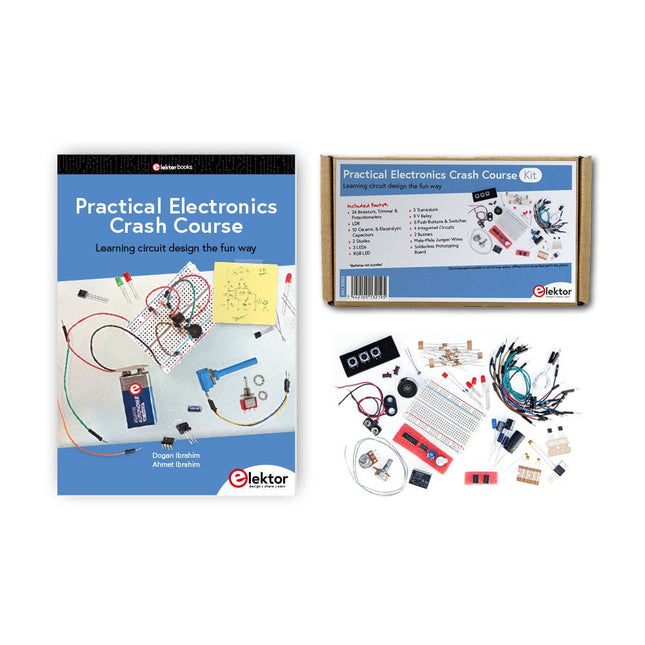
Elektor Bundles Practical Electronics Crash Course (Bundle)
Getting started in electronics is not as difficult as you may think. With this bundle (book + kit of parts), you can explore and learn the most important electrical and electronics engineering concepts in a fun way by doing various experiments. You will learn electronics practically without getting into complex technical jargon and long calculations. As a result, you will be creating your own projects soon. This kit contains the components required to build most of the detailed examples of the book on a breadboard and try them out for real. The kit can, of course, also be used without the book for building other circuits and doing your own experiments. Kit contents 1x 39 Ω, 1 W resistor 1x 47 Ω resistor 1x 180 Ω resistor 1x 330 Ω resistor 3x 1 kΩ resistor 1x 2.2 kΩ resistor 1x 3.9 kΩ resistor 1x 6.8 kΩ resistor 1x 10 kΩ resistor 1x 15 kΩ resistor 1x 22 kΩ resistor 1x 33 kΩ resistor 1x 47 kΩ resistor 1x 56 kΩ resistor 1x 82 kΩ resistor 1x 120 kΩ resistor 1x 680 kΩ resistor 2x 100 kΩ resistor 1x 10 kΩ trimmer 1x 10 kΩ linear potentiometer 1x 100 kΩ linear potentiometer 1x LDR 1x 1 nF ceramic capacitor 2x 10 nF ceramic capacitor 1x 100 nF ceramic capacitor 1x 1 µF, 25 V aluminium electrolytic capacitor 2x 10 µF, 25 V aluminium electrolytic capacitor 1x 100 µF, 25 V aluminium electrolytic capacitor 1x 470 µF, 25 V aluminium electrolytic capacitor 1x 1000 µF, 25 V aluminium electrolytic capacitor 1x RGB LED, Common-Cathode (CC) 1x 1N4148 small signal diode 1x 1N4733A 5.1 V, 1 W Zener diode 3x LED, red 2x BC337 NPN transistor 1x IRFZ44N N-channel MOSFET 2x NE555 timer 1x LM393 comparator 1x 74HCT08 quad AND gate 3x Tactile switch 2x SPDT switch 1x Relay, SPDT, 9 VDC 1x Active buzzer 1x Passive buzzer 50 cm Solid wire, 16 AWG, unjacketed 2x PP3 9 V battery clip 1x Breadboard 20x Jumper wire This bundle contains: Practical Electronics Crash Course Kit (valued at: €45) Book: Practical Electronics Crash Course (normal price: €45)
€ 89,95€ 69,95Best Price
-

Elektor Publishing Elektronenröhren in der Praxis
Grundlagen, Schaltungen und sichere Anwendungen für Einsteiger und Fortgeschrittene Elektronenröhren üben bis heute eine besondere Faszination aus. Ihre langlebige Funktion, ihre Robustheit und ihr charakteristisches Verhalten unterscheiden sie grundlegend von moderner Halbleitertechnik. Trotz ihres Alters sind Röhren keineswegs nur historische Bauteile, sondern finden auch heute noch Anwendung in Audiotechnik, Messtechnik und vor allem im Hobbybereich. Dieses Buch richtet sich an Elektronikinteressierte und Bastler, die Elektronenröhren nicht nur in der Theorie kennenlernen und verstehen, sondern auch in der Praxis einsetzen möchten. Es vermittelt die Grundlagen der Röhrentechnik, erklärt die unterschiedlichen Bauformen und Bezeichnungen, zeigt typische Schaltungen und geht außerdem auf Spannungsversorgung und Netzteile sowie auf Messungen und sicherheitsrelevante Aspekte ein. Der Schwerpunkt liegt auf praxisnahen Erklärungen und realistischen Beispielen aus der Werkstatt. Zahlreiche Hinweise helfen, typische Fehler zu vermeiden, Schaltungen aufzubauen und Röhrengeräte sowie deren Aufbau zu verstehen. Grundkenntnisse der Elektronik werden vorausgesetzt. „Elektronenröhren in der Praxis“ bietet einen verständlichen und fundierten Einstieg in die Röhrentechnik – sachlich, nachvollziehbar und mit klarem Fokus auf die praktische Anwendung.
€ 34,80
Best Price
-

FNIRSI FNIRSI HRM-10 Battery Internal Resistance & Voltage Tester
The FNIRSI HRM-10 is a portable, high-precision battery internal resistance and voltage tester. This device offers true four-wire measurement and is designed for both accuracy and ease of use. It automatically measures internal resistance and voltage values simultaneously, displaying the results on its HD color screen. Users have the option to manually adjust voltage and resistance ranges to suit their needs. The device also includes a sorting mode that automatically filters the good and bad batteries based on user-set thresholds. Additionally, it supports the storage of historical data and allows for exporting measurement records in table format. Features High Measurement Accuracy Tabular Data Export Auto-Evaluate Measurement Results 8 Threshold Settings HD Color Screen Folding Stand 1000 mAh Lithium Battery Specifications Voltage Resistance Measuring range 0-100 V (DC) 0-200 Ω Accuracy ±0.5% ±0.5% Gear Automatic, 1 V, 10 V, 100 V Automatic, 20 mΩ, 200 mΩ, 2 Ω, 20 Ω, 200 Ω Instrument test signal frequency 1 Khz (AC) Rechargeable USB-C (5 V/1 A) Built-in battery 1000 mAh lithium battery User calibration Yes Sorting mode Yes History record Yes Recorded data export Yes Working environment –10°C to +45°C, relative humidity <80% Storage environment –20°C to +80°C, relative humidity <80% Dimensions 158.7 x 80.5 x 28.4 mm Weight 225 g Included 1x FNIRSI HRM-10 Internal Resistance Tester 1x Clip Test Line 1x USB-C data cable 1x Manual Downloads Manual Firmware V0.3
€ 49,95
-
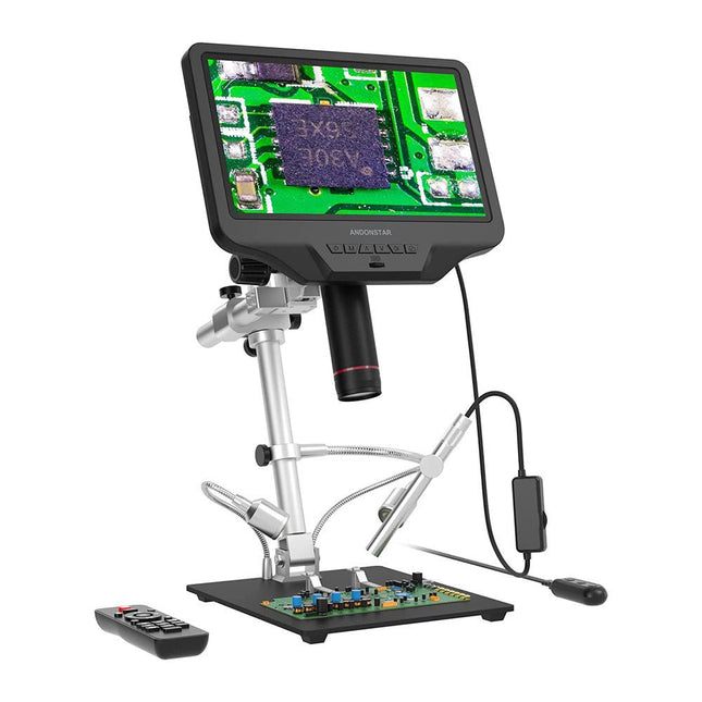
Andonstar Andonstar AD409 Pro-ES 10.1" HDMI Digital Microscope (incl. Endoscope)
The Andonstar AD409 Pro-ES is a digital microscope with an extra-high stand that is also equipped with an endoscope. The microscope allows clear observation of the sides of components, the inside of pipes, etc., enabling 360° observation without dead angles. The microscope also has a remote control that allows you to easily switch between the following image modes: two-lens, microscope and endoscope. Features High-quality metal lens and focusing barrel Professional HDMI digital microscope supports multiple output methods Soldering Microscope with Pro Metal Stand Unique UV filter design 8 Levels adjustable LED Lights Convenient Wireless Remote Control Professional Measurement Software Specifications Screen size 10.1 inch (25.7 cm) Image sensor 4 MP Video output UHD 2880x2160 (24fps)FHD 1920x1080 (60fps/30fps)HD 1280x720 (120fps) Video format MP4 Magnification Up to 300 times (27 inch HDMI monitor) Photo resolution Max. 12 MP (4032x3024) Photo format JPG Focus range Min. 5 cm Frame Rate Max. 120fps Video interface HDMI Storage microSD card (up to 64 GB) PC support Windows, PC software with measurement Mobile phone, tablet terminal support Support WiFi connection and measurement Power source 5 V DC Light source 2 LEDs with the stand Endoscope Yes Stand size 18 x 20 x 32 cm Included 1x Andonstar AD409 Pro-ES Digital Microscope 1x Endoscope 1x Metal stand with 2 LEDs 1x UV filter (already assembled in the lens) 1x IR remote 1x Switch cable 1x Power adapter 1x Wrench 2x Metal clips 1x HDMI cable 1x User manual Downloads Manual Software
€ 339,00€ 289,00Best Price
-
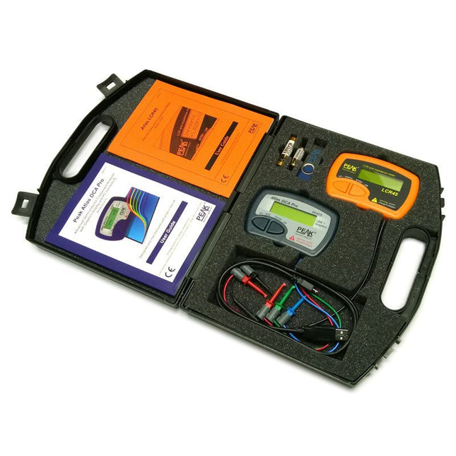
Peak Peak Atlas Pro Pack (LCR45 & DCA75)
This pack contains the LCR45 Passive Component Impedance Meter, great for advanced hobbyists and professionals. It also contains the very popular DCA Pro (model DCA75), fantastic for component identification, pinout identification, detailed characteristic measurement and curve tracing on a PC. Complete with USB cable and software on a USB flash drive. DCA75 Building on the continued success of Peak's existing component identification and analysis instruments, the DCA Pro brings an array of exciting new features for the hobbyist and professional alike. The DCA Pro is an advanced new design that features a graphics display, USB communications, PC Software and an enhanced component identification library. Automatic component type identification Automatic pinout identification (connect any way round) The DCA Pro supports all the components that the popular Peak Atlas DCA55 supports, but adds plenty more. Components supported include: Transistors (including Darlingtons), Silicon and Germanium types. Measures gain, Vbe and leakage MOSFETs, enhancement mode and depletion mode types. Measure on-threshold (at 5 mA) and approx transconductance (for span of 3-5 mA) JFETs, including normally off SiC types. Measures pinch-off voltage (at 1 uA) and approx transconductance (for span of 3-5 mA) IGBTs (insulated gate bipolar transistors). Measures on-threshold (at 5 mA) Diodes and Diode networks LEDs and bicolour LEDs (2 lead and 3 lead types) Zener Diodes with measurement of zener voltage up to 9 V at 5 mA Voltage regulators (measures regulation voltage, drop-out voltage, quiescent current) Triacs and Thyristors that require less than 10 mA of gate current and holding current Stand-alone or with a PC The instrument can be used stand-alone or connected to a PC. Either way, the DCA Pro will automatically identify the component type, identify the pinout and also measure a range of component parameters such as transistor gain, leakage, MOSFET and IGBT threshold voltages, pn characteristics and much more. Curve Tracing When connected to a PC using the supplied USB cable, a range of low current curve-tracing functions can be performed. Various graph types are available, with more to follow: Bipolar transistor output characteristics, IC vs VCE Bipolar transistor gain characteristics, HFE vs VCE Bipolar transistor gain characteristics, HFE vs IC MOSFET and IGBT output function, ID vs VDS MOSFET and IGBT transfer function, ID vs VGS JFET output function, ID vs VDS JFET transfer function, ID vs VGS Voltage regulator, VOUT vs VIN Voltage regulator, IQ vs VIN. PN junction I/V curves, forward and reverse options (for Zener diodes) Curve tracing is performed using test parameters in the range of +/-12 V or +/-12 mA. All curve-tracing data can be instantly pasted into Excel for further graphing and analysis. PC Software is included with the DCA Pro on a Peak USB memory stick. Software designed for Windows 7 and higher (all 32 or 64 bit). LCR45 A great handheld LCR analyzer that can measure the value of your passive component (inductor, capacitor or resistor) and also measure the detailed impedance in a number of modes. The LCR45 offers enhanced measurement resolution (better than 0.1 uH!) whilst also giving you continuous fluid measurements. Additionally, the test frequencies of DC, 1 kHz, 15 kHz and 200 kHz can be set to automatic or manual modes. Supplied with removable gold plated hook probes, battery and user guide. Compatible with standard 2 mm test connectors. Not designed for in-circuit use. Automatic or manual component type selection: Inductor, Capacitor or Resistor Automatic or manual test frequency selection: DC, 1 kHz, 15 kHz and 200 kHz Inductance from 0.1 uH to 10 H Capacitance from 0.1 pF to 10,000 uF Resistance from 0.1 Ohm to 2 MOhm Inductance measurement also shows DC winding resistance Display of "Component type and values", "Complex Impedance", "Magnitude/Phase" and "Admittance" Test frequency displayed for all measurements Typical accuracy of 1.5% for inductors and capacitors (see spec table for details) Typical accuracy of 1% for resistors Test lead complete with gold plated 2 mm plugs and sockets Supplied with removable gold plated hook probes Included LCR45 DCA75 Extra GP23 Battery Extra AAA cell Dual Carry Case
€ 325,49
-

Elektor Digital Röhren 1 (PDF)
Aus dem Inhalt Lieferbarkeit von Röhren Passive Übeltäter – Einfluss der Kondensatoren auf den Klang Übertragerwissen Theorie der Trioden Der richtige Einsatz von Gleichrichterröhren Line-Vorverstärker mit Klangsteller Vollverstärker mit 2 x 50 W oder 2 x 40 W HiFi-CD-Player mit Playstation 1 CD-Filter Nachlese In dem Artikel "Moderne Triodenendstufe mit der legendären 2A3" ab Seite 66 wurden bei den Platinenabbildungen die Maßangaben nicht abgedruckt. Hier die Maße der Originalgrößen: Netzteilplatine (S. 68) 123 x 80 mm Stabilisierung (S. 69) 70 x 85 mm Hauptplatine (S. 71) 295 x 135 mm
€ 15,90
Members: € 14,31
-

Elektor Digital Theorie und Praxis des Röhrenverstärkers (E-book)
Es ist heute nicht mehr ganz einfach, ein Buch über Röhren zu verfassen, da in den letzten Jahrzehnten viel Wissen über dieses interessante Gebiet verloren gegangen ist. Genau das aber ist einer der Gründe, warum dieses Buch geschrieben wurde. Der Autor hat sich zur Aufgabe gemacht, die für den Einsatz von Röhren im Audiobereich bedeutsamen theoretischen und praktischen Kenntnisse zu bündeln und darzustellen. Der Verfasser stützt sich dabei auf seine eigene und umfassende Erfahrung, die er in den vielen Jahren vor der breiten Einführung von Halbleitern durch intensive Auseinandersetzung mit der Röhrentechnologie gewonnen hat. Selbstverständlich werden in den Schaltungsteilen, die nicht unmittelbar im Signalweg sitzen, die Vorzüge zeitgemäßer, aktiver elektronischer Bauteile wie Transistoren oder ICs gezielt ausgenutzt. Hinzu kommt die bevorzugte Verwendung hochqualitativer, moderner Ringkerntransformatoren. In den ersten Kapiteln dieses Bandes wird auf Produktionsverfahren und die Arbeitsweise von Röhren eingegangen, anschließend werden deren Grundschaltungen ausführlich besprochen. Das gewonnene Wissen erfährt in den folgenden Abschnitten eine theoretische Vertiefung bei der genaueren Betrachtung von Endstufen, Klangregelungen usw. Zudem wurden zwei gesonderte Kapitel aufgenommen, die sich mit Klirrverhalten und Verzerrungen, Rauschen, Mikrofonie und anderen Störgeräuschen befassen. In vier weiteren Kapiteln werden vollständige Verstärker-Entwürfe und die Dimensionierungsberechnungen aller Baugruppen im Einzelnen unter Hinweis auf die zugehörigen theoretischen Überlegungen der vorherigen Kapitel vorgestellt. Dabei wird deutlich, dass Röhrenverstärker physikalischen und mathematischen Gesetzen gehorchen, weit verbreitete Legenden und Mystifizierungen dagegen nichts zur Erhellung der funktionellen Zusammenhänge beitragen. Im Übrigen findet der Leser viele nützliche Hinweise bei der konkreten Umsetzung der jeweiligen Schaltung in ein funktionierendes Gerät und Hilfestellungen für die messtechnische Überprüfung der Resultate.
€ 39,80
Members: € 35,82
-
Elektor Publishing Practical Electronics Crash Course
Learning circuit design the fun way Welcome to the world of electronics! Getting started in electronics is not as difficult as you may think. Using this book, you will explore and learn the most important electrical and electronics engineering concepts in a fun way by doing various experiments and by simulating circuits. It will teach you electronics practically without getting into complex technical jargon and long calculations. As a result, you will be creating your own projects soon. No prior knowledge of electronics is required, only some basic algebra is used in a few simple calculations. Many tested and working projects and simulations are presented to familiarise yourself with the construction of electronic circuits. Circuit simulation is introduced at an early stage to enable you to experiment with circuits easily without breaking anything. You will learn: The concepts of voltage, current, and power AC and DC Basic lamp circuits with switches Passive components: resistors, capacitors & inductors RC & RCL circuits Electromagnetism Loudspeakers, relays, buzzers, and transformers Active components: diodes & LEDs, bipolar transistors & MOSFETs Transistor-based switching circuits Optocoupler circuits Astable & monostable multivibrators Using the 555 timer IC The operational amplifier Digital logic Advanced examples: amplifiers, oscillators, filters, and sensors Test and measurement tools Microcontrollers: Arduino UNO, ESP32, Raspberry Pi Pico, and Raspberry Pi Reading datasheets and best practices for selecting components EMC & EMI and norms & regulations
€ 39,95
Members: € 35,96
-

Elektor 07-08/2026 (DE)
Diese Ausgabe steht allen GOLD- und GREEN-Mitgliedern auf der ElektorMagazine-Website zum Download bereit! Sie sind noch kein Mitglied? Hier klicken! MultiRF-EntwicklungsboardEine Plattform zur Evaluierung drahtloser Protokolle für kurze und lange Reichweiten Elektor wird 65Elektronik im Wandel seit 1961 WLAN-basierte Personenerkennung mit dem ESP32Wenn der Router zum Bewegungsmelder wird Drahtlose WaagenVier kleine Waagen = eine große Waage Walter, das kompakte IoT-ModulESP32-S3-SoC, LTE-M/NB-IoT-5G-Modem und GNSS-Receiver 3- und 4-Draht-RTD-Sensoren konditionierenMit Vollbereichsabgleich und Kabelkompensation Drei in einem: 2-Kanal-Oszilloskop/Generator/MultimeterEin Test des Fnirsi 2D15P electronica Fast Forward 2026 für Start-ups und Industriepartner EcologgingEine modulare IoT-Messstation für Umweltdaten Drahtlos-Anbindung für MedizingeräteImmer am Puls mit Bluetooth LE AudiotronicsBrummunterdrückung Mehr Effizienz in der Landwirtschaft durch KI-Modelle und SensorenSteigerung der landwirtschaftlichen Produktivität OPC UA – ein ÜberblickPlattformunabhängiger Datenaustausch Redox-Meter Instrumentenverstärker für Physik- und Engineering-Experimente Aktive differentielle Audio-FilterFür professionelle Frequenzweichen und mehr Elektor-Community-Tipps zu IoT und Sensoren Telegram-gesteuerter WarmwasserbereiterEine Lösung mit ESP32 und Arduino-Software 2026: Eine KI-OdysseeWas wurde eigentlich aus der Fuzzy-Logik? Projekt 2.0 Alarmsignalinjektor + PowerTools zum Suchen verdeckt verlegter Leitungen
€ 15,90


