Open-Source-Code mit Arduino IDE und PlatformIO
Autonomes Fahren: GPS, Accelerometer, Gyroskop
PS3-Controller
Mikrocontroller wie der Arduino und Einplatinenrechner wie der Raspberry Pi haben sich zu beliebten Komponenten entwickelt. Dritter im Bunde ist der ESP32 der Firma Espressif. Mikrocontroller dieser Baureihe zeichnen sich durch eine Vielzahl implementierter Funktionen aus, die bei einem Arduino konventioneller Prägung mit einem Atmel-AVR-Mikrocontroller erst mit weiterer Hardware möglich sind. Prominentes Beispiel sind hier die WiFi- und Bluetooth-Funktionalitäten. Gegenüber einem Raspberry Pi zeichnen sie sich durch einen deutlich geringeren Preis aus.
Allgemeine Informationen für die Realisierung eines Roboterauto-Projekts mit dem ESP32 sind leicht zu finden. Dabei handelt es sich aber oft nur um Ausführungen zu einem Teilaspekt, ohne inhaltliche oder funktionale Abstimmung. So ist nicht nur die Beschaffung der benötigten Informationen mühselig und zeitaufwändig, sie kann auch außerordentlich fehlerträchtig sein.
Ansatzpunkt dieses Buches ist, diese Lücke zu schließen. Es geht auf verschiedene Möglichkeiten eines Chassis ein, vermittelt nötige Kenntnisse und führt schrittweise von einer einfachen Motorsteuerung zu einem komplexen sensor- und sprachgesteuerten Roboterauto. Hacks rund um GPS und eine PlayStation 3 runden die Sache ab.
Inhalt
Bei der Reihenfolge der Kapitel wurde versucht – beginnend bei der Darstellung von grundlegenden Informationen – über die Lösung einfacher Aufgaben zu etwas anspruchsvolleren Techniken zu führen.
Der Mikrocontroller ESP32
Die Software erstellen
Die Stromversorgung
Rund um die Hardware
Das Chassis
Der Gleichstrommotor
Kabellose Steuerung über WiFi
Mit Sensoren Hindernisse erkennen
Eine eigene Roboterauto-App
Servo und Lichtsensor
GPS
Accelerometer / Gyroskop
PS3-Controller
Roboterauto-App
Hinweis zur Software
Die Dateien haben das Suffix (.cpp). Grund ist die Entwicklung mit PlatformIO. Mit Copy & Paste sollten sie auch in der Arduino-IDE verwendet werden können.
The Siglent SDS1204X-E is a powerful 200 MHz four-channel oscilloscope that is built on the same platform as the very popular SDS1202X-E but with several significant improvements, including two 1 GSa/s ADCs and two 14 Mpt memory modules. Waveform capture rates are up to 100,000 wfms/s in normal mode and 400,000 wfms/s in sequence mode. The SDS1000X-E scopes feature a large 7” 256-level color display with intensity grading and color temperature features.
Specifications
Bandwidth
200 MHz
Sampling Rate (Max.)
1 GSa/s
Channels
2CH+EXT4CH
Memory Depth (Max.)
7 Mpts/CH (not interleave mode); 14 Mpts/CH (interleave mode)
Waveform Capture Rate (Max.)
100,000 wfms/s (normal mode), 400,000 wfms/s (sequence mode)
Trigger Types
Edge, Slope, Pulse width, Window, Runt, Interval, Dropout, Pattern, Video
Serial Trigger (Standard)
I²C, SPI, UART/RS232, CAN, LIN
Decode Type (Standard)
I²C, SPI, UART/RS232, CAN, LIN
16 Digital Channels (four channel series only, option)
Maximum waveform capture rate up to 1 GSa/s, Record length up to 14 Mpts/CH
USB AWG module (four channel series only, option)
One channel, 25 MHz, sample rate of 125 MHz, wave length of 16 kpts
Bode plot ( four channel series only)
Minimum start frequency of 10 Hz, minimum scan bandwith of 500 Hz, maximum scan bandwidth of 120 MHz (dependent on Oscilloscope and AWG bandwidth), 500 maximum scan frequency points
USB WIFI adapter (four channel series only, option)
802.11b/g/b, WPA-PSK, the adapter must be supplied by Siglent to ensure proper functioning
Downloads
Datasheet
Manual
Programming Guide
Elektor GREEN en GOLD leden kunnen deze uitgave hier downloaden.Nog geen lid? Klik hier om een lidmaatschap af te sluiten.
Kiesschijftelefoon als afstandsbedieningvoor licht kies 1; voor koffie kies 2
GPS-gebaseerde snelheidsmeternooit meer bekeuringen
RGB-stroboscoop met Arduinokleurige toepassing van een nuttig instrument
Draadloze nooddrukknopmeer veiligheid met LoRa
Alle begin......volgt de emitter
Vrij te kiezen onafhankelijke hystereseniveaus voor comparatorenmet simulaties, spreadsheets en algebra
Impedantie-analyzer op basis van een ESP32simpel, weinig onderdelen en goedkoop!
Oost West Lab Bestzelfbouw moet gestimuleerd!
Het MCCAB Arduino Nano Training Boardalle hardware voor de “Microcontrollers Hands-On Course”
Uit het leven gegrepenmodern luddisme
Sensor-ABC: de DS18B20 temperatuursensoraansluiting op de 1-Wire bus
Gaan Matter en Thread het Smart Home redden?nieuwe standaarden om het slimme huis te vereenvoudigen
Een kwestie van samenwerkingontwikkelen met het Thing Plus Matter Board en Simplicity Studio
Elektor IIIIinfographicIoT en sensoren
Matter, ExpressLink, Rainmaker – waar hebben we het over?vraaggesprek met Amey Inamdar van Espressif
De juiste keuze van microcontroller-ontwikkelkitsvoor IoT- en IIoT-toepassingen
Condensatoren gedragen zich niet altijd capacitief!
Een NTP-klok met CircuitPythonwaarom zou je deze programmeertaal gebruiken?
Bouw een cool IoT-display'met de Phambili Newt
De doppler-bewegingssensor HB100theorie en praktijk
Een gids voor puristisch programmeren (deel 1)voor STM32 en andere controllers
Siglent SDM3045X-multimeter
Microprocessoren voor embedded systemenvreemde onderdelen
Microcontroller-documentatie verklaarddeel 3: blokschema’s en meer
Low-power LoRa-weerstationbouw zelf een weerstation met een groot bereik
Transverter voor de 70cm-band
Klimaat aan ingenieurssnelheid is geboden!
Hexadoku
De mens is van nature uitgerust met sensoren voor geluid, licht, geur, smaak en gevoel. Zintuigen die met elektronica slechts ten dele gekopieerd kunnen worden. Met de Elektor sensorkit kunnen we wel aardig in de buurt komen.
Sensoren kunnen elektronica aansturen, maar ze kunnen ons ook van informatie voorzien. Daarom vormt niet alleen het meten van grootheden, maar ook het zichtbaar maken ervan via de Arduino seriële monitor een niet onbelangrijk deel van dit boek.
De microprocessor ATtiny85 die de Arduino-taal begrijpt, maakt het experimenteren met sensoren gemakkelijk en goedkoop. We zullen niet snel een Arduino-kaartje vast solderen in een permanente opstelling. Bij een achtpotige ATtiny zal dat geen schuldgevoel opleveren. Dat neemt niet weg dat alle sketches gewoon op elk Arduino-board draaien met mogelijk hier en daar een aanpassing van pennummers omdat die kunnen verschillen met reguliere Arduino-boards.
We zullen uitgebreid aandacht besteden aan het programmeren van de ATtiny. Veel schakelingen zijn bruikbaar in het natuurkundepracticum op school of voor bedrijfsmatige toepassingen. Maar de nadruk ligt toch wel op de (beginnende) elektronicahobbyist die zijn vrije tijd op een leuke maar vooral ook nuttige manier wil besteden. Want meer dan ooit tevoren heeft techniek de toekomst.
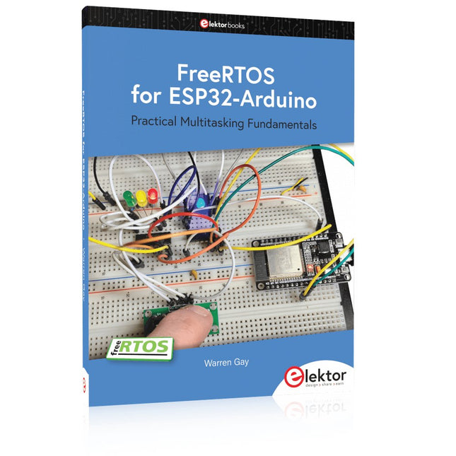
Practical Multitasking Fundamentals
Programming embedded systems is difficult because of resource constraints and limited debugging facilities. Why develop your own Real-Time Operating System (RTOS) as well as your application when the proven FreeRTOS software is freely available? Why not start with a validated foundation?
Every software developer knows that you must divide a difficult problem into smaller ones to conquer it. Using separate preemptive tasks and FreeRTOS communication mechanisms, a clean separation of functions is achieved within the entire application. This results in safe and maintainable designs.
Practicing engineers and students alike can use this book and the ESP32 Arduino environment to wade into FreeRTOS concepts at a comfortable pace. The well-organized text enables you to master each concept before starting the next chapter. Practical breadboard experiments and schematics are included to bring the lessons home. Experience is the best teacher.
Each chapter includes exercises to test your knowledge. The coverage of the FreeRTOS Application Programming Interface (API) is complete for the ESP32 Arduino environment. You can apply what you learn to other FreeRTOS environments, including Espressif’s ESP-IDF. The source code is available from GitHub. All of these resources put you in the driver’s seat when it is time to develop your next uber-cool ESP32 project.
What you will learn:
How preemptive scheduling works within FreeRTOS
The Arduino startup “loopTask”
Message queues
FreeRTOS timers and the IDLE task
The semaphore, mutex, and their differences
The mailbox and its application
Real-time task priorities and its effect
Interrupt interaction and use with FreeRTOS
Queue sets
Notifying tasks with events
Event groups
Critical sections
Task local storage
The gatekeeper task
The Piccolino rapid development board can be used to design microcontroller circuits quickly. The Piccolino has a fast 16f887 PIC microcontroller, voltage regulator, and communications module, and can be easily extended using its four headers.
This e-book contains 30 projects based on the Piccolino. We'll use its unique communications facilities and get the Piccolino to communicate with programs on a PC. On the PC, we use the free programming language Small Basic. You can use this to create Windows programs with buttons and graphs quickly. You will learn how to analyze components such as inductors, capacitors, and OPAMPs, and how to display the measurement results in a graphical format. This will help you to design your circuits easily.
We will then start to adapt to the Piccolino. We'll add components to it to make it more powerful, with extra features such as flow control and digital to analog conversion. The clear instructions will enable you to design and build your adaptations. This way you can make your custom designed Piccolino.
We'll end up making an extension: a PCB that that can be mounted on the Piccolino headers. As an example, we'll design and build an extension for an LCD. You can use the included board layout to make your PCB or have it made for you. At the same time, you will learn how to make your extensions. The only limitation is your imagination!
The clear descriptions along with circuit diagrams and photos, will make the building of these projects an enjoyable experience. Each project has a clear explanation of the reasons why it was designed in a particular way. This helps you learn a lot about the Piccolino, as well as Small Basic, and the components that are used in this e-book. You can adapt the projects to suit your requirements or combine several projects.
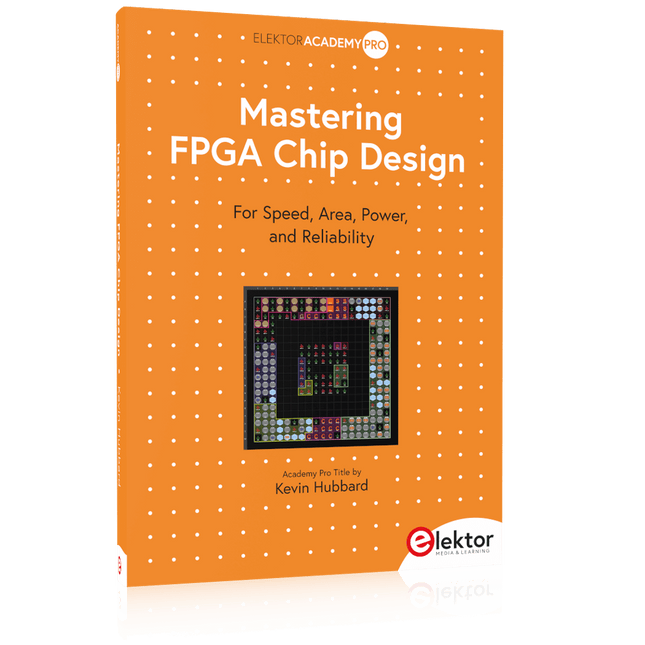
For Speed, Area, Power, and Reliability
This book teaches the fundamentals of FPGA operation, covering basic CMOS transistor theory to designing digital FPGA chips using LUTs, flip-flops, and embedded memories. Ideal for electrical engineers aiming to design large digital chips using FPGA technology.
Discover:
The inner workings of FPGA architecture and functionality.
Hardware Description Languages (HDL) like Verilog and VHDL.
The EDA tool flow for converting HDL source into a functional FPGA chip design.
Insider tips for reliable, low power, and high performance FPGA designs.
Example designs include:
Computer-to-FPGA UART serial communication.
An open-source Sump3 logic analyzer implementation.
A fully functional graphics controller.
What you need:
Digilent BASYS3 or similar FPGA eval board with an AMD/Xilinx FPGA.
Vivado EDA tool suite (available for download from AMD website free of charge).
Project source files available from author’s GitHub site.
High-Performance LoRa Communication Device
The Elecrow ThinkNode M5 is a compact, portable LoRa communication device designed for off-grid messaging, location sharing, and outdoor use. Powered by an ESP32-S3 processor and an SX1262 LoRa chip, it comes pre-installed with Meshtastic firmware and can be configured conveniently via Bluetooth using the official Meshtastic app.
The integrated multi-GNSS module supports GPS, GLONASS, BeiDou, and QZSS for reliable positioning and location sharing. Messages and device information are displayed on the energy-efficient 1.54-inch e-paper screen, while the built-in 1,200 mAh rechargeable battery enables extended mobile operation.
With its integrated LoRa antenna, compact housing, RTC, and support for both Meshtastic and MeshCore firmware, the ThinkNode M5 is a practical communication solution for hiking, camping, remote locations, and emergency situations where conventional mobile networks are unavailable.
Features
LoRa communication
Multi-GNSS positioning
1,200 mAh rechargeable battery
1.54-inch e-paper display
Built-in RTC
Compatible with MeshCore
Compatible with Meshtastic
Specifications
Main Processor (ESP32-S3)
CPU/SoC
Xtensa 32-bit LX7 dual-core processor, clocked at up to 240 MHz
System Memory
512 KB SRAM, 8 MB PSRAM
Storage
4 MB Flash, 384 KB ROM
Firmware
Meshtastic firmware is fully compatible, and the signal is transmitted in LoRa mode
EPD (Electronic Paper Display)
Display Size
1.54 inch EPD (monochrome Ink screen)
Display Materials
E-lnk (Electronic Ink)
Resolution
200 x 200
Driver Chip
SSD1681 (via SPI or I²C interface)
Global Fresh Time
2s
Wireless Communication
Bluetooth
Bluetooth Low Energy and Bluetooth 5.0 (phone configuration)
LoRa
SX1262 LoRa Module, EU 868 MHz(external antenna)
Hardware
Interfaces
USB-C, RP-SMA
Function
GPS Location (GPS, GLONASS, BeiDou, QZSS), EPD Display, RTC, USB 2.0, PMU power management (built-in 1200 mAh lithium battery), buzzer, etc.
Button
Knob Switch, Function Button, Page Turn Button, GPS Switch, Reset Button
LED Indicator
Power supply, GPS/LoRa indication
Others
Power Input
5 V/1 A, supports USB or lithium battery power supply
Power consumption
The maximum working current is about 340 mA (CPU + LoRa module), and the low power consumption is about 34 uA
Operating Temperature
-10~50°C
Storage Temperature
-20~60°C
Relative humidity
10-95%, @ 40°C (non-condensing)
Enclosure
ABS Plastic
Dimensions
82 x 51.6 x 26.3 mm
Weight
81 g
Included
1x Elecrow ThinkNode M5
1x LoRa antenna
1x USB-C cable
1x Manual
Downloads
Manual
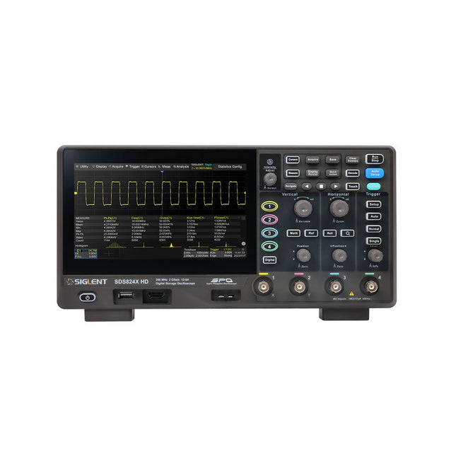
The Siglent SDS814X HD digital storage oscilloscope is based on 2 GSa/s, 12-bit Analog-Digital Converters and front ends with excellent noise floor performance. With a 100 MHz bandwidth, and a maximum record length of 50 Mpts, and the capability to analyze 4 analog channels alongside 16 digital channels, the SDS814X HD is perfectly suited for mixed signal analysis.
Features
12-bit High Resolution
12-bit Analog-Digital Convertors with sample rate up to 2 GSa/s
Front ends with 70 μVrms noise floor @ 100 MHz bandwidth
2/4 analog channels, up to 700 MHz bandwidth
SPO technology
Waveform capture rate up to 80,000 wfm/s (normal mode), and 500,000 wfm/s (sequence mode)
Supports 256-level intensity grading and color temperature display modes.
Up to 50 Mpts record length
Digital trigger system
Intelligent trigger: Edge, Slope, Pulse width, Window, Runt, Interval, Dropout, Pattern, Video (HDTV supported), Qualified, Nth edge, Delay, Setup/Hold time.
Serial bus triggering and decoder, supports protocols I²C, SPI, UART, CAN, LIN.
Segmented acquisition (Sequence) mode, dividing the maximum record length into multiple segments (up to 80,000), according to trigger conditions set by the user, with a very small dead time between segments to capture the qualifying event.
History waveform record (History) function, the maximum recorded waveform length is 80,000 frames.
Automatic measurements on 50+ parameters, supports statistics with histogram, track, trend, Gating measurement, and measurements on Math, History and Ref.
4 Math traces (2 Mpts FFT, addition, subtraction, multiplication, division, integration, differential, square root, etc.), supports formula editor.
Abundant data analysis functions such as Search, Navigate, Counter, Bode plot and Power Analysis
High Speed hardware-based Mask Test function, with Mask Editor tool for creating user-defined masks
16 digital channels (optional)
25 MHz waveform generator (optional)
7" TFT-LCD display with 1024 x 600 resolution; Capacitive touch screen supports multi-touch gestures.
Interfaces include: USB Hosts, USB Device (USBTMC), LAN (VXI-11/Telnet/Socket), Pass/Fail, Trigger Out
Built-in web server supports remote control over the LAN port using a web browser. Supports SCPI remote control commands. Supports external mouse and keyboard. Supports NTP.
Specifications
Analog Channels
4
Bandwidth
100 MHz
Vertical resolution
12-bit
Sample rate (Max.)
One channel mode: 2 GSa/sTwo channel mode: 1 GSa/sFour channel mode: 500 MSa/s
Memory depth (Max.)
One channel mode: 50 Mpts/chTwo channel mode: 25 Mpts/chFour channel mode: 10Mpts/ch
Waveform capture rate (Max.)
Normal mode: 80,000 wfm/sSequence mode: 500,000 wfm/s
Trigger type
Edge, Slope, Pulse width, Window, Runt, Interval, Dropout, Pattern, Video, Qualified, Nth edge, Delay, Setup/Hold time, Serial
Serial trigger and decode (Standard)
I²C, SPI, UART, CAN, LIN
Measurement
50+ parameters, statistics, histogram, trend, and track supported
Math
4 traces 2 Mpts FFT, Filter, +, -, x, ÷, ∫dt, d/dt, √, Identity, Negation, Absolute, Sign, ex, 10x, ln, lg, Interpolation, MaxHold, MinHold, ERES, Average. Supports formula editor
Data analysis
Search, Navigate, History, Mask Test, Counter, Bode plot, and Power Analysis
Digital channel (optional)
16-channel; maximum sample rate up to 1 GSa/s; record length up to 10 Mpts
USB AWG module (option)
One channel, 25 MHz, sample rate of 125 MHz, wave length of 16 kpts, isolated output
I/O
2x USB 2.0 Host, USB 2.0 Device, 10/100 M LAN, Auxiliary output (TRIG OUT, PASS/FAIL), SBUS (Siglent MSO)
Probe (Standard)
Passive probe PB470 for each channel
Display
7 TFT-LCD with capacitive touch screen (1024x600)
Included
1x Siglent SDS814X Oscilloscope
4x Passive probe (100 MHz) PP510
1x Power cord (EU)
1x USB cable
1x Certificate of calibration
1x Quick start
Downloads
Datasheet
Manual
Programming guide
The FNIRSI SG-003A multi-functional Signal Generator a.k.a. Process Meter/Calibrator is a high-precision voltage/current generator and meter. The SG-003A provides highly accurate reference voltages or currents for testing and calibrating other measurement instruments like multimeters and oscilloscopes.
Besides voltages and currents, the SG-003A also generates rectangular pulse signals with precisely programmable frequencies and duty cycles. Its converter mode turns the SG-003A into a precision voltage-controlled current source, or current-controlled voltage source, and even a voltage- or current-controlled frequency generator.
The SG-003A is a great tool for checking your multimeter’s accuracy and precision, and for testing e.g. LEDs.
Features
Accuracy (voltage/current)
0.1% ±0.005
Resolution (current)
0.01 mA
Frequency
0-10 kHz
Resolution
5 digits
Output power
24 V
Display
2.4" TFT LCD (320 x 240)
Dimensions
92 x 72 x 30 mm
Weight
165 g
Specifications
Signal
Range
Precision
Resolution
Max load
External power supply
Active current output
0~24 mA
±(0.1% + 0.005)
0.01 mA
750 Ω
Passive current output (XMT)
0~24 mA
±(0.1% + 0.005)
0.01 mA
0~30 V
Voltage output
0~24 V
±(0.1% + 0.005)
0.01 V
24 V loop
0~24 mA
±(0.1% + 0.005)
0.01 mA
Frequency output
0~9999 Hz
±2%
5 digits
Current input
0~24 mA
±(0.1% + 0.005)
0.01 mA
Voltage input
0~30 V
±(0.1% + 0.005)
0.01 V
Included
1x FNIRSI SG-003A Signal generator
4x Test clips
1x USB charger
1x USB-C cable
1x Manual
Downloads
Manual
Firmware V4.3
Praktische Anwendungen und Projekte mit Arduino, ESP32 und RP2040
Tauchen Sie ein in die faszinierende Welt der Regelungstechnik mit Arduino und ESP32! Dieses Buch bietet Ihnen einen praxisnahen Einstieg in die klassischen und modernen Methoden der Regelung, darunter PID-Regler, Fuzzy-Logik und Sliding-Mode-Regler.
Im ersten Teil lernen Sie die Grundlagen der beliebten Arduino-Controller, wie den Arduino Uno und den ESP32, sowie die Integration von Sensoren für Temperatur- und pH-Messung (NTC, PT100, PT1000, pH-Sensor). Sie erfahren, wie diese Sensoren in verschiedenen Projekten eingesetzt werden und wie Sie Daten auf einem Nextion TFT-Display visualisieren.
Weiter geht es mit der Einführung in Stellglieder wie MOSFET-Schalter, H-Brücken und Solid-State-Relais, die zur Steuerung von Motoren und Aktoren verwendet werden. Sie lernen, Regelstrecken zu analysieren und zu modellieren, einschließlich PT1- und PT2-Regelungen.
Der Schwerpunkt des Buches liegt auf der Implementierung von Fuzzy- und PID-Reglern zur Regelung von Temperatur und DC-Motoren. Dabei werden sowohl der Arduino Uno als auch der ESP32 eingesetzt. Zudem wird der Sliding-Mode-Regler vorgestellt.
Im vorletzten Kapitel erkunden Sie die Grundlagen neuronaler Netze und lernen, wie maschinelles Lernen auf einem Arduino eingesetzt werden kann. Im letzten Kapitel gibt es noch ein praktisches Beispiel für einen Fuzzy-Regler zur Stromeinspeisung ins Hausnetz.
Dieses Buch ist die perfekte Wahl für Ingenieure, Studierende und Elektroniker, die ihre Projekte mit innovativen Regelungstechniken erweitern möchten.
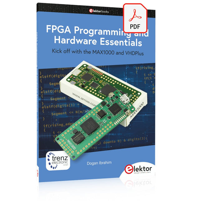
Kick off with the MAX1000 and VHDPlus
Ready to Master FPGA Programming? In this guide, we’re diving into the world of Field Programmable Gate Arrays (FPGAs) – a configurable integrated circuit that can be programmed after manufacturing. Imagine bringing your ideas to life, from simple projects to complete microcontroller systems!
Meet the MAX1000: a compact and budget-friendly FPGA development board packed with features like memory, user LEDs, push-buttons, and flexible I/O ports. It’s the ideal starting point for anyone wanting to learn about FPGAs and Hardware Description Languages (HDLs).
In this book, you’ll get hands-on with the VHDPlus programming language – a simpler version of VHDL. We’ll work on practical projects using the MAX1000, helping you gain the skills and confidence to unleash your creativity.
Get ready for an exciting journey! You’ll explore a variety of projects that highlight the true power of FPGAs. Let’s turn your ideas into reality and embark on your FPGA adventure – your journey starts now!
Exciting Projects You’ll Find in This Book
Arduino-Driven BCD to 7-Segment Display Decoder
Use an Arduino Uno R4 to supply BCD data to the decoder, counting from 0 to 9 with a one-second delay
Multiplexed 4-Digit Event Counter
Create an event counter that displays the total count on a 4-digit display, incrementing with each button press
PWM Waveform with Fixed Duty Cycle
Generate a PWM waveform at 1 kHz with a fixed duty cycle of 50%
Ultrasonic Distance Measurement
Measure distances using an ultrasonic sensor, displaying the results on a 4-digit 7-segment LED
Electronic Lock
Build a simple electronic lock using combinational logic gates with push buttons and an LED output
Temperature Sensor
Monitor ambient temperature with a TMP36 sensor and display the readings on a 7-segment LED
Downloads
Software