
Search results for "Raspberry pi debug probe"
-

Elektor Digital PIC Cookbook for Virtual Instrumentation (E-book)
The software simulation of gauges, control-knobs, meters and indicators which behave just like real hardware components on a PC’s screen is known as virtual instrumentation. In this book, the Delphi program is used to create these mimics and PIC based external sensors are connected via a USB/RS232 converter communication link to a PC. Detailed case studies in this Book include a virtual compass displayed on the PC’s screen, a virtual digital storage oscilloscope, virtual -50 to +125 degree C thermometer, and FFT sound analyser, a joystick mouse and many examples detailing virtual instrumentation Delphi components. Arizona’s embedded microcontrollers – the PIC's are used in the projects and include PIC16F84A, PIC16C71, DSPIC30F6012A, PIC16F877, PIC12F629 and the PIC16F887. Much use is made of Microchip’s 44 pin development board (a virtual instrument ‘engine)’, equipped with a PIC16F887 with an onboard potentiometer in conjunction with the PIC’s ADC to simulate the generation of a variable voltage from a sensor/transducer, a UART to enable PC RS232 communications and a bank of 8 LED's to monitor received data is also equipped with an ISP connector to which the ‘PICKIT 2’ programmer may easily be connected. Full source code examples are provided both for several different PIC’s, both in assembler and C, together with the Pascal code for the Delphi programs which use different 3rd party Delphi virtual components.
€ 19,95
Members: € 17,96
-
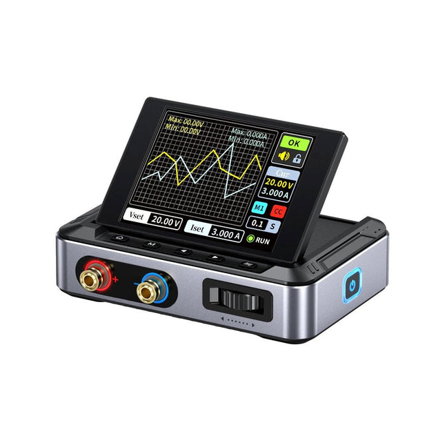
FNIRSI FNIRSI DPS150PD DC Power Supply (150 W)
The FNIRSI DPS150 is a high-performance adjustable DC power supply that features a USB-C input interface and multiple power supply modes, allowing precise adjustment of output voltage (0-30 V) and current (0-5 A). It provides efficient, low-consumption, and stable output, equipped with multiple safety protection functions including overvoltage, overcurrent, overload, overheating, and reverse connection. It can be flexibly applied to serial connection of multiple devices, with rich and user-friendly display and operation, compact and portable design, meeting various application needs. Features 30 V, 5 A, 150 W variable DC power with 0.01 V, 0.001 A precision, CC/CV modes, and <20 mV ripple to protect sensitive electronics. Supports PC, QC, and DC inputs with programmable outputs and 6 preset voltage/current settings. Compatible with 4 mm banana plugs, U-shaped terminals, and copper wires for various equipment. 8 safety mechanisms including overvoltage, current, short circuit, and overheating protection. 2.8-inch HD IPS screen with 90° flip, numerical and curve displays for easy monitoring. Small, space-saving design for use in labs, repairs, and DIY projects. Specifications Input Voltage 5~32 V DC Input Current 100 mA-5 A Output Voltage 0-30 V Output Current 0~5 A Output Power 0-150 W Input Way PD fast charger QC fast charger Power bank DC power adapters Operating Environment 0-40°C Load Regulation 0.49% Full Load Efficiency 96.30% Display 2.8 inch (320 x 240) Dimensions 106 x 76 x 28 mm Weight 178 g Included 1x DPS150 Power Supply 2x Alligator clip wires (black & red) 1x C2C PD charging cable 1x 100 W PD GaN Adapter (EU) 1x Micro USB cable 1x Manual Downloads Manual Firmware V0.0.1
€ 95,00
-

OWON OWON VDS1022I 2-ch USB Oscilloscope (25 MHz)
OWON VDS1022I 2-channel USB oscilloscope (25 MHz) is a oscilloscope for use with a computer. It is powered by USB and has a small size, making it easy to take it with you. The oscilloscope is very economical. It has a shielded USB connection, reducing interference and protecting the computer against over-voltage. The multi port on the scope can be used for external triggering, trigger out or Pass / Fail output. Features 25 MHz bandwidth, and max 1 GS/s real-time sample rate 10M record length Friendly UI: FFT, or X-Y, and waveform 2 views displayed on the same screen Multi-trigger option: edge, video, slope, pulse, and alternate USB isolation – less signal inference, more PC protection USB bus powering, and LAN remote control (optional) Ultra-thin body design, easy portability Specifications Bandwidth 25 MHz Channel 2+1 (multi) Sample Rate 100 MSa/s Horizontal Scale (s/div) 5 ns/div~100s/div, step by 1~2~5 Record Length 5K Max Input Voltage 400 V (PK - PK) (DC+AC, PK - PK) 40 V (PK - PK) (DC+AC, PK - PK) Vertical Resolution (A/D) 8 bits (2 channels simultaneously) Model VDS1022I Vertical Sensitivity 5 mV/div~5 V/div Trigger Type Edge, Pulse, Video, Slope, and Alternate Trigger Mode Auto, Normal, and Single Acquisition Mode Sample, Peak Detect, and Average Waveform Math +, -, ×, ÷, invert, FFT Communication Interface USB 2.0 (isolation) Multi-function Interface Signal Type Level Standard TTL Power Supply 5.0 V/1 A Power Consumption ≤2.5 W Dimensions (W × H × D) 170 x 120 x 18 mm Weight 0.26 kg Included 1x OWON VDS1022I oscilloscope 1x CD-ROM 1x Quick start guide 2x Oscilloscope probe 1x Probe tool 1x Power adapter 1x USB cable 1x Silicone case protectors 1x Power cable Downloads Datasheet User manual SCPI protocol USB driver
€ 119,00
-

Elektor Digital Édition spéciale : Shields pour Arduino (PDF)
Concrétisez vos rêves, réalisez les projets les plus fous : un odomètre pour la roue de votre hamster, la surveillance complètement automatisée de votre fourmilière avec interface web, ou le Sandwich-O-Mat ? une machine qui grille les sandwichs de votre choix. Avec les cartes Arduino et le mouvement DIY (« fais-le toi-même ») ou maker, se mettre à programmer des microcontrôleurs est devenu un jeu d?enfant. Une deuxième révolution a eu lieu : des développeurs ingénieux ont mis sur le marché de petites cartes ? appelées « shields » ou modules ? qui simplifient considérablement l?utilisation d?autres dispositifs. Ces petits modules contiennent tous les composants électroniques nécessaires pour la connexion au microcontrôleur ; quelques fils avec des fiches suffisent pour le raccordement, ce qui évite d?avoir à câbler et fait gagner du temps. En outre, il est également possible de manipuler de minuscules composants dépourvus de pattes de connexion (ceux de type CMS). Projets Arduino et le monde extérieur Capteur BMP180, introduction aux bibliothèques et à l?I²C Initiation aux entrées/sorties avec un shield polyvalent Adaptateur I²C pour LCD et afficheurs à matrice de points Shield clavier & LCD Convertisseur de niveau W5100 : connexion à internet Shields d?extension des entrées/sorties Relais et relais statiques Shield multifonction : unité de commande universelle Connexion d?un lecteur de carte SD par SPI Touches et afficheurs à 7 segments Convertisseur analogique/numérique à 16 bits Convertisseur numérique/analogique MCP4725 Pilote de servomoteurs à 16 voies PWM Lecteur MP3 Enregistreur de données GPS avec stockage sur carte SD Capteur tactile Joystick SHT31 : température et humidité Capteur d?UV-A VEML6070 Temps de vol VL53L0X Mesure de distance à ultrasons Afficheur matriciel à LED à base de MAX7219 Horloge en temps réel DS3231 Circuit d?extension de port MCP23017 Communication radio à 433 MHz Gyroscope MPU-6050 Accéléromètre ADXL345 LED RVB WS2812 Cartes d?alimentation Capteurs de gaz MQ-xx Capteur de dioxyde de carbone (CO2) Capteur de courant ACS712 Capteur de courant INA219 Pilote de moteur L298 Kit RFID MFRC522 Moteur pas à pas 28BYJ-48 Carte avec pilote de moteur ultra-silencieux TMC2209 Potentiomètre numérique X9C10x Écran couleur TFT avec contrôleur/pilote ST7735 Écran à encre électronique Module Bluetooth Compteur Geiger Module GSM SIM800L Multiplexeur I²C Module CAN (Controller Area Network)
€ 10,95
Members: € 9,86
-

Elektor Digital Experimenting with Red Pitaya STEMlab Gen 2 (E-book)
Practical Projects and Programs With Experimenting with Red Pitaya STEMlab Gen 2, Red Pitaya goes beyond a versatile board. It becomes a powerful laboratory instrument for precision measurement, analysis, and control. From the fundamentals of electronic project development, monitoring, control, and design to testing, this book walks you step-by-step through everything you need to know to harness the full potential of Red Pitaya hardware and software. The book presents real-time, FPGA-based projects that are developed on a PC using the Vivado environment, then transferred to the Red Pitaya for execution and testing. You will learn about enhanced performance, expanded I/O capabilities, improved FPGA features, and advanced connectivity options that open up new frontiers for precision measurement, monitoring, and control in your embedded applications. Inside the book you will discover: A deep dive into Red Pitaya architecture and hardware design Electronic experiments using Red Pitaya for measurement and monitoring Hands-on projects using the Python programming language Practical guidance for FPGA programming using Red Pitaya Red Pitaya FPGA projects using the Verilog HDL under Vivado IDE Practical design of electronic projects including measurement and testing Step-by-step examples that bridge theory and real-world implementation Whether you are designing your own electronic circuits, developing signal analysis tools, or creating real-time control or monitoring systems, this book provides you the knowledge and confidence you need to fully learn and customize the Red Pitaya platform.
€ 32,95
Members: € 29,66
-

OWON OWON ADS914A 4-ch Oscilloscope (125 MHz)
The OWON ADS900A series is a compact 12-bit digital oscilloscope offering up to 2 GSa/s, 100 Mpts memory, and 125/250 MHz bandwidth. With its 7" multi-touch display, FFT, protocol decoding, and integrated logic analyzer, it delivers precise signal analysis for lab, workshop, and field applications. Specifications ADS914A ADS924A Bandwidth (-3 dB) 125 MHz 250 MHz Channels 4 Max. sample rate 2 GSa/s (single-channel) 1 GSa/s (dual-channel) 500 MSa/s (full-channel) DC Gain Accuracy 3% (≤1 mV) 2% (≥2 mV) Max memory depth 100M Vertical resolution 12 bits Relay time accuracy ±25 ppm (typical) Input Impedance 1 MΩ±2%, parallel with20 pF±5 pF Probe Attenuation Coefficient 1.00μX-1M.00X,step by 1-2-5, support custom Trigger type Edge, Video, Pulse, Slope, Runt, Windows, Timeout, Nth, Logic, RS232/UART, I²C, SPI CAN, LIN Bus decoding RS232/UART, I²C, SPI, CAN, LIN Auto measurement Period, Frequency, +Width, -Width, Rise Time, Fall Time, Scr Duty, +Duty,-Duty, Vavg, Vpp, VRMS, Overshoot, Vmax, Vmin, Vtop, CycRms, Vbase, Vamp, Preshoot, Std Dev, +Pulse Cnt, -Pulse Cnt, Rise Cnt, Fall Cnt, Area, Cyc Area, Delay(A↑-B↑), Delay(A↑-B↓), Delay(A↓-B↑), Delay(A↓-B↓), Phase(A↑-B↑) Phase(A↑-B↓), Phase(A↓-B↑), Phase(A↓-B↓), FRR(A↑-B↑), FRF(A↑-B↓) FFR(A↓-B↑), FFF(A↓-B↓), LRR(A↑-B↑), LRF(A↑-B↓), LFR(A↓-B↑), LFF(A↓-B↓) Waveform Math +, -, *, /, &&, ||, ^, !, Intg, Diff, Sqrt, Function operation (Lg / Ln / Exp / Abs / Sine / Cosine / Tan), FFT, FFT rms, User Defined, digital filter (low pass, high pass, band pass, band reject) Frequency counter 6-digit frequency counter Maximum frequency: maximum analog bandwidth of oscilloscope Voltmeter Support DC, AC+DCrms, ACrms, Resolution: 4 digits (ACV/DCV) Logical Analyzer Specifications Number of channels 16 input channels (D0-D15) (D0 to D7, D8 to D15) Max. input voltage ±40V peak CAT I, transient overvoltage 800Vpk Input Impedance 100kΩ, 8 pF Vertical resolution 1 bit Other Communication Interface HDMI, USB device, USB Host, Trig Out (P/F), LAN Display 7 inch (1024x600), capacitive multi-touch screen Power supply interface USB-C Dimensions 260 x 160 x 78 mm Weight 1.5 kg Included 1x OWON ADS914A Oscilloscope 1x Power Adapter 1x Power Cord 1x USB Cable 1x Probe 1x Quick Guide Downloads Manual Quick Guide PC Software
€ 579,59
-

Elektor Digital Fahrzeugdiagnose mit OBD II (PDF)
Ungefähr seit dem Jahr 2000 bieten Fahrzeuge Zugriff auf Diagnosedaten, Messwerte und erkannte Fehler, die mit preiswerten Geräten ausgelesen werden können. Die Daten helfen Ihnen nicht nur bei der Fehlersuche, sondern auch beim Gebrauchtwagenkauf oder dem reibungslosen Bestehen der nächsten Hauptuntersuchung. Die zunehmende Komplexität und Vernetzung der integrierten elektronischen Kontroll- und Steuerungssysteme im Fahrzeug erfordert vom Kfz-Mechatroniker sowie dem ambitionierten Selbstschrauber ein tiefgreifendes Verständnis der Thematik. Dieses Sachbuch bietet Ihnen eine umfassende Einführung zu den in Kraftfahrzeugen vorhandenen genormten On-Board-Diagnosemöglichkeiten (OBD II), deren Ursprünge, Stand der Entwicklung, Protokollaufbau und Anwendung. Das Buch richtet sich an eine breite Leserschaft, die selbst die Möglichkeiten nutzen will, um nicht mehr auf kostspielige Werkstattbesuche angewiesen zu sein oder sich für eine Eigenentwicklung von Diagnosesystemen und eine praxisnahe Beschreibung der Protokolle interessiert. Durch den Einsatz günstiger Diagnoseadapter (ELM 327 etc.) können Sie sich auf dem Smartphone Live-Daten anzeigen lassen und Cockpitinstrumente nachrüsten oder eigene Anwendungssoftware für verschiedene Systeme erstellen. Themenauswahl Historische Entwicklung der Diagnosemöglichkeiten und Standards Funktionsumfang von OBD II mit allen zehn Diagnosemodi und Readinesscode World Wide Harmonized OBD (WWH-OBD) und HD OBD (Heavy Duty: Nutzfahrzeuge) Anschlüsse gemäß SAE J1962, SAE J1939, SAE J1708 und DoIP (ISO 13400) Protokollaufbau nach SAE J1850, ISO 9141, ISO 14230 und CAN Übersicht gängiger Diagnoselösungen für Hobbyanwender Eigenbau von Diagnosesystemen mit Arduino und Raspberry Pi Alle Parameter Identifier (Messwerte) für OBD II Umfangreiche Liste der Fehlercodes zum Nachschlagen
€ 34,80
Members: € 31,32
-

Elektor 01-02/2025 (DE)
Diese Ausgabe steht allen GOLD- und GREEN-Mitgliedern auf der ElektorMagazine-Website zum Download bereit! Sie sind noch kein Mitglied? Hier klicken! DIY-SolarakkusÜber den Selbstbau von Energiespeichern für Solaranlagen Solarmodul-SimulatorFür Test und Optimierung von MPP-Trackern und Invertern Der STM32-Edge-KI-WettbewerbEntdecken Sie den neuen STM32N6 und nehmen Sie am Wettbewerb um 5.000 € teil! Erweiterung der BandlückeWarum gibt es so viel Interesse an SiC und GaN? Power-Bank für NotebooksVerlängern Sie das Leben Ihres alten Laptops! Medizinische RoboterÜberwindung technischer und regulatorischer Hürden Frostwächter für ObstpflanzenMit Temperatur-Datenlogger Das analoge DingDer Arduino des Analog-Computings? Sparsames NetzrelaisMit über 90% Leistungsreduzierung Verbesserung der DC-Last ET5410A+Keep cool and be quiet! electronica 2024 im Rückblick Elektromagnetische VerträglichkeitEMV kurz und bündig! Aller Anfang......muss nicht schwer sein: Aktive Filter Verlustleistung reduzieren mit AbleitkondensatorenEin cleverer Einsatz von kapazitiver Reaktanz Preiswerter 12-Bit-Digital-Analog-Wandler MCP4725Mit EEPROM-Feature für sicheres Einschaltverhalten Fnirsi LCR-ST1, die intelligente LCR-SMD-Pinzette Test- und Messlabor mit Raspberry PiDas Wichtigste zuerst: Der ADC Elektronischer LastwiderstandEin Projekt aus der Kiste 2025: Eine Odyssee in die KIEinige Projekte für das neue Jahr Projekt-Update: Modulares DC-Leistungsmessgerät AmpVolt v2.0100 Ampere und mehr! Projekt 2.0 Ethische Transparenz sichtbar gemachtErgebnisse der Umfrage 2024 von Ethics in Electronics Elektor Audio-DSP FX-Prozessor-BoardTeil 2: Anwendungen erstellen
€ 14,90
-

Elektor Digital Experimenten met de Elektor Sensor Kit voor Arduino en ATtiny85 (E-book)
De mens is van nature uitgerust met sensoren voor geluid, licht, geur, smaak en gevoel. Zintuigen die met elektronica slechts ten dele gekopieerd kunnen worden. Met de Elektor sensorkit kunnen we wel aardig in de buurt komen. Sensoren kunnen elektronica aansturen, maar ze kunnen ons ook van informatie voorzien. Daarom vormt niet alleen het meten van grootheden, maar ook het zichtbaar maken ervan via de Arduino seriële monitor een niet onbelangrijk deel van dit boek. De microprocessor ATtiny85 die de Arduino-taal begrijpt, maakt het experimenteren met sensoren gemakkelijk en goedkoop. We zullen niet snel een Arduino-kaartje vast solderen in een permanente opstelling. Bij een achtpotige ATtiny zal dat geen schuldgevoel opleveren. Dat neemt niet weg dat alle sketches gewoon op elk Arduino-board draaien met mogelijk hier en daar een aanpassing van pennummers omdat die kunnen verschillen met reguliere Arduino-boards. We zullen uitgebreid aandacht besteden aan het programmeren van de ATtiny. Veel schakelingen zijn bruikbaar in het natuurkundepracticum op school of voor bedrijfsmatige toepassingen. Maar de nadruk ligt toch wel op de (beginnende) elektronicahobbyist die zijn vrije tijd op een leuke maar vooral ook nuttige manier wil besteden. Want meer dan ooit tevoren heeft techniek de toekomst.
€ 19,95
Members: € 17,96
-
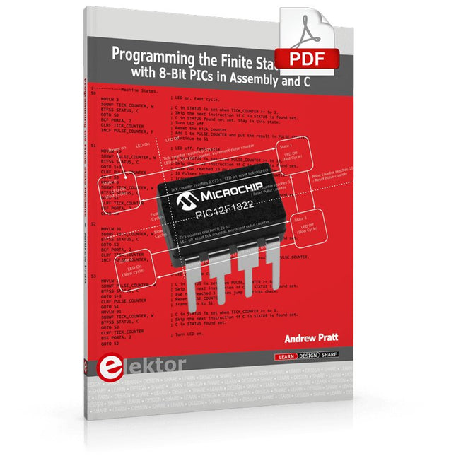
Elektor Digital Programming the Finite State Machine (E-book)
Programming the Finite State Machine with 8-Bit PICs in Assembly and C Andrew Pratt provides a detailed introduction to programming PIC microcontrollers, as well as a thorough overview of the Finite State Machine (FSM) approach to programming. Most of the book uses assembly programming, but do not be deterred. The FSM gives a structure to a program, making it easy to plan, write, and modify. The last two chapters introduce programming in C, so you can make a direct comparison between the two techniques. The book references the relevant parts of the Microchip datasheet as familiarity with it is the best way to discover detailed information. This book is aimed at Microsoft Windows and Linux users. To keep your costs to a minimum and to simplify the toolchain, specific applications are provided as a free download to enable you to use an FTDI serial lead as the programmer. The assembler used is the open-source "gpasm". All programming can be done in a text editor. There are detailed instructions on how to perform the necessary installations on Windows, Linux Debian, and derivatives such as Ubuntu and Fedora. For programming in C, Microchip's XC8 compiler is used from the command line. In addition to the programming applications, two serial read and serial write applications can be used for communicating with the PICs from a computer. A voltmeter project including practical instructions on building a circuit board from scratch is included. All theory is covered beforehand, including how to do integer arithmetic in assembly. Two PICs are covered: the PIC12F1822 and the PIC16F1823. Both can run at 32 MHz with an internal oscillator. You do not need to buy a factory-made development board and programmer. With relatively inexpensive parts including a serial lead, microcontroller, a few resistors, and LEDs, you can get started exploring embedded programming. Links Updated Programmer
€ 32,95
Members: € 29,66
-

Elektor July/August 2026 (EN)
Elektor GREEN and GOLD members can download their digital edition here. Not a member yet? Click here. MultiRF Dev BoardA Platform for Evaluating Short- and Long-Range Wireless Protocols Elektor at 65Disrupting Electronics Since 1961 Wi-Fi-Based Person Detection on an ESP32When Your Router Becomes a Motion Sensor Wireless ScalesFour Small Scales = One Big Scale Walter, the Compact IoT ModuleESP32-S3 SoC, LTE-M/NB-IoT 5G Modem, and GNSS Receiver 3- and 4-Wire RTD Sensors ConditioningWith Full-Scale Adjustment and Cable Compensation 3-in-1 2-Channel Oscilloscope/Generator/MultimeterA Review of The Fnirsi 2D15P electronica Fast Forward 2026 Invites Startups and Industry Partners EcologgingA Modular Environmental IoT Station for Field Research Wireless Connectivity in Medical ApplicationsAlways on the Pulse with Bluetooth LE AudiotronicsHum Reduction Increasing Agricultural Efficiency with AI Modeling and SensorsBoosting Agricultural Productivity OPC UA — An OverviewPlatform-Independent Data Exchange Redox Meter Instrumentation Amplifier for Physics and Engineering Experiments Active Differential Audio FiltersFor Professional Crossovers and More Elektor Community Perspectives on IoT & Sensors Telegram-Controlled Water Heater Interface ModuleA Solution Based on an ESP32 and Arduino Software 2026: An AI OdysseyWhatever Happened to Fuzzy Logic? Err-lectronics Alarm Signal Injector Plus PowerTools for Finding Broken Wires
€ 14,90
-

Elektor Digital Elektor Mars/Avril 2022 (PDF)
Construisez votre contrôleur RISC-VDébuter sur le noyau logiciel RISC-V NEORV32 pour FPGA à faible coût Tracer des graphiques avec ArduinoC?est facile avec le traceur sériel d'Arduino Carte CLUE d'AdafruitUne solution intelligente pour les projets IoT Carte tampon pour le Raspberry Pi 400Protection des entrées/sorties Cartes Raspberry Pi RP2040 à gogo Approche DIY de la sécurité et de l'espionnage électroniqueChauffez ou refroidissez la SRAM Identification des composantsTrucs et astuces, bonnes pratiques et autres informations utiles Interrupteur sans contact DIY Démarrer en électronique? (12)Adaptation d?impédance et transformateurs Quoi de neuf dans le développement de l'embarqué ?Rust et mises à jour des déploiements IoT Infographie Les bénéfices de la 5G pour l?industrie et l?automobile Relais à bobine mobile Visite à domicileChacun son tour Voyage dans les réseaux neuronaux (4e partie)Les neurones embarqués Lévitation magnétique : encore plus simpleTroisième version : la plus compacte Programmation d'automates avec le Raspberry Pi et le projet OpenPLCVisualisation des programmes PLC avec AdvancedHMI Sur le vifEmballé, c?est pesé Sous votre radarDes microcontrôleurs que vous devriez connaître Surveillance et débogage sans filUne solution pour Arduino, ESP32 et Cie Station de mesure de température et d'humidité, au format de pocheUtilisation de modules prêts à l'emploi Réparation des batteries au lithiumÉconomisez de l'argent et augmentez la puissance ! Création d?interfaces graphiques en PythonGénérateur de mèmes Trois questions fondamentalesPourquoi, avec quoi, avec qui ? Hexadoku
€ 10,95


