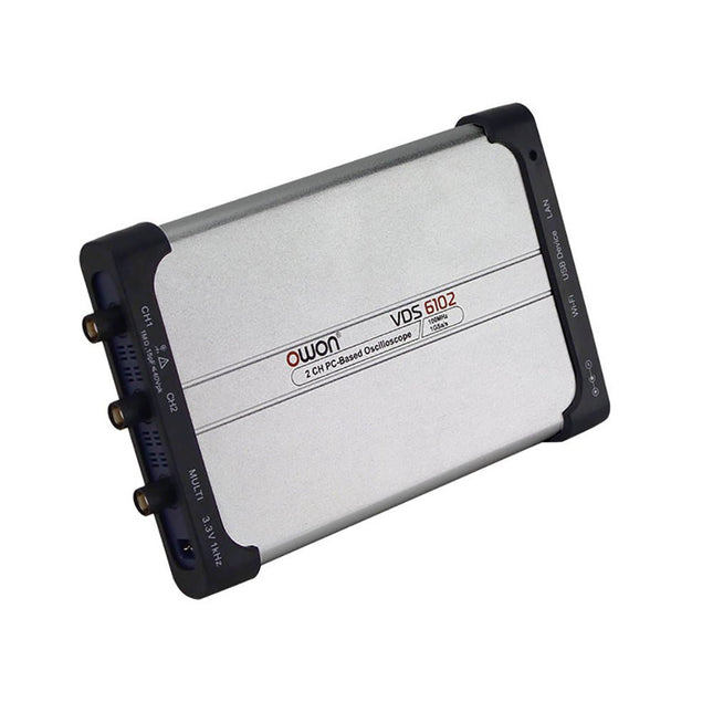
The OWON VDS6000 Series PC Oscilloscope combines powerful performance with a sleek, ultra-thin design. With 100 MHz bandwidth, 1 GSa/s real-time sampling, and up to 14-bit resolution, it delivers highly accurate measurements. The built-in 5 MHz function generator, USB-C power supply, and optional WiFi connectivity make it incredibly versatile.
Compatible with Windows, Linux, Android, and iOS, the VDS6000 is perfect for labs, fieldwork, and remote diagnostics – compact, flexible, and ready for any challenge.
Features
Bandwidth: 100 MHz
Vertical resolution: 14 bits
Rise time: ≤3.5 ns
Memory: 10 Mpts
Number of channels: 2 channels + 1 channel function generator
Horizontal scale: 5ns - 100s/div
Sample rate: Max. 1 GSa/s
Maximum voltage: 40 V (peak - peak)
Automatic measurements: Vpp, Vavg, Vamp, Vrms, Freq, Period, Vmax, Vmin, Vtop, Vbase, Overshoot, Preshoot, Rise Time,
Connectivity: USB-C, LAN, Wifi (optional)
Fall Time, Delay A→B↑, Delay A→B↓, +Width, -Width, +Duty, -Duty
Bandwidth: 5 MHz
Sample rate: 25 MSa/s
Standard waveforms: Sine (0.1 Hz - 5 MHz), Square (0.1 Hz - 200 kHz), Ramp (1 Hz - 10 kHz), Pulse (1 Hz - 10 kHz)
Resolution: 10 bits
DC offset range (AC + DC): ±2.5 V
Amplitude range: 10 mVpp - 5 Vpp
Dimensions: 190 x 120 x 18 mm
Weight: 380 g
Downloads
Manual
Quick Guide
PC Software
MacOS Software
Open-Source-Code mit Arduino IDE und PlatformIO
Autonomes Fahren: GPS, Accelerometer, Gyroskop
PS3-Controller
Mikrocontroller wie der Arduino und Einplatinenrechner wie der Raspberry Pi haben sich zu beliebten Komponenten entwickelt. Dritter im Bunde ist der ESP32 der Firma Espressif. Mikrocontroller dieser Baureihe zeichnen sich durch eine Vielzahl implementierter Funktionen aus, die bei einem Arduino konventioneller Prägung mit einem Atmel-AVR-Mikrocontroller erst mit weiterer Hardware möglich sind. Prominentes Beispiel sind hier die WiFi- und Bluetooth-Funktionalitäten. Gegenüber einem Raspberry Pi zeichnen sie sich durch einen deutlich geringeren Preis aus.
Allgemeine Informationen für die Realisierung eines Roboterauto-Projekts mit dem ESP32 sind leicht zu finden. Dabei handelt es sich aber oft nur um Ausführungen zu einem Teilaspekt, ohne inhaltliche oder funktionale Abstimmung. So ist nicht nur die Beschaffung der benötigten Informationen mühselig und zeitaufwändig, sie kann auch außerordentlich fehlerträchtig sein.
Ansatzpunkt dieses Buches ist, diese Lücke zu schließen. Es geht auf verschiedene Möglichkeiten eines Chassis ein, vermittelt nötige Kenntnisse und führt schrittweise von einer einfachen Motorsteuerung zu einem komplexen sensor- und sprachgesteuerten Roboterauto. Hacks rund um GPS und eine PlayStation 3 runden die Sache ab.
Inhalt
Bei der Reihenfolge der Kapitel wurde versucht – beginnend bei der Darstellung von grundlegenden Informationen – über die Lösung einfacher Aufgaben zu etwas anspruchsvolleren Techniken zu führen.
Der Mikrocontroller ESP32
Die Software erstellen
Die Stromversorgung
Rund um die Hardware
Das Chassis
Der Gleichstrommotor
Kabellose Steuerung über WiFi
Mit Sensoren Hindernisse erkennen
Eine eigene Roboterauto-App
Servo und Lichtsensor
GPS
Accelerometer / Gyroskop
PS3-Controller
Roboterauto-App
Hinweis zur Software
Die Dateien haben das Suffix (.cpp). Grund ist die Entwicklung mit PlatformIO. Mit Copy & Paste sollten sie auch in der Arduino-IDE verwendet werden können.
Vom Messwert zur stabilen Entscheidung
Wie wird aus einem einfachen Mikrocontroller ein intelligentes System, das Sensorwerte erfasst, verarbeitet und sinnvoll darauf reagiert? Dieses Buch zeigt es Ihnen Schritt für Schritt – verständlich, praxisnah und ohne unnötige Vorkenntnisse.
Sie beginnen mit den Grundlagen der digitalen und analogen Ein- und Ausgänge. Anschließend lernen Sie, wie Sensorwerte gelesen, geglättet und zuverlässig bewertet werden. Anschauliche Beispiele erklären, warum einzelne Messwerte oft täuschen können und wie Mittelwertbildung, Hysterese und einfache Entscheidungsregeln für stabile Ergebnisse sorgen. Nach und nach erweitern Sie Ihre Projekte um Displays, I²C-Kommunikation und mehrere vernetzte Mikrocontroller. So entstehen verteilte Systeme, in denen Raspberry Pi Pico und ATtiny-Controller Daten austauschen und gemeinsam Aufgaben übernehmen.
Im fortgeschrittenen Teil erhalten Sie einen leicht verständlichen Einstieg in Merkmalsbildung, Datenvorverarbeitung, hybride Entscheidungsmodelle und TinyML-nahe Anwendungen. Dabei verbinden Sie klassische Regelungstechnik mit modernen datenbasierten Methoden.
Alle Projekte werden von ausführlich kommentierten Programmen in C und MicroPython begleitet. Das Buch richtet sich an Einsteiger, Maker, Studierende und alle, die Embedded-Systeme von Grund auf verstehen möchten.
Am Ende können Sie eigene Systeme entwickeln, die nicht nur messen, sondern Informationen auswerten, zuverlässige Entscheidungen treffen und gezielt reagieren.
Oscilloscope, multimeter and waveform generator in the same battery-powered device, to work on the go.
Features
Oscilloscope + multimeter + waveform generator, multifunction in one
3.5-inch high-resolution, high-contrast colour LCD display, suitable for outdoor use
18650 lithium battery, comprehensive power consumption ≤3 W, can work continuously for about 6 hours
USB-C interface, support power bank, support PC software connection
Self-calibration function
SCPI supported, facilitate secondary development
Specifications
Oscilloscope
Bandwidth
70 MHz
Channels
2-ch Oscilloscope + 1-ch Generator
Sample Rate
250 MSa/s
Acquisition Model
Normal, Peak detect
Record Length
8K
Display
3.5-inch LCD
Waveform Refresh Rate
10,000 wfrms/s
Input Coupling
DC, AC, and Ground
Input Impedance
1 MΩ ±2%, in parallel with 16pF±10pF
Probe Attenuation Factors
1X,10X,100X,1000X,10000X
Max. input Voltage
400 V (DC+AC, PK-PK, 1MΩ input impedance) (10:1 probe attenuation)
Bandwidth Limit (typical)
20 MHz
Horizontal Scale
5 ns/div - 1000 s/div, step by 1 - 2 - 5
Vertical Sensitivity
10 mV/div - 10 V/div
Vertical Resolution
8 bits
Trigger Type
Edge
Trigger Modes
Auto, Normal, single
Automatic Measurement
Period, Frequency, Mean, PK-PK, Max, Min
Cursor Measurement
ΔV, ΔT, ΔT& ΔV between cursors
Communication Interface
USB Type-C
Multimeter
Max. Resolution
20,000 counts
Testing Mode
Voltage, Current, Resistance, Capacitance, Diode, and Continuity test
Input Impedance
10 MΩ
Max Input Voltage
AC: 750 V | DC: 1000 V
Max Input Current
DC: 10 A | AC: 10 A
Diode
0-2 V
Waveform Generator
Frequency Output
Sine
0.1 Hz - 25 MHz
Square
0.1 Hz - 5 MHz
Ramp
0.1 Hz - 1 MHz
Pulse
0.1 Hz - 5 MHz
Arbitrary
0.1 Hz - 5 MHz
Sampling Rate
125 MSa/s
Channel
1-ch
Amplitude Range
20 mVpp - 5 Vpp
Waveform Length
8K
Vertical Resolution
14 bits
Output Impedance
50Ω
Downloads
User Manual for HDS200 Series
SCPI Protocol for HDS200 Series
Quick Guide for HDS200 Series
PC Software for OWON HDS200 Series
The OWON HDS2202s is a portable 3-in-1 multifunctional tester, which can be used as a 2-ch oscilloscope with a bandwidth of 200 MHz, multimeter and signal generator. It features a high-contrast 3.5-inch color display suitable for outdoor facility maintenance, rapid on-site measurement, automobile maintenance, power detection. etc. Features Oscilloscope + multimeter + waveform generator, multifunction in one 3.5-inch high-resolution, high-contrast color LCD display, suitable for outdoor use 18650 lithium battery, can work continuously for 3-6 hours USB Type-C interface, support power bank, support PC software connection Self-calibration function SCPI supported, facilitate secondary development Specifications Bandwidth 200 MHz Channels 2-ch Oscilloscope + 1-ch Generator Sample Rate 1 GSa/s Acquisition Model Normal, Peak detect Record Length 8K Display 3.5-inch LCD Waveform Refresh Rate 10,000 wfrms/s Input Coupling DC, AC, and Ground Input Impedance 1 MΩ ±2%, in parallel with 16pF ±10pF Probe Attenuation Factors 1X,10X,100X,1000X,10000X Max. input Voltage 400 V (DC+AC, PK-PK, 1MΩ input impedance) (10:1 probe attenuation) Bandwidth Limit (typical) 20 MHz Horizontal Scale 2ns/div - 1000s/div, step by 1 - 2 - 5 Vertical Sensitivity 10mV/div - 10V/div Vertical Resolution 8 bits Trigger Type Edge Trigger Modes Auto, Normal, single Automatic Measurement Frequency, Period, Amplitude, Max, Min, Mean, PK-PK Cursor Measurement ΔV, ΔT, ΔT&ΔV between cursors Communication Interface USB Type-C Multimeter Specifications Max. Resolution 20,000 counts Testing Mode Voltage, Current, Resistance, Capacitance, Diode, and Continuity test Input Impedance 10 MΩ Max Input Voltage AC 750 V, DC 1000 V Max Input Current DC: 10 A, AC: 10 A Diode 0-2 V Waveform Generator Specifications Frequency Output Sine 0.1 Hz - 25 MHz Square 0.1 Hz - 5MHz Ramp 0.1 Hz - 1 MHz Pulse 0.1 Hz - 5 MHz Arbitrary 0.1 Hz - 5 MHz Sampling Rate 125 MSa/s Channel 1-ch Amplitude Range (high impedance) 20 mVpp - 5 Vpp Waveform Length 8K Vertical Resolution 14 bits Output Impedance 50Ω Included 1x OWON HDS2202s 1x Power adapter 1x USB cable 1x Passive probes 2x Crocodile clip cable 1x Set of multimeter probes (one red and one black) 1x User manual 1x Probe correction adjustment knife Downloads User Manual Specifications SCPI Protocol Quick Guide Software
Practical Projects and Programs
With Experimenting with Red Pitaya STEMlab Gen 2, Red Pitaya goes beyond a versatile board. It becomes a powerful laboratory instrument for precision measurement, analysis, and control.
From the fundamentals of electronic project development, monitoring, control, and design to testing, this book walks you step-by-step through everything you need to know to harness the full potential of Red Pitaya hardware and software.
The book presents real-time, FPGA-based projects that are developed on a PC using the Vivado environment, then transferred to the Red Pitaya for execution and testing.
You will learn about enhanced performance, expanded I/O capabilities, improved FPGA features, and advanced connectivity options that open up new frontiers for precision measurement, monitoring, and control in your embedded applications.
Inside the book you will discover:
A deep dive into Red Pitaya architecture and hardware design
Electronic experiments using Red Pitaya for measurement and monitoring
Hands-on projects using the Python programming language
Practical guidance for FPGA programming using Red Pitaya
Red Pitaya FPGA projects using the Verilog HDL under Vivado IDE
Practical design of electronic projects including measurement and testing
Step-by-step examples that bridge theory and real-world implementation
Whether you are designing your own electronic circuits, developing signal analysis tools, or creating real-time control or monitoring systems, this book provides you the knowledge and confidence you need to fully learn and customize the Red Pitaya platform.
OWON VDS1022I 2-channel USB oscilloscope (25 MHz) is a oscilloscope for use with a computer. It is powered by USB and has a small size, making it easy to take it with you. The oscilloscope is very economical. It has a shielded USB connection, reducing interference and protecting the computer against over-voltage. The multi port on the scope can be used for external triggering, trigger out or Pass / Fail output.
Features
25 MHz bandwidth, and max 1 GS/s real-time sample rate
10M record length
Friendly UI: FFT, or X-Y, and waveform 2 views displayed on the same screen
Multi-trigger option: edge, video, slope, pulse, and alternate
USB isolation – less signal inference, more PC protection
USB bus powering, and LAN remote control (optional)
Ultra-thin body design, easy portability
Specifications
Bandwidth
25 MHz
Channel
2+1 (multi)
Sample Rate
100 MSa/s
Horizontal Scale (s/div)
5 ns/div~100s/div, step by 1~2~5
Record Length
5K
Max Input Voltage
400 V (PK - PK)
(DC+AC, PK - PK)
40 V (PK - PK) (DC+AC, PK - PK)
Vertical Resolution (A/D)
8 bits (2 channels simultaneously)
Model
VDS1022I
Vertical Sensitivity
5 mV/div~5 V/div
Trigger Type
Edge, Pulse, Video, Slope, and Alternate
Trigger Mode
Auto, Normal, and Single
Acquisition Mode
Sample, Peak Detect, and Average
Waveform Math
+, -, ×, ÷, invert, FFT
Communication Interface
USB 2.0 (isolation)
Multi-function
Interface
Signal Type
Level Standard
TTL
Power Supply
5.0 V/1 A
Power Consumption
≤2.5 W
Dimensions (W × H × D)
170 x 120 x 18 mm
Weight
0.26 kg
Included
1x OWON VDS1022I oscilloscope
1x CD-ROM
1x Quick start guide
2x Oscilloscope probe
1x Probe tool
1x Power adapter
1x USB cable
1x Silicone case protectors
1x Power cable
Downloads
Datasheet
User manual
SCPI protocol
USB driver
Siglent's SDS2000X Plus series Digital Storage Oscilloscopes are available in bandwidths of 100 MHz, 200 MHz, and 350 MHz, have a maximum sample rate of 2 GSa/s, a maximum record length of 200 Mpts/ch, and up to 4 analog channels + 16 digital channels mixed-signal analysis ability.
The SDS2000X Plus series employs Siglent’s SPO technology with a maximum waveform capture rate of up to 120,000 wfm/s (normal mode, up to 500,000 wfm/s in Sequence mode), 256-level intensity grading display function plus a color temperature display mode. It also employs an innovative digital trigger system with high sensitivity and low jitter. The trigger system supports multiple powerful triggering modes including serial bus triggering. History waveform recording, Sequence acquisition, Search and Navigate functions allow for extended waveform records to be captured, stored, and analyzed. An impressive array of measurement and math capabilities, options for a 50 MHz waveform generator, as well as serial decoding, mask test, bode plot, and power analysis are also features of the SDS2000X Plus. A 10-bit acquisition mode helps to satisfy applications that require more than 8-bit resolution.
The large 10.1’’ capacitive touch screen supports multi-touch gestures, while the remote web control, mouse and external keyboard support greatly improve the operating efficiency of the SDS2000X Plus.
Features
100 MHz, 200 MHz, 350 MHz (upgradable to 500 MHz) models
Real-time sampling rate up to 2 GSa/s
Record length up to 200 Mpts
Serial bus triggering and decoder, supports I²C, SPI, UART, CAN, LIN, CAN FD, FlexRay, I²S and MIL-STD-1553B
Provide 10 bit mode, Vertical and Horizontal Zoom
Capacitive touch screen supports multi-touch gestures
Siglent SDS2000X Plus Oscilloscopes
SDS2102X Plus
SDS2104X Plus
SDS2204X Plus
SDS2354X Plus
Bandwidth
100 MHz
100 MHz
200 MHz
350 MHz
Channels
2
4
4
4
Real-time sampling rate
2 GSa/s
2 GSa/s
2 GSa/s
2 GSa/s
Capture rate
120,000 wfm/s
120,000 wfm/s
120,000 wfm/s
120,000 wfm/s
Memory depth
200 Mpts/ch
200 Mpts/ch
200 Mpts/ch
200 Mpts/ch
Included
Siglent SDS2102X Plus Oscilloscope
Passive probes
Power cord
USB cable
Manual
Downloads
Datasheet
Manual
Quick guide
Manual
Firmware
This complete STM32 microcontroller programming course features a textbook, a component kit, hands-on projects, and a comprehensive online course. It is ideal for step-by-step learning of embedded systems programming in MicroPython using a practical, hands-on approach.
A Practical Introduction to Embedded Systems with the STM32
This course is designed for people who are new to embedded systems and looking for a structured, example-driven way to get started. A kit of parts comprising LEDs and resistors, switches, sensors and actuators, displays, a breadboard and wires, and more is included. These are used in the course to illustrate example applications.
No prior experience with MicroPython or embedded development is required. Each section features hands-on examples and mini projects designed to reinforce key concepts and inspire deeper exploration. By the end of the course, you’ll be able not only to reproduce the examples but also to build on them with your own ideas and applications.
What Will You Learn?
Microcontroller programming in MicroPython on the STM32 using the Thonny IDE
Working with Digital I/O, read buttons and encoders, control LEDs and relays
Read analog inputs, voltages, and analog sensors
Generating analog output signals and PWM
Use serial communication like UART, I²C and SPI to control displays and read digital sensors and SD cards
Managing time
Working with interrupts
Real-time sensor input and control via buttons, LEDs, and displays
Control actuators like relays and servo motors
Who Is It For?
Students and self-learners exploring embedded systems
Makers and IoT enthusiasts looking to improve their hardware skills
Educators and trainers seeking ready-to-teach material
What's Inside the Box?
Access to the full course on the Elektor Academy Pro Learning Platform
STM32 NUCLEO-F411RE microcontroller board
Book: MicroPython for STM32
Downloadable project files for every module
Component Box:
2× LED, red, 5 mm
LED, green, 5 mm
3× Resistor, 470 Ω, 0.25 W
LDR
Potentiometer, 10 kΩ, linear
Pushbutton
Rotary encoder module
Relay module
DHT22 Humidity & Temperature Sensor
TM1637-compatible 4-digit 7-segment display
MPU-6050 IMU with headers
SSD1306-compatible I²C OLED display
Micro SD card adapter with header
Buzzer
SG90 Micro Servo
ILI9341-compatible SPI 240×320 TFT display
20× Jumper wires
Breadboard
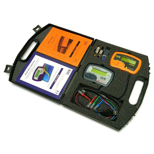
This pack contains the LCR45 Passive Component Impedance Meter, great for advanced hobbyists and professionals. It also contains the very popular DCA Pro (model DCA75), fantastic for component identification, pinout identification, detailed characteristic measurement and curve tracing on a PC. Complete with USB cable and software on a USB flash drive.
DCA75
Building on the continued success of Peak's existing component identification and analysis instruments, the DCA Pro brings an array of exciting new features for the hobbyist and professional alike.
The DCA Pro is an advanced new design that features a graphics display, USB communications, PC Software and an enhanced component identification library.
Automatic component type identification
Automatic pinout identification (connect any way round)
The DCA Pro supports all the components that the popular Peak Atlas DCA55 supports, but adds plenty more. Components supported include:
Transistors (including Darlingtons), Silicon and Germanium types. Measures gain, Vbe and leakage
MOSFETs, enhancement mode and depletion mode types. Measure on-threshold (at 5 mA) and approx transconductance (for span of 3-5 mA)
JFETs, including normally off SiC types. Measures pinch-off voltage (at 1 uA) and approx transconductance (for span of 3-5 mA)
IGBTs (insulated gate bipolar transistors). Measures on-threshold (at 5 mA)
Diodes and Diode networks
LEDs and bicolour LEDs (2 lead and 3 lead types)
Zener Diodes with measurement of zener voltage up to 9 V at 5 mA
Voltage regulators (measures regulation voltage, drop-out voltage, quiescent current)
Triacs and Thyristors that require less than 10 mA of gate current and holding current
Stand-alone or with a PC
The instrument can be used stand-alone or connected to a PC. Either way, the DCA Pro will automatically identify the component type, identify the pinout and also measure a range of component parameters such as transistor gain, leakage, MOSFET and IGBT threshold voltages, pn characteristics and much more.
Curve Tracing
When connected to a PC using the supplied USB cable, a range of low current curve-tracing functions can be performed. Various graph types are available, with more to follow:
Bipolar transistor output characteristics, IC vs VCE
Bipolar transistor gain characteristics, HFE vs VCE
Bipolar transistor gain characteristics, HFE vs IC
MOSFET and IGBT output function, ID vs VDS
MOSFET and IGBT transfer function, ID vs VGS
JFET output function, ID vs VDS
JFET transfer function, ID vs VGS
Voltage regulator, VOUT vs VIN
Voltage regulator, IQ vs VIN.
PN junction I/V curves, forward and reverse options (for Zener diodes)
Curve tracing is performed using test parameters in the range of +/-12 V or +/-12 mA. All curve-tracing data can be instantly pasted into Excel for further graphing and analysis. PC Software is included with the DCA Pro on a Peak USB memory stick. Software designed for Windows 7 and higher (all 32 or 64 bit).
LCR45
A great handheld LCR analyzer that can measure the value of your passive component (inductor, capacitor or resistor) and also measure the detailed impedance in a number of modes. The LCR45 offers enhanced measurement resolution (better than 0.1 uH!) whilst also giving you continuous fluid measurements. Additionally, the test frequencies of DC, 1 kHz, 15 kHz and 200 kHz can be set to automatic or manual modes. Supplied with removable gold plated hook probes, battery and user guide. Compatible with standard 2 mm test connectors. Not designed for in-circuit use.
Automatic or manual component type selection: Inductor, Capacitor or Resistor
Automatic or manual test frequency selection: DC, 1 kHz, 15 kHz and 200 kHz
Inductance from 0.1 uH to 10 H
Capacitance from 0.1 pF to 10,000 uF
Resistance from 0.1 Ohm to 2 MOhm
Inductance measurement also shows DC winding resistance
Display of "Component type and values", "Complex Impedance", "Magnitude/Phase" and "Admittance"
Test frequency displayed for all measurements
Typical accuracy of 1.5% for inductors and capacitors (see spec table for details)
Typical accuracy of 1% for resistors
Test lead complete with gold plated 2 mm plugs and sockets
Supplied with removable gold plated hook probes
Included
LCR45
DCA75
Extra GP23 Battery
Extra AAA cell
Dual Carry Case
Open-Source-Code mit Arduino IDE und PlatformIO
Autonomes Fahren: GPS, Accelerometer, Gyroskop
PS3-Controller
Mikrocontroller wie der Arduino und Einplatinenrechner wie der Raspberry Pi haben sich zu beliebten Komponenten entwickelt. Dritter im Bunde ist der ESP32 der Firma Espressif. Mikrocontroller dieser Baureihe zeichnen sich durch eine Vielzahl implementierter Funktionen aus, die bei einem Arduino konventioneller Prägung mit einem Atmel-AVR-Mikrocontroller erst mit weiterer Hardware möglich sind. Prominentes Beispiel sind hier die WiFi- und Bluetooth-Funktionalitäten. Gegenüber einem Raspberry Pi zeichnen sie sich durch einen deutlich geringeren Preis aus.
Allgemeine Informationen für die Realisierung eines Roboterauto-Projekts mit dem ESP32 sind leicht zu finden. Dabei handelt es sich aber oft nur um Ausführungen zu einem Teilaspekt, ohne inhaltliche oder funktionale Abstimmung. So ist nicht nur die Beschaffung der benötigten Informationen mühselig und zeitaufwändig, sie kann auch außerordentlich fehlerträchtig sein.
Ansatzpunkt dieses Buches ist, diese Lücke zu schließen. Es geht auf verschiedene Möglichkeiten eines Chassis ein, vermittelt nötige Kenntnisse und führt schrittweise von einer einfachen Motorsteuerung zu einem komplexen sensor- und sprachgesteuerten Roboterauto. Hacks rund um GPS und eine PlayStation 3 runden die Sache ab.
Inhalt
Bei der Reihenfolge der Kapitel wurde versucht – beginnend bei der Darstellung von grundlegenden Informationen – über die Lösung einfacher Aufgaben zu etwas anspruchsvolleren Techniken zu führen.
Der Mikrocontroller ESP32
Die Software erstellen
Die Stromversorgung
Rund um die Hardware
Das Chassis
Der Gleichstrommotor
Kabellose Steuerung über WiFi
Mit Sensoren Hindernisse erkennen
Eine eigene Roboterauto-App
Servo und Lichtsensor
GPS
Accelerometer / Gyroskop
PS3-Controller
Roboterauto-App
Hinweis zur Software
Die Dateien haben das Suffix (.cpp). Grund ist die Entwicklung mit PlatformIO. Mit Copy & Paste sollten sie auch in der Arduino-IDE verwendet werden können.
The OWON HDS2102s is a portable 3-in-1 multifunctional tester, which can be used as a 2-ch oscilloscope with a bandwidth of 100 MHz, multimeter and signal generator. It features a high-contrast 3.5-inch color display suitable for outdoor facility maintenance, rapid on-site measurement, automobile maintenance, power detection. etc.Features
Oscilloscope + multimeter + waveform generator, multifunction in one
3.5-inch high-resolution, high-contrast color LCD display, suitable for outdoor use
18650 lithium battery, can work continuously for 3-6 hours
USB Type-C interface, support power bank, support PC software connection
Self-calibration function
SCPI supported, facilitate secondary development
Specifications
Bandwidth
100 MHz
Channels
2-ch Oscilloscope + 1-ch Generator
Sample Rate
500 MSa/s
Acquisition Model
Normal, Peak detect
Record Length
8K
Display
3.5-inch LCD
Waveform Refresh Rate
10,000 wfrms/s
Input Coupling
DC, AC, and Ground
Input Impedance
1 MΩ ±2%, in parallel with 16pF ±10pF
Probe Attenuation Factors
1X,10X,100X,1000X,10000X
Max. input Voltage
400 V (DC+AC, PK-PK, 1MΩ input impedance) (10:1 probe attenuation)
Bandwidth Limit (typical)
20 MHz
Horizontal Scale
2ns/div - 1000s/div, step by 1 - 2 - 5
Vertical Sensitivity
10mV/div - 10V/div
Vertical Resolution
8 bits
Trigger Type
Edge
Trigger Modes
Auto, Normal, single
Automatic Measurement
Frequency, Period, Amplitude, Max, Min, Mean, PK-PK
Cursor Measurement
ΔV, ΔT, ΔT&ΔV between cursors
Communication Interface
USB-C
Multimeter Specifications
Max. Resolution
20,000 counts
Testing Mode
Voltage, Current, Resistance, Capacitance, Diode, and Continuity test
Input Impedance
10 MΩ
Max Input Voltage
AC 750 V, DC 1000 V
Max Input Current
DC: 10 A, AC: 10 A
Diode
0-2 V
Waveform Generator Specifications
Frequency Output
Sine
0.1 Hz - 25 MHz
Square
0.1 Hz - 5MHz
Ramp
0.1 Hz - 1 MHz
Pulse
0.1 Hz - 5 MHz
Arbitrary
0.1 Hz - 5 MHz
Sampling Rate
125 MSa/s
Channel
1-ch
Amplitude Range (high impedance)
20 mVpp - 5 Vpp
Waveform Length
8K
Vertical Resolution
14 bits
Output Impedance
50Ω
Included
1x OWON HDS2102s
1x Power adapter
1x USB cable
1x Passive probes
2x Crocodile clip cable
1x Set of multimeter probes (one red and one black)
1x User manual
1x Probe correction adjustment knife
Downloads
User Manual
Specifications
SCPI Protocol
Quick Guide
Software