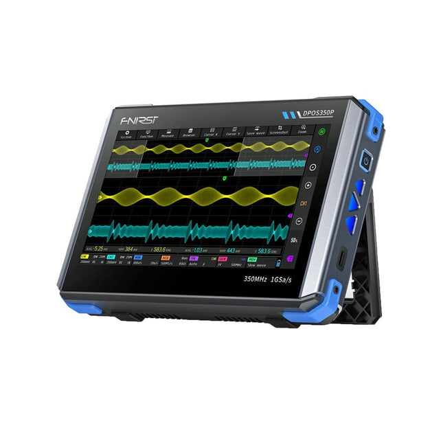
2 Channels • 350 MHz • 1 GSa/s • 50,000 wfm/s • 7 inch Touchscreen
The FNIRSI DPOS350P is a sleek 4-in-1 powerhouse in tablet form! This compact and portable device packs serious functionality: it combines a 2-channel oscilloscope (350 MHz), a signal generator (50 MHz), a frequency response analyzer (50 MHz), and a spectrum analyzer (200 kHz–350 MHz) – all in one unit.
Whether you're in R&D, troubleshooting, or field testing, the DPOS350P delivers the tools you need to measure, generate, analyze, and visualize electronic signals with precision and clarity. Its responsive high-resolution touchscreen and intuitive controls make signal analysis fast, flexible and efficient.
Features
Powerful Multi-Function Integration
350 MHz 2-channel oscilloscope with 1 GSa/s real-time sampling
50 MHz signal generator with 14 standard + custom waveforms
Spectrum analyzer (200 kHz–350 MHz): Perfect for EMI, RF & HF testing
Frequency response analyzer (FRA) up to 50 MHz
High-Performance Waveform Capture
50,000 wfm/s refresh rate for real-time signal clarity
350 MHz bandwidth (single-channel mode)
Detects rare and low-probability anomalies
Crisp Display & Smooth Operation
7" IPS touchscreen (1024 x 600 resolution)
Switch between grayscale and color temperature display
Easy to operate in various test environments
Reliable, Protected & Fast-Charging
High-voltage protection up to 400 V
Fast charging with QC 18 W (full charge in 2 hours)
Built for stable long-term operation
Data Storage & Export
Save up to 500 waveform records + 90 screenshots
USB export for easy reporting and offline analysis
Specifications
General
Display
7 inch (IPS full viewing angle)
Resolution
1024 x 600 pixels
Interaction mode
Capacitive touch screen
Total power consumption
10 W
Power-on configuration
5 presets
Charging
QC 18 W, 12 V/1.5 A (USB-C)
Battery
3.7 V, 8000 mAh lithium battery
Battery life
approx. 3 hours in operation, 5 hours standby
Heat dissipation
Air cooling
Expansion interface
USB data port
Automatic shutdown
15~60 minutes / off
Firmware upgrade
Support .iso image upgrade
Languages
English / Portuguese / Russian / Chinese
Dimensions
190 x 128 x 37 mm
Oscilloscope
Analog channels
2
Analog bandwidth
350 MHz
Rise time
1ns
Real-time sampling rate
1 GSa/s
Memory depth
60 Kpts
Input impedance
1 MΩ / 14PF
Time base range
5ns ~ 50s
Roll time base
50ms ~ 50s
Vertical sensitivity
2 mV ~ 20 V (1X)
Vertical range
16 mV ~ 160 V (1X)
DC accuracy
±2%
Time accuracy
±0.01%
Input coupling
DC / AC
Probe attenuation
1X / 10X / 100X
Hardware bandwidth limit
150M / 20M
High resolution mode
8bit ~ 16bit
Parameter measurements
12 types
Cursor measurement
Time, period, frequency, level, voltage
Trigger detection
Digital trigger
Trigger channel
CH1 / CH2
Trigger mode
Auto / Single / Normal
Trigger edge
Rising edge / Falling edge
Trigger suppression
L1 ~ L3
Trigger level
Manual / automatic 10% ~ 90%
Screenshot storage
90 pictures
Waveform storage
500 groups
Background grid
Display / hide
Waveform movement
Coarse adjustment / fine adjustment
Overvoltage protection
Withstand voltage 400 V
Waveform brightness
Adjustable
Simple FFT display
Yes
Digital fluorescence
Yes
Color temperature display
Yes
X-Y mode
Yes
ZOOM time base
Yes
One-key automatic adjustment
Yes
One-key return to zero
Yes
Data browser
Yes
Signal Generator
Waveform types
14 standard functions + captured waveform
Frequency
0~50 MHz (sine wave only, other waveforms up to 10M/5M/3M)
Amplitude
0~5 VPP
Offset
-2.5 V ~ +2.5V
Duty cycle
0.1~99.9%
Frequency resolution
1 Hz
Amplitude resolution
1 mV
Offset resolution
1 mV
Duty cycle resolution
0.1%
Customizable captured waveform
500 groups
Frequency Response Analyzer (FRA)
Excitation signal frequency
100 Hz ~ 50 MHz
Excitation signal amplitude
0~5 VPP
Excitation signal offset
-2.5V ~ +2.5V
Excitation frequency count
20~500
Cursor measurement
Frequency / gain / phase
Operating mode
Single / cyclic
System calibration
Yes
Spectrum Analyzer
Conversion method
FFT
FFT length
4K ~ 32K
Frequency range
200 KHz ~ 350 MHz
Level range
-60 dBmV ~ +260 dBmV
Cursor measurement
Frequency / amplitude
Marking parameter
Maximum energy harmonic
Waterfall chart
Yes
3D waterfall chart
Yes
Automatic adjustment
Yes
System calibration
Yes
Included
1x FNIRSI DPOS350P Oscilloscope (4-in-1)
2x 350 MHz Probes
1x QC 18 W Fast Charger (EU)
1x USB-C Cable
1x Alligator Clip
1x Storage Bag
1x Manual
Downloads
Manual
Firmware
This bundle gives you everything you need to get started right away with the XIAO ESP32-C3 development board. Learn the fundamentals of the ESP32-C3 and build practical projects with Wi-Fi, Bluetooth, sensors, displays, PWM, Deep Sleep, and much more.
Book: Build Smart Projects with the XIAO ESP32-C3 Board
The XIAO ESP32-C3 board combines the ultra-compact form factor of the XIAO series with the full capabilities of the ESP32-C3 chip, including integrated Wi-Fi and Bluetooth 5.0. This book is a comprehensive, hands-on guide to getting the most out of this powerful yet affordable development board.
The author takes readers from the fundamentals to advanced projects. Starting with LED blinking and dimming, the book progresses to ADC and PWM for precise sensor interfacing and PWM-controlled lighting effects before moving on to building practical, real-world applications, including:
A Wi-Fi weather station with an OLED display and real-time online weather data
An ultrasonic parking assistant with audible feedback
A refrigerator monitoring probe with climate sensing and Deep Sleep for years of battery operation
A retro Pong game controlled by a touch-free sensor
A microphone-based party app that responds to claps
And much more: lighting control, reaction-time measurement, mains frequency analysis, soil moisture sensing, ambient LED lighting, and 7-segment displays
Seeed Studio XIAO ESP32C3
Seeed Studio XIAO ESP32C3 has equipped a highly-integrated ESP32-C3 chip, built around a 32-bit RISC-V chip processor with a four-stage pipeline that operates at up to 160 MHz.
The board equips highly-integrated ESP32-C3 SoC. The chip has been installed with a complete 2.4 GHz Wi-Fi subsystem which means it supports Station mode, SoftAP mode, SoftAP & Station mode, and promiscuous mode for multiple Wi-Fi applications. It works under an ultra-low power state, also supporting features of Bluetooth 5 and Bluetooth mesh. There are 400 KB SRAM & 4 MB Flash on the chip, allowing for more programming space, and bringing more possibilities to the IoT control scenarios.
Applications
Internet of Things
Wearable devices
Health monitoring
Education
Low-Power networking
Rapid prototyping
Specifications
Processor
ESP32-C3 SoC
RISC-V single-core 32-bit chip processor with a four-stage pipeline that operates at up to 160 MHz
Wireless
Complete 2.4GHz Wi-Fi subsystem
Bluetooth Low Energy 5.0/ Bluetooth Mesh
On-chip Memory
400 KB SRAM & 4 MB Flash
Interface
1x UART, 1x I²C, 1x SPI, 11x GPIO (PWM), 4x ADC
1x Reset button, 1x Boot button
Power (Typ.)
Max 3.3 V Output Current: 500 mA Test Condition: BAT Pin Input @ 3.8 V Source Capability: 3 A
Charging current: 380 mA(Fast) / 40 mA(Trickle)
Input voltage (VIN): 5 VInput voltage (BAT): 3.7 V
Deep Sleep Power Consumption
Deep Sleep Mode: 44 μA
Wi-Fi Enabled Power Consumption
Active Mode: 75 mA
Modem-sleep Mode: 25 mA
Light-sleep Mode: 4 mA
BLE Enabled Power Consumption
Modem-sleep Mode: 27 mA
Light-sleep Mode: 10 mA
Dimensions
21 x 17.8 mm
Included
1x Seeed Studio XIAO ESP32C3
1x Antenna
2x 7-pin header
Downloads
Wiki
Datasheet
This bundle contains:
Book: Build Smart Projects with the XIAO ESP32-C3 Board (normal price: €35)
Board: Seeed Studio XIAO ESP32C3 (normal price: €10)
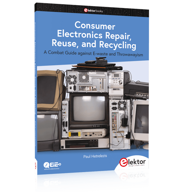
A Combat Guide against E-waste and Throwawayism
This book is for anyone who enjoys tinkering with analog and digital hardware electronics. Regardless of the sophistication of your workspace, only basic tools are required to achieve truly satisfying results. It is intended as a reference guide among other hardware repair publications you may have in your library. However, the book goes a step further than most other repair guides in addressing issues in the modern era of discarded electronics called e-waste.
E-waste should be put to good use. Producing anything new requires not just precious resources and labor, but also energy to make and deliver it to global retail shelves. Your talents and love of electronics can be put to good use by rescuing and resurrecting at least selected units from this endless stream of e-waste. Examples include either restoring through repair, or salvaging reusable electronic and mechanical components for your next project.
Smart tips are provided throughout the book, and much information is tabulated for easy reference. The book expands age-old repair and hacking techniques applied for repair on the workbench into clever methods and applications to achieve effective results with discarded or “non-servicable” electronic consumer products. The final chapter provides real-life examples using all of the previously discussed content in a summarized form for each example repair type.
Verstehen und effektiv einsetzen
Was in der Elektronik geschieht, ist mit bloßem Auge unsichtbar. Das Instrument, mit dem sich elektrische Signale präzise visualisieren lassen und die Effekte der Elektronik für uns sichtbar werden, ist das Oszilloskop.
Leider wagt man sich beim Einstieg in die Elektronik oft ohne Oszilloskop vor. Man tappt dann im Dunkeln, sowohl praktisch als auch gedanklich. Die erste Beobachtung eines elektrischen Signals auf einem Bildschirm ist eine Offenbarung. Niemand möchte dieses Erlebnis danach noch einmal missen. Es gibt kein Zurück mehr.
Wer in der Elektronik mit Freude und Verständnis vorankommen möchte, braucht unbedingt ein Oszilloskop. Dann stellt sich zunächst die Frage: Wie wählt man das richtige Oszilloskop aus? Und kaum ist diese Frage beantwortet, tauchen bereits die nächsten auf, die sich letztlich auf eine zentrale Frage reduzieren lassen: Wie nutzt man das Oszilloskop so, dass die Anzeige die Realität der Signale korrekt widerspiegelt?
Rémy Mallard ist ein leidenschaftlicher Vermittler komplexer technischer Themen mit dem Talent, diese verständlich und fesselnd zu präsentieren. In diesem Buch beantwortet er wichtige Fragen zur Verwendung eines Oszilloskops und bietet zahlreiche Anleitungen, um die elektrischen Signale elektronischer Systeme zu erforschen und zu verstehen. Dank seines verständlichen Stils und seiner praktischen Einblicke ist dieses Buch ein wertvolles Werkzeug für alle, die ihr Elektronikwissen vertiefen möchten.
Hands-on in more than 50 projects
STM32 Nucleo family of processors are manufactured by STMicroelectronics. These are low-cost ARM microcontroller development boards. This book is about developing projects using the popular STM32CubeIDE software with the Nucleo-L476RG development board. In the early Chapters of the book the architecture of the Nucleo family is briefly described.
The book covers many projects using most features of the Nucleo-L476RG development board where the full software listings for the STM32CubeIDE are given for each project together with extensive descriptions. The projects range from simple flashing LEDs to more complex projects using modules, devices, and libraries such as GPIO, ADC, DAC, I²C, SPI, LCD, DMA, analogue inputs, power management, X-CUBE-MEMS1 library, DEBUGGING, and others. In addition, several projects are given using the popular Nucleo Expansion Boards. These Expansion Boards plug on top of the Nucleo development boards and provide sensors, relays, accelerometers, gyroscopes, Wi-Fi, and many others. Using an expansion board together with the X-CUBE-MEMS1 library simplifies the task of project development considerably.
All the projects in the book have been tested and are working. The following sub-headings are given for each project: Project Title, Description, Aim, Block Diagram, Circuit Diagram, and Program Listing for the STM32CubeIDE.
In this book you will learn about
STM32 microcontroller architecture;
the Nucleo-L476RG development board in projects using the STM32CubeIDE integrated software development tool;
external and internal interrupts and DMA;
DEBUG, a program developed using the STM32CubeIDE;
the MCU in Sleep, Stop, and in Standby modes;
Nucleo Expansion Boards with the Nucleo development boards.
What you need
a PC with Internet connection and a USB port;
STM32CubeIDE software (available at STMicroelectronics website free of charge)
the project source files, available from the book’s webpage hosted by Elektor;
Nucleo-L476RG development board;
simple electronic devices such as LEDs, temperature sensor, I²C and SPI chips, and a few more;
Nucleo Expansion Boards (optional).
Open-Source-Code mit Arduino IDE und PlatformIO
Autonomes Fahren: GPS, Accelerometer, Gyroskop
PS3-Controller
Mikrocontroller wie der Arduino und Einplatinenrechner wie der Raspberry Pi haben sich zu beliebten Komponenten entwickelt. Dritter im Bunde ist der ESP32 der Firma Espressif. Mikrocontroller dieser Baureihe zeichnen sich durch eine Vielzahl implementierter Funktionen aus, die bei einem Arduino konventioneller Prägung mit einem Atmel-AVR-Mikrocontroller erst mit weiterer Hardware möglich sind. Prominentes Beispiel sind hier die WiFi- und Bluetooth-Funktionalitäten. Gegenüber einem Raspberry Pi zeichnen sie sich durch einen deutlich geringeren Preis aus.
Allgemeine Informationen für die Realisierung eines Roboterauto-Projekts mit dem ESP32 sind leicht zu finden. Dabei handelt es sich aber oft nur um Ausführungen zu einem Teilaspekt, ohne inhaltliche oder funktionale Abstimmung. So ist nicht nur die Beschaffung der benötigten Informationen mühselig und zeitaufwändig, sie kann auch außerordentlich fehlerträchtig sein.
Ansatzpunkt dieses Buches ist, diese Lücke zu schließen. Es geht auf verschiedene Möglichkeiten eines Chassis ein, vermittelt nötige Kenntnisse und führt schrittweise von einer einfachen Motorsteuerung zu einem komplexen sensor- und sprachgesteuerten Roboterauto. Hacks rund um GPS und eine PlayStation 3 runden die Sache ab.
Inhalt
Bei der Reihenfolge der Kapitel wurde versucht – beginnend bei der Darstellung von grundlegenden Informationen – über die Lösung einfacher Aufgaben zu etwas anspruchsvolleren Techniken zu führen.
Der Mikrocontroller ESP32
Die Software erstellen
Die Stromversorgung
Rund um die Hardware
Das Chassis
Der Gleichstrommotor
Kabellose Steuerung über WiFi
Mit Sensoren Hindernisse erkennen
Eine eigene Roboterauto-App
Servo und Lichtsensor
GPS
Accelerometer / Gyroskop
PS3-Controller
Roboterauto-App
Hinweis zur Software
Die Dateien haben das Suffix (.cpp). Grund ist die Entwicklung mit PlatformIO. Mit Copy & Paste sollten sie auch in der Arduino-IDE verwendet werden können.
Diese Ausgabe steht allen GOLD- und GREEN-Mitgliedern auf der ElektorMagazine-Website zum Download bereit!
Sie sind noch kein Mitglied? Hier klicken!
PIO-Programmierung des Raspberry Pi PicoNeun Befehle, viele Möglichkeiten
KI aus dem Browser befreienSo nutzen Sie KI-CLIs zum Programmieren, Kompilieren und Validieren von Embedded-Projekten
Der Scrutiny DebuggerDebuggen, Visualisieren und Testen von Embedded-C/C++ Code
Sigfox-Breakout-Board (Teil 1)Ein selbst gebautes Funk-BoB
Rauscharmes Labor-Netzteil (Teil 2)Konstruktion, Montage und praktische Implementierung
Einfacher Signalgenerator mit dem RP2040Analoge und digitale Signale für rund 10 Euro
Matter und Edge-KI für die Smart Homes der ZukunftBieten die neuesten Updates von Matter und der Aufstieg der Edge-KI Entwicklern endlich die Werkzeuge, um das versprochene intelligente und vernetzte Smart Home zu schaffen?
Die SMU für alleSiglent bringt die SMM3000X-Serie auf den Markt
DifferenzdrucksensorenVorausschauende Wartung in HLK-Systemen
Security by DesignSchadensbegrenzung durch Entwicklungsprinzipien
Embedded Security ist nicht mehr optional
CRA und PQC setzen neue Prioritäten für Embedded-SicherheitWarum auch kleine IoT- und Industrie-Unternehmen einen Upgrade-Plan benötigen
embedded world 2026Interview mit Benedikt Weyerer, Executive Director der embedded world
I3C in der PraxisMit Hardware von ST und Microchip
Das BLEnky-ProjektSchnelles Prototyping für Bluetooth-Low-Energy-Anwendungen
PulsbreitensteuerungVom einfachen Thermostat bis zum geglätteten Analogsignal
AudiotronicsKlangvolle Elektronik zum Selberbauen
ESP32-Audio-Transceiver-Board (Teil 4)Taktsynchronisation – und eine kabelgebundene Option
2026: Eine KI-OdysseeDer Vibe-Coding-Kater von 2025
Symmetrische DC-LastGleichstromlast, statisch oder dynamisch und symmetrisch
Gesichter zählen mit MaixCAMEine einfache Methode zur Erfassung von Publikumsgrößen
Lancé en mars 2012, plus les 30 millions d'exemples nanométriques du Raspberry Pi exposés. Il s’agit d’une contribution à la révolution des technologies de l’information et d’un grand stimulant pour le développement du monde de l’électronique. Le succès de la « tarte à la framboise » (traduction littérale de Raspberry Pie) est le résultat de l'industrie micro-électronique de transformation des produits.
Eben Upton, son créateur, âme à l'origine, les acheteurs étaient presque tous des makers , adultes en général. Cependant la plupart d'entre eux étaient également des ingénieurs professionnels. Rapidité, les gens sont responsables de leurs activités personnelles lors de l'utilisation du Raspberry Pi avec une plateforme informatique stable, et ils sont également adoptés pour leur métier.
La Fondation Raspberry Pi édite un magazine édité par la communauté Raspberry Pi : le MagPi (en anglais). Le magazine aborde les passions selon la nature du numérique nano-ordonné et global. Il contient des bancs d'essai de nouveaux produits, de nombreux tutoriels et un grand nombre de projets. Les membres de la communauté Raspberry Pi participent à leur expérience.
La maison d'édition Elektor s'associe à la Fondation Raspberry Pi pour la publication dans le magazine français MagPi. Il est conçu pour assembler 84 projets publics du MagPi en développant l'utilisation du Raspberry Pi et son inspiration.
Grâce à la taille fine et aux possibilités du Raspberry Pi, les créateurs du monde sont fiers des idées des plus folles.
Partez en voyage dans un monde où est faisable !
Le Raspberry Pi à toutes les sauces pour ?
s'inspirateur des projets réalisés par les membres de la communauté
dénicher des utilisations inouïes
découvrir des accessoires et technologies diverses
entrer dans une communauté intégrée et active de Raspberry Pi
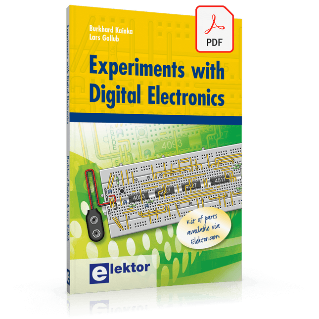
The field of digital electronics is central to modern technology. This e-book presents fundamental circuits using gates, flip-flops and counters from the CMOS 4000 Series. Each of the 50 experiments has a circuit diagram as well as a detailed illustration of the circuit’s construction on solderless breadboard.
Learning these fundamentals is best done using practical experiments. Building these digital circuits will improve your knowledge and will be fun to boot. Many of the circuits presented here have practical real-life applications. With a good overview of the field, you’ll be well equipped to find simple and cost-effective solutions for any application.
The e-book is targeted essentially at students, trainees and anyone with an interest in and requiring an introduction to digital control electronics. Moreover, the knowledge gleaned here is the foundation for further projects in the field of microcontrollers and programming.
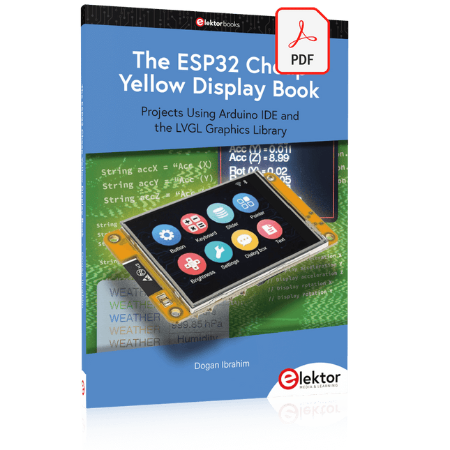
Projects Using Arduino IDE and the LVGL Graphics Library
The ESP32 is probably one of the most popular microcontrollers used by many people, including students, hobbyists, and professional engineers. Its low cost, coupled with rich features makes it a popular device to use in many projects. Recently, a board called the ESP32 Cheap Yellow Display (CYD for short) is available from its manufacturers. The board includes a standard ESP32 microcontroller together with a 320x240 pixel TFT display. Additionally, the board provides several connectors for interfaces such as GPIO, serial port (TX/RX), power and Ground. The inclusion of a TFT display is a real advantage as it enables users to design complex graphics-based projects without resorting to an external LCD or graphics displays.
The book describes the basic hardware of the ESP32 CYD board and provides details of its on-board connectors. Many basic, simple, and intermediate-level projects are given in the book based on the ESP32 CYD, using the highly popular Arduino IDE 2.0 integrated development environment. The use of both the basic graphics functions and the use of the popular LVGL graphics library are discussed in the book and projects are given that use both types of approaches.
All the projects given in the book have been tested and are working. The block diagram, circuit diagram, and the complete program listings and program descriptions of all the projects are given with explanations. Readers can use the LVGL graphics library to design highly popular eye-catching full-color graphics projects using widgets such as buttons, labels, calendars, keypads, keyboards, message boxes, spinboxes, sliders, charts, tables, menus, bars, switches, drop-down lists, animations, and many more widgets.
Van de makers van MagPi, het officiële Raspberry Pi-magazine
Ga aan de slag met Raspberry Pi 5, de nieuwste en beste in de Raspberry Pi-microcomputerlijn; leer programmeren en creeren met deze fantastische computer.
Daarnaast zijn er nog genoeg dingen die je kunt doen met Raspberry Pi 4, Raspberry Pi Zero 2 W en Raspberry Pi Pico W in dit handboek.
Met de nieuwste recensies, tutorials, projectpresentaties, handleidingen en nog veel meer is dit je ultieme bron voor Raspberry Pi!
228 pagina’s Raspberry Pi
Alles wat je moet weten over de Raspberry Pi 5
Snelle en praktische gids voor elke Raspberry Pi
Beleef serieus plezier met elektronica en de Pico W
Inspirerende projecten voor uw volgende bouwidee
Leer μPython door een “handheld” te bouwen
Aan de slag met de Raspberry Pi Camera-module
Kunstmatige Intelligentie; bouw je eigen GPT Chatbot
Pfiffige Projekte zum Messen, Steuern und Regeln
Der Raspberry Pi dominiert seit vielen Jahren die Maker-Szene. Frei verfügbare I/O-Pins machten ihn zu einem der beliebtesten Prozessorboards aller Zeiten. Allerdings verfügt der klassische Raspberry Pi über keinerlei Analogeingänge. Eine direkte Messung analoger Werte ist damit nicht möglich. So können weder Photodioden noch NTCs oder Hallsensoren etc. unmittelbar ausgelesen werden. Zudem sind die Pins direkt, d. h. ohne Treiber oder Schutzschaltung, mit den freiliegenden Kontakten verbunden. Dadurch kann der zentrale Controller und damit der gesamte Raspberry Pi schnell zerstört werden.
Mit dem Pico können diese Probleme elegant gelöst werden. Er kann als sogenanntes „Frontend“ problemlos vielfältige Messaufgaben übernehmen. Zudem ist der Pico deutlich preisgünstiger als ein klassischer Raspberry Pi 4. Falls eine Fehlbeschaltung zur Zerstörung des Pico führt, ist dies vor allem für nicht-professionelle Anwender relativ leicht zu verkraften. Der klassische Raspberry Pi und der Pico werden so zum idealen Duo.
Das Buch führt entsprechend in das weite und hochaktuelle Gebiet der modernen Controllertechnik anhand der beiden Boards „Raspberry Pi 4“ und „Raspberry Pi Pico“ ein. Neben einer tiefergehenden Einführung in die Arbeits- und Funktionsweise der Controllerboards selbst wird insbesondere auch auf die Messwerterfassung und -verarbeitung mit digitalen Prozessoren eingegangen. Insbesondere die Kombination beider Systeme bietet vielfältige und hochinteressante Möglichkeiten.
Praktische Projekte aus dem Inhalt:
USB-Verbindung zwischen Raspberry Pi 4 und Pico
I²C-Kommunikation und Pico als I²C-Device
Voltmeter und Computerthermometer
Pico W als Web-Server und WLAN-Scanner
Frequenzmesser und -generatoren
OLED-Displays an Pico und Raspberry Pi 4
Energiesparmonitor
Welche Astronauten sind im Orbit?
Mini-Monitor für den aktuellen Bitcoin-Kurs