
Search results for "official OR raspberry OR pi OR 5 OR desktop OR kit OR eu"
-
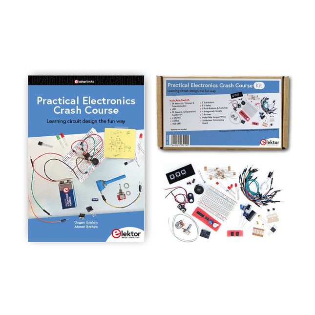
Elektor Bundles Practical Electronics Crash Course (Bundle)
Getting started in electronics is not as difficult as you may think. With this bundle (book + kit of parts), you can explore and learn the most important electrical and electronics engineering concepts in a fun way by doing various experiments. You will learn electronics practically without getting into complex technical jargon and long calculations. As a result, you will be creating your own projects soon. This kit contains the components required to build most of the detailed examples of the book on a breadboard and try them out for real. The kit can, of course, also be used without the book for building other circuits and doing your own experiments. Kit contents 1x 39 Ω, 1 W resistor 1x 47 Ω resistor 1x 180 Ω resistor 1x 330 Ω resistor 3x 1 kΩ resistor 1x 2.2 kΩ resistor 1x 3.9 kΩ resistor 1x 6.8 kΩ resistor 1x 10 kΩ resistor 1x 15 kΩ resistor 1x 22 kΩ resistor 1x 33 kΩ resistor 1x 47 kΩ resistor 1x 56 kΩ resistor 1x 82 kΩ resistor 1x 120 kΩ resistor 1x 680 kΩ resistor 2x 100 kΩ resistor 1x 10 kΩ trimmer 1x 10 kΩ linear potentiometer 1x 100 kΩ linear potentiometer 1x LDR 1x 1 nF ceramic capacitor 2x 10 nF ceramic capacitor 1x 100 nF ceramic capacitor 1x 1 µF, 25 V aluminium electrolytic capacitor 2x 10 µF, 25 V aluminium electrolytic capacitor 1x 100 µF, 25 V aluminium electrolytic capacitor 1x 470 µF, 25 V aluminium electrolytic capacitor 1x 1000 µF, 25 V aluminium electrolytic capacitor 1x RGB LED, Common-Cathode (CC) 1x 1N4148 small signal diode 1x 1N4733A 5.1 V, 1 W Zener diode 3x LED, red 2x BC337 NPN transistor 1x IRFZ44N N-channel MOSFET 2x NE555 timer 1x LM393 comparator 1x 74HCT08 quad AND gate 3x Tactile switch 2x SPDT switch 1x Relay, SPDT, 9 VDC 1x Active buzzer 1x Passive buzzer 50 cm Solid wire, 16 AWG, unjacketed 2x PP3 9 V battery clip 1x Breadboard 20x Jumper wire This bundle contains: Practical Electronics Crash Course Kit (valued at: €45) Book: Practical Electronics Crash Course (normal price: €45)
$79.79$62.41Best Price
-
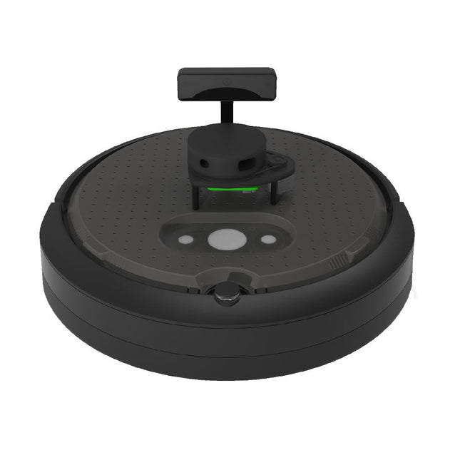
Clearpath Robotics Clearpath Robotics TurtleBot 4 Lite
TurtleBot 4 is the next-generation of the world’s most popular open source robotics platform for education and research, offering better computing power, better sensors and a world class user experience at an affordable price point.TurtleBot 4 Lite is equipped with an iRobot Create 3 mobile base, a powerful Raspberry Pi 4 running ROS 2, OAK-D spatial AI stereo camera, 2D LiDAR and more. All components have been seamlessly integrated to deliver an out-of-the-box development and learning platform.Specifications Base platform iRobot Create 3 Wheels (Diameter) 72 mm Ground Clearance 4.5 mm On-board Computer Raspberry Pi 4 (4 GB) Maximum linear velocity 0.31 m/s in safe mode0.46 m/s without safe mode Maximum angular velocity 1.90 rad/s Maximum payload 9 kg Operation time 2h 30m – 4h depending on load Charging time 2h 30m Lidar RPLIDAR A1M8 Camera OAK-D-Lite User Power VBAT @1.9 A5 V @ Low current3.3 V @ Low current USB Expansion 2x USB 2.0 (Type A)2x USB 3.0 (Type A) Programmable LEDs Create 3 Lightring Buttons and Switches 2x Create 3 User buttons1x Create 3 Power Button Battery 26 Wh Lithium Ion (14.4 V nominal) Charging Dock Included Size (L x W x H) 342 x 339 x 192 mm Weight 3.3 kg DownloadsUser Manual
$1,501.79
Best Price
-

FNIRSI FNIRSI TMP-610S (3-in-1) Multimeter (60,000 Counts) + Oscilloscope + Signal Generator
The FNIRSI TMP-610S is a compact 3-in-1 test instrument combining a True RMS multimeter, 10 MHz oscilloscope, and 50 kHz DDS signal generator. It is designed for electronics troubleshooting, circuit testing, and development in the lab or on the go. The multimeter offers 60,000-count resolution and supports voltage, current, resistance, capacitance, frequency, temperature, diode, and continuity measurements. The integrated oscilloscope provides real-time waveform analysis at up to 48 MSa/s, while the signal generator supports 13 waveform types with adjustable frequency, amplitude, and duty cycle. A 3.5-inch IPS touchscreen, smart auto-scan, Bluetooth connectivity for DMM functions, waveform storage, USB export, and a 3,000 mAh rechargeable battery make the TMP-610S a versatile all-in-one tool for electronics professionals and enthusiasts. Features 3-in-1 Design: DMM + Oscilloscope + Signal Generator 60,000-Count True RMS High-Precision Measurement 10 MHz Oscilloscope with 48 MSa/s Sampling Rate Bluetooth App Sync (Multimeter Function Only) 3.5-inch Smart Touchscreen with Multiple Display Modes 50 kHz DDS Signal Generator with 13 Waveforms Built-in Fuse for Easy Replacement Specifications Multimeter Function Range Accuracy DC voltage 600mV/6V/60V/600V/1000V ±(0.03%+5d) AC voltage 600mV/6V/60V /600V/750V ±(0.3%+15d) DC current 600uA/6000uA/60mA/600mA ±(0.15%+5d) 6A/10A ±(0.2%+5d) AC current 600uA/6000uA/60mA/600mA ±(0.5%+15d) 6A/10A ±(0.75%+15d) Resistance 600Ω/6KΩ/60KΩ/600KΩ/6MΩ ±(0.1%+5d) 60MΩ ±(0.2%+10d) Capacitance 60nF/600nF/6uF/60uF ±(2.5%+30d) 600uF/6mF/60mF ±(3.5%+30d Frequency 10 Hz~60 MHz ±(0.01%+5d) Temperature -40℃~1000℃ ±(1.0%+5℃) Continuity 0Ω~1KΩ ±(0.2%+5d) Diode 0V~3.0V, 0Ω~1 Ω ±(1%+5d) AC frequency response 10KHz / Oscilloscope Real-time Sampling Rate 48 MSa/s Analog Bandwidth 10 MHz Input Impedance 1MΩ Coupling Mode AC/DC Test Voltage Range 1:1 Probe - 80Vpp (±40V) 10:1 Probe - 800Vpp (±400V) Vertical Sensitivity 10mV/div~10V/div Vertical Displacement Adjustable with indication Horizontal Time Base Range 50 ns ~ 20 s Trigger Mode Auto, Normal, Single Trigger Type Rising, Falling, 50% Trigger Level Adjustable with indication Measurement Parameters Freq, Period, +Duty, ‒Duty, +Width, ‒Width, Max, Min, P‒P, Amp, RMS, Avg Persistence Off / 500ms / 1s / ∞ Cursor Measurement Yes Waveform Screenshot Saving Yes Signal Generator Output Waveform Supports 13 waveform types Frequency 0~50kHz Amplitude 0.0V~3.0V Duty Cycle 0~100%, adjustable for Square and Sawtooth waves Included 1x FNIRSI TMP-610S Multimeter + Oscilloscope + Signal Generator 1x P6100 Probe 1x Adapter 2x Alligator Clips 2x Multimeter Probes Probe Accessories 1x Storage Bag 1x USB-C Cable 1x Manual Downloads Manual
$132.72
Best Price
-

Andonstar Andonstar ADSM302 5" HDMI Digital Microscope
The Andonstar ADSM302 is a versatile digital microscope with an integrated 5-inch LCD display and HDMI output for crystal-clear views in Full HD (1080p). With a 3-megapixel sensor, up to ~560x magnification, and two adjustable LED lights, it reveals the finest details – ideal for PCB inspections, soldering work, jewelry or insect analysis. Features 5" adjustable LCD monitor with adjustable tilt angle High resolution video & photo capture Wide table with comfortable headroom Heavy-weight stable metal stand Tall lifting stand (26 cm) Smooth adjustment wheels for focus and height Buttons on the monitor + remote control AV, USB, HDMI outputs SD card storage <32 GB Specifications Image sensor 3 Megapixels HD Sensor Video output 1080p Full HD (via HDMI)720p (via PC) Video format Real time play via HDMI w/o recordingMJPEG recording via PC/Mac Software Magnification Up to 560 times (HDMI monitor 22") Photo resolution 12M (see pixel formats in following table) Photo format JPEG Focus range 5 to 22 cm Frame rate Up to 30 f/s under 600 Lux Brightness Video-output interface HDMI/AV Storage microSD card, up to 32 GB PC support Windows XP/7/8/10PC software with measurementMacOS successfully tested under OSX with OBSsee video below Power source 5 V DC Light source 2x LED with the stand Screen size 5 inch (12.7 cm) Stand size 20 x 12 x 26.5 cm Resolution Captured Photos 4032 x 3024 3648 x 2736 3264 x 2448 2592 x 1944 2048 x 1536 640 x 480 1920 x 1080 1280 x 960 1280 x 720* Videos 1920 x 1080 640 x 480* * (USB with software) Included 1x Andonstar ADSM302 digital microscope 1x Metal stand with 2 LEDs 1x USB cable 1x HDMI cable 1x Adapter 1x AI remote 1x Instructions Downloads Manual Software
$176.17
-
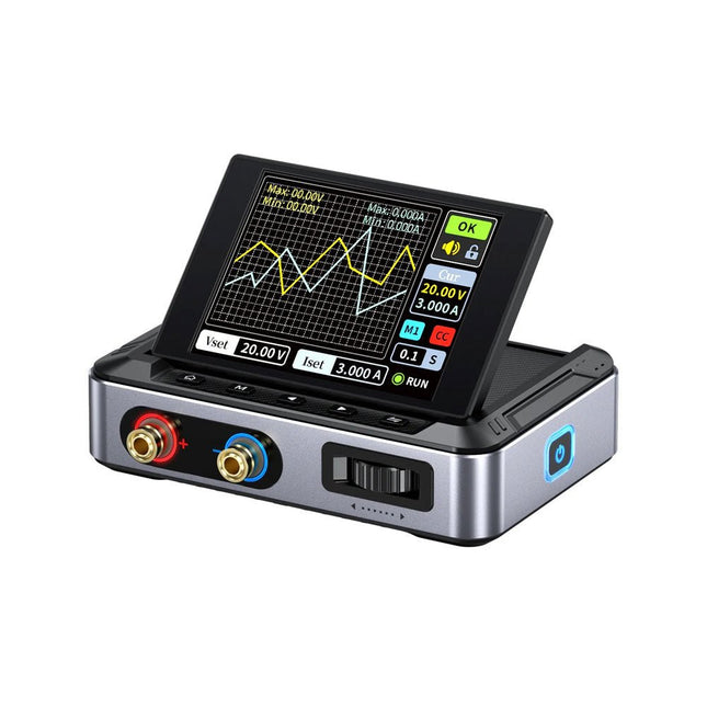
FNIRSI FNIRSI DPS150 DC Power Supply (150 W)
The FNIRSI DPS150 is a high-performance adjustable DC power supply that features a USB-C input interface and multiple power supply modes, allowing precise adjustment of output voltage (0-30 V) and current (0-5 A). It provides efficient, low-consumption, and stable output, equipped with multiple safety protection functions including overvoltage, overcurrent, overload, overheating, and reverse connection. It can be flexibly applied to serial connection of multiple devices, with rich and user-friendly display and operation, compact and portable design, meeting various application needs. Features 30 V, 5 A, 150 W variable DC power with 0.01 V, 0.001 A precision, CC/CV modes, and <20 mV ripple to protect sensitive electronics. Supports PC, QC, and DC inputs with programmable outputs and 6 preset voltage/current settings. Compatible with 4 mm banana plugs, U-shaped terminals, and copper wires for various equipment. 8 safety mechanisms including overvoltage, current, short circuit, and overheating protection. 2.8-inch HD IPS screen with 90° flip, numerical and curve displays for easy monitoring. Small, space-saving design for use in labs, repairs, and DIY projects. Specifications Input Voltage 5~32 V DC Input Current 100 mA-5 A Output Voltage 0-30 V Output Current 0~5 A Output Power 0-150 W Input Way PD fast charger QC fast charger Power bank DC power adapters Operating Environment 0-40°C Load Regulation 0.49% Full Load Efficiency 96.30% Display 2.8 inch (320 x 240) Dimensions 106 x 76 x 28 mm Weight 178 g Included 1x DPS150 Power Supply 2x Alligator clip wires (black & red) 1x Micro USB cable 1x Manual Downloads Manual Firmware V0.0.1
$52.93
-

Elektor Labs Elektor Low-Noise Lab Power Supply
The Elektor Low-Noise Lab Power Supply is a fully analogue, adjustable, medium-power symmetrical bench supply that contains no switching or digital components. It provides an output voltage adjustable between 0 V and ±22 V, and an output current adjustable from 0 A to 1 A. Because it avoids any form of switching circuitry, the design delivers extremely low noise. To display both output voltages and currents, four miniature moving-coil panel meters are used. Most modern laboratory power supplies and AC adapters employ switch-mode techniques. Even the best examples inevitably exhibit high-frequency ripple and other switching artefacts on their output, which can interfere with the testing of sensitive analogue circuits and disturb low-level measurements. To overcome this, the concept here is a completely analogue power supply. Although less efficient than its switch-mode counterparts, the reduced efficiency is of little importance for test-bench use and ensures cleaner, more reliable measurement results. Because many analogue circuits require a symmetrical supply, this design delivers positive and negative output voltages of equal magnitude. A small amount of adjustment is available to compensate for any imbalance. Naturally, a variable current-limit function is also included. The kit includes the components required to build the power supply, except for the transformers. Specifications Output Voltage 0…+22 V, 0, −22 V Output Current 0…+1 A, 0…−1 A Noise −85 dBV, (at 0.95 A/20 V, B = 22 kHz) −84 dBV (at 0.95 A/20 V, B > 500 kHz) Ripple 50 µVRMS (at 950 mA/20 V, B = 22 kHz, mainly 100 Hz component) Included 3x PCBs: Regulator (PCB-1), Mains Filter (PCB-2) and Transformer (PCB-3) All the components except the AC transformers 4x moving-coil meters Additional parts for wiring (wires, banana sockets, IEC Power entry module, etc.) Not included The three AC transformers An enclosure Parts List For the Regulator PCB (240386-1) Resistors (250 mW, 1%) R1 = 12 Ω R2, R8, R37, R62 = 1 MΩ R3, R7, R10, R13, R17, R20, R22, R30, R35, R42, R45, R47, R55, R60 = 100 Ω, 600 mW R4, R5 = 4.7 kΩ R6 = 100 kΩ R9, R12, R14, R36, R38, R39, R61, R63, R66, R72, R78, R79 = 10.0 kΩ, 600 mW R11 = 9.76 kΩ, 600 mW R15, R40 = 44.2 kΩ, 600 mW R16, R41, R77 = 1 kΩ R18, R43 = 1.5 kΩ, 1 W, 5% R19, R44 = 470 Ω, 1 W, 5% R21, R46 = 330 Ω, 600 mW R23, R24, R48, R49 = 1.0 Ω, 1 W R25, R50 = 1 kΩ, 1 W, 5% R26, R28, R51, R53 = 1.000 kΩ 0.1%, 15 ppm/C R27, R29, R52, R54 = 10.00 kΩ 0.1%, 15 ppm/C R31, R56 = 1.2 kΩ, 1 W, 5% R32, R57 = 47 kΩ R33, R58 = 270 Ω R34, R59 = 27 kΩ R64, R69 = 12.0 kΩ R65 = 3.0 kΩ, 600 mW R67, R80 = 470 Ω, 600 mW R68, R70 = 6.8 kΩ, 600 mW R71 = 30.0 kΩ,, 600 mW R73, R74, R75, R76 = 10 MΩ P1, P2, P3 = 10 kΩ, 200 mW, 20%, potentiometer, 1 turns, single, lin., panel mount P4, P5 = 500 Ω, 500 mW, 10%, trimmer, 25 turns, 3296Y-1-501LF Bourns P6, P7 = 10 kΩ, 500 mW, 10%, trimmer, 25 turns, 3296Y-1-501LF Bourns Capacitors C1 = 100 nF, 50 V, 10%, ceramic X7R, LS 5 mm C2, C3, C6, C7, C30 = 10 µF, 63V, 20%, LS 2.5 mm, 3000hours@105°C C4, C5, C8, C9, C13, C14, C18, C19, C23, C24, C28, C29, C31, C32, C38, C39 = 100 nF, 250 V, 10%, PET, LS 7.5 mm C10, C20 = 47 nF, 100 V, 5%, PET, LS 5 mm C11, C21 = 10 nF, 100 V, 5%, PET, LS 5 mm C12, C22 = 220 µF, 35 V, 20%, 0.024 Ω, LS2.5/3.5 mm, Ir 3.4 A, 2000hours@125°C, polymer C15, C25 = 120 µF, 50 V, 20%, ESR 0.02 Ω, Diam. 10 mm max., LS 5 mm C16, C26 = 15 nF, 100 V, 5%, PET, LS 5 mm C17, C27 = 47 nF, 100 V, 5%, PET, LS 5 mm C33, C34 = 22 µF, 50 V, 20%, LS 2 mm, 10000 hours @ 105°C C35, C36, C44, C45 = 1 µF, 100 V, 10%, LS 5 mm, ceramic X7R C37 = 100 uF, 50 V, 20%. LS 3.5 mm C40, C41, C42, C43, C46, C47, C48, C49 = 1000 µF, 50 V, 20%, LS 5/7.5 mm, Ir 3.32 A, 10000hours@105°C, D 16 mm C50, C51, C52, C53 = 47 nF, 100 V, 10%, ceramic X7R, LS 5 mm Inductors L1, L2 = 4.7 µH, 3.2 A, 0.033 Ω, LS 5 mm, RLB0914-4R7ML Bourns L3 = Commom mode choke, 14.5 mH, 3 A, SSRH24NH-30145 Kemet Semiconductors D1, D2, D3, D4, D5, D9, D10, D11, D15 = BAT85, DO-34 D6, D7, D12, D13 = SR560, DO-201AD D8, D14, D16 = 1N4148, DO-35 D17 = Zenerdiode, 5.6 V, 0.5 W, DO-41 D18, D19 = 1N4004, DO-41 D20, D21 D22, D23 = V30100CI-M3/P, dual common cathode, TO-220 D24 = Zener diode, 30 V, 1 W, DO-41 LED1, LED2 = LED, red, T-1 (3 mm) LED3, LED4 = LED, green, T-1 (3 mm) TVS1, TVS2 = BZW50-33B, R6 T1, T2, T4 = BC337.25, TO-92 T3 = NJW0302G, TO-3P T5, T6, T8 = BC327.25, TO-92 T7 = NJW0281G, TO-3P T9 = BD139, TO-126 (SOT-32) IC1 = LM334Z, TO-92 IC2 = LM4040AIZ-5.0/NOPB, TO-92 (TO-226AA-3) IC3, IC4 = OPA2992IDR, SOIC-8 IC5, IC6 = OPA4992IDR, SOIC-14 IC7 = OPA992IDBVR, SOT-23-5 IC8 = LM339N, DIP-14 IC9 = LM317, TO-220 IC10 = LM337, TO-220 Others F1, F2 = 5×20 mm fuse, 1.6 A, fast acting HS1, HS2 = Heatsink MC33271 (for T3/T7), 2.7°C/W, PCB mount, height 63.5 mm K1, K4 = 3-way screw terminal block, LS 3.5 mm, max. 1.5 mm² K2, K3 = 3-way screw terminal block, LS 3.5 mm, max. 1 mm² M1, M3 = Moving coil meter, Range 30 V, type 91C4, 45×45 mm M2, M4 = Moving coil meter, Range 1 A, type 91C4, 45×45 mm² RE1 = Relay DPDT,5V, UA2-5NU Miscellaneous 3× 3-way screw terminal block, LS 3.5 mm, max. 1 mm² (for P1, P2, P3) 4× Pin header, 1×2, vertical, pitch 2.54 mm (for LED1, LED2, LED3, LED4) 4× Pin socket, 1×2, vertical. pitch 2.54 mm (for LED1, LED2, LED3, LED4) 2× Heatsink FK222SA220, 20°C/W, PCB mount (for IC9 & IC10) 2× Mica thermal pad for TO-220, 12×18×0.05 mm (for IC9 & IC10) 2× Insulating bushing IB 6, TO-220 (for IC9 & IC10) 2× Ceramic thermal pad, 23×20×2 mm (for T3 & T7) 2× PCB Fuse Holder, for 5×20 mm fuse, 10 A (for F1, F2) 2× Cover for PCB Fuse Holder, transparent (for F1, F2) 2× 2-way screw terminal block, LS 3.5 mm, max. 1 mm² (for M1 & M3) 2× 2-way screw terminal block, LS 3.5 mm, max. 1.5 mm² (for M2 & M4) 8× M3 solder lug, thickness 0.35 mm (for M1…M4) M4 solder lug, thickness 0.35 mm (to connect 4 mm banana connectors) Screened cable, 1 pair, 2×24 AWG/0.22 mm², 1 m (for P1, P2 & P3) IC socket, DIP, 14 contacts (for IC8) M3 washer, plain, steel M3 screw, 16 mm, steel, pan head M3 nut M3 spring washer 50 mm M3 standoff, steel, male-female 12 mm M3 standoff, steel, male-female 10 mm M3 standoff, steel, male-female M3 screw, 8 mm, steel, pan head For the Mains Fiter PCB (240386-2) Resistor R1 = 220 kΩ, 1 W, 500 V, 5% Capacitors C1, C2 = 470 nF, 305 VAC, Class X2, 11 × 27 mm max., LS 15/22.5 mm C3, C4, C5, C6 = 2.2 nF, 300 VAC, Class Y2, 13 × 4 mm, LS 10 mm, PP Inductors L1, L2 = Common-mode choke, 6.8 mH, 1.7 A, TDK B82732R2172B030 Semiconductor MOV1 = TVS varistor, 300 VAC, S14K300 (230 VAC, B72214S0301K101) and SK14K150 (150 VAC, B72214S0151K101) Others K1, K2 = 3-way screw terminal block, LS 7.62 mm F1 = Time-delay fuse, 0.5 A (230 VAC) or 1 A (115 VAC) Miscellaneous 1× Fuse holder, 5×20 mm, 10 A, 500 VAC 1× Transparent fuse cover 4× 10 mm M3 standoff, steel, male–female 4× M3 screw, 8 mm, steel, pan head 4× M3 nut For the Transformer PCB (240386-3) Resistors R1, R2 = 2.7 kΩ, 600 mW, 1% R3 = 10.0 kΩ, 600 mW, 1% Capacitor C1 = 220 µF, 50 V, 20%, Ø10 mm, LS 5 mm, 4000 h @ 105°C Transformers (not included in this kit!) TR1, TR2, TR3 = 2×7 V, 25 VA, PCB-mounted toroid, 70060K Talema Semiconductors D1–D4 = 1N4148, DO-35 D5, D6 = 1N4004, DO-41 D7 = Zener 5.6 V, 1.3 W, DO-41 LED1 = LED, red, T-1 (3 mm) IC1, IC2 = MOC8021M, CTR ≥ 1000%, DIP-6 Others F1, F2, F3 = 160 mA time-delay fuse (230 VAC) or 315 mA time-delay fuse (115 VAC) K1 = 2-way screw terminal block, LS 7.62 mm K2 = 3-way screw terminal block, LS 3.5 mm, max 1.5 mm² K3, K4 = 3-way screw terminal block, LS 3.5 mm, max 1 mm² RE1, RE2 = Relay DPDT, 5 A/250 VAC / 24 VDC Miscellaneaous 1× Pin header 1×2, pitch 2.54 mm + matching socket for LED1 3× Fuse holder 5 × 20 mm, 10 A, 500 VAC + transparent cover 3× M4 screw, 8 mm, pan head + washer for TR1-TR3 8× M3 screw, 8 mm, pan head + nut + washer 8× 10 mm M3 standoff, steel, male–female 2× IC socket, DIP-6 for IC1 & IC2 Additional Parts 1 m red insulated wire, stranded, 1.5 mm² 0.5 m blue insulated wire, stranded, 1.5 mm² 0.5 m black insulated wire, stranded, 1.5 mm², 0.5 m 2 m red insulated wire, stranded, D 0.56 mm (0.25 mm²) 2 m black insulated wire, stranded, D 0.56 mm (0.25 mm²) 0.5 m Multicore Cable, Flexible, 3 Core, 0.75 mm² (24 x 0.2 mm) Red banana socket Black banana socket Blue banana socket Green banana socket IEC Power Entry Module with switch, IEC C14 3 crimp terminals, FASTON, 4.75 x 0.81 mm 3 knobs Links Elektor Labs JumpStarter Page Article (Part 1) Article (Part 2)
$220.41
Best Price
-

Elektor Digital Starten met Internet of Things (E-book)
35 projecten met Raspberry Pi en wireless Arduino Internet of Things (alles aan het internet) is een trend die zich niet meer laat keren. We willen alles in huis met onze mobiel of tablet doen, van Facebook tot TV kijken, van lichten bedienen tot de temperatuur in de gaten houden. In dit boek laten we in 35 leuke en handige projecten zien hoe u op eenvoudige wijze zelf een Internet of Things systeem kunt aanleggen. We gaan in op de hardware (de perfecte combinatie van Raspberry Pi en Arduino) en de software om bediening via internet mogelijk te maken. We maken gebruik van Wi-Fi en radioverbindingen zodat er geen kabels dwars door uw huis hoeven. Wanneer u deze projecten maakt heeft u een compleet Internet of Things systeem waarmee u van alles in uw huis kunt bedienen en bekijken. Bijvoorbeeld of er post in de brievenbus ligt en of de auto in de garage staat. U kunt op vanaf de bank het licht aandoen en het alarm bedienen. Door de heldere uitleg kunt u de projecten eenvoudig aanpassen om bijvoorbeeld uw koffiezetautomaat of tv op afstand aan te zetten. Via de index vindt u gemakkelijk creatieve projecten die als voorbeeld kunnen dienen, zodat u zelfstandig alles met het internet kunt verbinden.
$30.94
Members: $27.85
-

Elektor Digital Édition spéciale : Les capteurs météorologiques et environnementaux (PDF)
Construisez votre station météo idéale ou explorez les données environnementales avec le monde entier. Avec de nombreux projets pratiques pour Arduino, Raspberry Pi, NodeMCU, ESP32 et autres cartes de développement. Les stations météo jouissent d’une grande popularité depuis des décennies. Tous les magazines d’électronique, qu’ils soient récents ou non, ont publié et publient régulièrement des articles sur la construction d’une station météo. Au fil des années, elles sont devenues de plus en plus sophistiquées et peuvent aujourd’hui être entièrement intégrées dans la maison intelligente. Ceci implique toutefois souvent une fidélité à un fabricant de produits de marque (coûteux) pour tous les composants. Cependant, avec votre propre station météo, vous pouvez facilement suivre le rythme et même capturer des relevés que les appareils commerciaux ne peuvent pas réaliser. Le plaisir ne manque pas : vous développerez de manière ludique vos connaissances en électronique, en cartes de développement de microcontrôleurs modernes et en langages de programmation. Pour moins de dix euros, vous pouvez collecter des données environnementales initiales et étendre votre système au fur et à mesure que votre intérêt grandit. Dans ce numéro Sur la route du vent et de la météo Écran météo OpenWeatherMap à affichage fluorescent Les composés organiques volatils dans l‘air que nous respirons Travailler avec les capteurs MQ : mesurer le monoxyde de carbone Détecteur de CO2 avec connexion IdO vers ThingSpeak Un arrosage automatique pour vos plantes Un climat intérieur sain : la température et l‘humidité de l‘air sont importants Thermomètre avec tubes Nixie Une maison météo rétro pour toute la famille Mesurez la pression atmosphérique et la température avec précision Un détecteur de coups de soleil Capteur maison pour la durée d‘ensoleillement Le smartphone l‘indique : brouillard ou bonne visibilité ? Détecter les tremblements de terre Les niveaux des cours d‘eau et des réservoirs Évaluer la valeur du pH de l’eau Détecter les rayonnements radioactifs Avec le GPS, vous savez où se trouve votre capteur Enregistrer les fichiers journaux avec horodatage sur des cartes SD LoRaWAN, The Things Network et ThingSpeak Exploiter la passerelle LoRaWAN pour le TTN Affichage géant à led avec prévisions météo
$11.83
Members: $10.65
-

Elektor Publishing Intelligente Sensoren in Embedded-Systemen
Vom Messwert zur stabilen Entscheidung Wie wird aus einem einfachen Mikrocontroller ein intelligentes System, das Sensorwerte erfasst, verarbeitet und sinnvoll darauf reagiert? Dieses Buch zeigt es Ihnen Schritt für Schritt – verständlich, praxisnah und ohne unnötige Vorkenntnisse. Sie beginnen mit den Grundlagen der digitalen und analogen Ein- und Ausgänge. Anschließend lernen Sie, wie Sensorwerte gelesen, geglättet und zuverlässig bewertet werden. Anschauliche Beispiele erklären, warum einzelne Messwerte oft täuschen können und wie Mittelwertbildung, Hysterese und einfache Entscheidungsregeln für stabile Ergebnisse sorgen. Nach und nach erweitern Sie Ihre Projekte um Displays, I²C-Kommunikation und mehrere vernetzte Mikrocontroller. So entstehen verteilte Systeme, in denen Raspberry Pi Pico und ATtiny-Controller Daten austauschen und gemeinsam Aufgaben übernehmen. Im fortgeschrittenen Teil erhalten Sie einen leicht verständlichen Einstieg in Merkmalsbildung, Datenvorverarbeitung, hybride Entscheidungsmodelle und TinyML-nahe Anwendungen. Dabei verbinden Sie klassische Regelungstechnik mit modernen datenbasierten Methoden. Alle Projekte werden von ausführlich kommentierten Programmen in C und MicroPython begleitet. Das Buch richtet sich an Einsteiger, Maker, Studierende und alle, die Embedded-Systeme von Grund auf verstehen möchten. Am Ende können Sie eigene Systeme entwickeln, die nicht nur messen, sondern Informationen auswerten, zuverlässige Entscheidungen treffen und gezielt reagieren.
$35.55
Best Price
-

Elektor Digital Elektor July/August 2024 (PDF)
Elektor GREEN and GOLD members can download their digital edition here. Not a member yet? Click here. Small Thermal Imaging CameraAn Arduino UNO-Based DIY Solution Project Update #3: ESP32-Based Energy MeterIntegration and Testing with Home Assistant 2024: An AI OdysseyEnhancing Object Detection: Integrating Refined Techniques Raspberry Pi Goes AINew Kit Incorporates M.2 HAT+ With AI Accelerator Weather Station SensorsWhich One Should You Choose? AI-Based Water Meter Reading (1)Get Your Old Meter Onto the IoT! A GSM AlarmHarnessing GSM Technology for Remote Garage Safety Low-Power Thread Devices Optimized and ScrutinizedLow Power … Low Effort? From Life’s ExperienceThe Gender Gap DIY Cloud ChamberMaking Invisible Radiation Visible SparkFun Thing Plus MatterA Versatile Matter-Based IoT Development Board IoT RetrofittingMaking RS-232 Devices Fit for Industry 4.0 Enabling IoT with 8-Bit MCUs Technology Drives SustainabilityAdvances Lead to More Efficient Use of Energy in Many Applications AWS for Arduino and Co. (1)Using AWS IoT ExpressLink in Real Life Airflow Detector Using Arduino OnlyNo External Sensors Needed! Water Leak DetectorConnected to Arduino Cloud CrystalsPeculiar Parts, the Series Universal Garden LoggerA Step Towards AI Gardening Analog 1 kHz GeneratorSine Waves with Low Distortion Miletus: Using Web Apps OfflineSystem and Device Access Included! From 4G to 5GIs It Such an Easy Step? Starting Out in Electronics……Balances Out
$8.19
-

Elektor Digital Elektor Mars/Avril 2026 (PDF) FR
Le téléchargement intégral de ce numéro est disponible pour nos membres GOLD et GREEN sur le site Elektor Magazine ! Pas encore membre ? Cliquez ici. programmation PIO sur le Raspberry Pi PicoNeuf instructions, de multiples possibilités l'IA en ligne de commandeDéveloppement, compilation et validation de projets embarqués depuis le terminal le Scrutiny DebuggerDéboguer, visualiser et tester du code C/C++ embarqué carte breakout Sigfox (1)Développement d’une BoB radio alimentation à faible bruit (2)Construction, assemblage et mise en œuvre pratique générateur de signaux simple basé sur le RP2040Signaux analogiques et numériques à la découverte du futur de la domotique avec Matter et l’IA EdgeLes dernières versions de Matter et l’essor de l’IA en périphérie de réseau (edge) donnent-ils enfin aux ingénieurs les outils nécessaires pour construire les maisons intelligentes et parfaitement intégrées promises aux utilisateurs ? capteurs de pression différentielleLa maintenance prédictive appliquée aux systèmes CVC la sécurité dès la conceptionPrincipes d’ingénierie pour limiter les défaillances la sécurité des systèmes embarqués n’est plus une option la CRA et la PQC redéfinissent les priorités de la sécurité embarquéePourquoi même les petites entreprises IoT et industrielles doivent prévoir une mise à niveau embedded world 2026Entretien avec Benedikt Weyerer, directeur d’embedded world prise en main du bus I3CUtilisation de matériel de ST et Microchip le projet BLEnkyPrototypage rapide d’applications Bluetooth Low Energy modulation de largeur d’impulsionDu thermostat tout ou rien à un signal analogique continu filtré audiotroniqueDes circuits audio agréables à l’écoute, à réaliser soi-même sur le vifLisez donc le manuel ! carte émetteur-récepteur audio ESP32 (4)Réglage des horloges et une option filaire 2026 : une odyssée de l’IAConséquences du vibe coding charge CC symétriqueCharge CC symétrique, statique ou dynamique comptage de visages avec MaixCAMUne méthode simple pour estimer la taille d’un public
$11.83
-

FNIRSI FNIRSI DLA-16/32 Plus Logic Analyzer (16/32 Channels)
The FNIRSI DLA Series combines high-performance USB 3.0 logic analysis with flexible multi-channel signal capture for debugging and analyzing digital circuits and embedded systems. The series is available in two versions: the DLA-16 Plus with 16 digital channels and the DLA-32 Plus with 32 digital channels. Both models offer sampling rates of up to 1 GSa/s, 4 Gbit of onboard memory, and support for 120+ protocol decoders. With Buffer, Stream, and Roll acquisition modes, they are suitable for both high-speed signal analysis and long-term monitoring. Choose the DLA-16 Plus for higher sampling rates when using all channels, or the DLA-32 Plus when you need more channels and advanced serial and parallel triggering. Features Available with 16 or 32 digital input channels Up to 1 GSa/s sampling rate DLA-16 Plus: up to 500 MSa/s with all 16 channels DLA-32 Plus: up to 250 MSa/s with all 32 channels 4 Gbit onboard memory High-speed USB 3.0 interface Acquisition modes: Buffer, Stream, and Roll Support for 120+ protocol decoders Advanced triggering options 4 PWM outputs with 1 Hz–20 MHz frequency range CSV and BIN data export Specifications DLA-16 Plus DLA-32 Plus Digital Channels 16 32 Max. Sampling Rate 1 GSa/s Sampling Rate (1 Channel) 1 GSa/s Sampling Rate (8 Channels) 1 GSa/s Max. Buffer Sampling 16 CH @ 500 MSa/s 32 CH @ 250 MSa/s Max. Stream Sampling 16 CH @ 125 MSa/s 32 CH @ 50 MSa/s Hardware Memory 4 Gbit Interface USB 3.0 / USB-C Max. USB Transfer Rate 5 Gbit/s Acquisition Modes Buffer / Stream / Roll Protocol Decoders 120+ Custom Protocol Support Yes Trigger Modes Rising Edge, Falling Edge, High, Low, Any Edge Advanced Trigger Standard Triggering Serial and Parallel Parallel Trigger Stages – Up to 16 PWM Outputs 4 PWM Output Voltage 3.3 V PWM Frequency 1 Hz–20 MHz Data Export CSV, BIN Dimensions 90 x 81 x 11.5 mm Included 1x FNIRSI DLA-16/32 Plus Logic Analyzer 4 Sets x 5 Shielded Cables 18x Mini IC Test Hooks (High Configuration Version) 1x USB 3.0 Data Cable 10x IC Test Hooks 1x Transparent Storage Case for Test Hooks 1x Storage Bag 1x Manual Downloads Manual Software for Windows Software for macOS (Apple Silicon) Software for macOS (Intel)


