
Search results for "official OR raspberry OR pi OR 5 OR desktop OR kit OR eu"
-
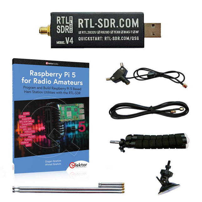
Elektor Bundles Raspberry Pi 5 RTL-SDR V4 (Bundle)
Program and build Raspberry Pi based ham station utilities, tools, and instruments The improved RTL-SDR V4 allows you to receive radio signals between 500 kHz and 1.75 GHz from stations utilizing different bands including MW/SW/LW broadcast, ham radio, utility, air traffic control, PMR, SRD, ISM, CB, weather satellite, and radio astronomy. The book Raspberry Pi 5 for Radio Amateurs gives extensive coverage of deploying the RTL-SDR kit through the use of a Raspberry Pi 5. This bundle contains: RTL-SDR V4 (incl. Dipole Antenna Kit) (normal price: €75) Raspberry Pi 5 for Radio Amateurs (normal price: €40) RTL-SDR V4 (Software Defined Radio) with Dipole Antenna Kit RTL-SDR is an affordable dongle that can be used as a computer-based radio scanner for receiving live radio signals between 500 kHz and 1.75 GHz in your area. The RTL-SDR V4 offers several improvements over generic brands including use of the R828D tuner chip, triplexed input filter, notch filter, improved component tolerances, a 1 PPM temperature compensated oscillator (TCXO), SMA F connector, aluminium case with passive cooling, bias tee circuit, improved power supply, and a built in HF upconverter. RTL-SDR V4 comes with the portable dipole antenna kit. It is great for beginners as it allows for terrestrial and satellite reception and easy to mount outdoors and designed for portable and temporary outside usage. Features Improved HF reception: V4 now uses a built-in upconverter instead of using a direct sampling circuit. This means no more Nyquist folding of signals around 14.4 MHz, improved sensitivity, and adjustable gain on HF. Like the V3, the lower tuning range remains at 500 kHz and very strong reception may still require front end attenuation/filtering. Improved filtering: The V4 makes use of the R828D tuner chip, which has three inputs. The SMA input has been triplexed input into 3 bands: HF, VHF and UHF. This provides some isolation between the 3 bands, meaning out of band interference from strong broadcast stations is less likely to cause desensitization or imaging. Improved filtering x2: In addition to the triplexing, the open drain pin on the R828D can be also used, which allows to add simple notch filters for common interference bands such as broadcast AM, broadcast FM and the DAB bands. These only attenuate by a few dB, but may still help. Improved phase noise on strong signals: Due to an improved power supply design, phase noise from power supply noise has been significantly reduced. Less heat: Another advantage of the improved power supply is low power consumption and less heat generation compared to the V3. Included 1x RTL-SDR V4 dongle (R828D RTL2832U 1PPM TCXO SMA) 2x 23 cm to 1 m telescopic antenna 2x 5 cm to 13 cm telescopic antenna 1x Dipole antenna base with 60 cm RG174 1x 3 m RG174 extension cable 1x Flexible tripod mount 1x Suction cup mount Downloads Datasheet User Guide Quick Start Guide SDR# User Guide Dipole Antenna Guide Book: Raspberry Pi 5 for Radio Amateurs The RTL-SDR devices (V3 and V4) have gained popularity among radio amateurs because of their very low cost and rich features. A basic system may consist of a USB based RTL-SDR device (dongle) with a suitable antenna, a Raspberry Pi 5 computer, a USB based external audio input-output adapter, and software installed on the Raspberry Pi 5 computer. With such a modest setup, it is possible to receive signals from around 24 MHz to over 1.7 GHz. This book is aimed at amateur radio enthusiasts and electronic engineering students, as well as at anyone interested in learning to use the Raspberry Pi 5 to build electronic projects. The book is suitable for both beginners through experienced readers. Some knowledge of the Python programming language is required to understand and eventually modify the projects given in the book. A block diagram, a circuit diagram, and a complete Python program listing is given for each project, alongside a comprehensive description. The following popular RTL-SDR programs are discussed in detail, aided by step-by-step installation guides for practical use on a Raspberry Pi 5: SimpleFM GQRX SDR++ CubicSDR RTL-SDR Server Dump1090 FLDIGI Quick RTL_433 aldo xcwcp GPredict TWCLOCK CQRLOG klog Morse2Ascii PyQSO Welle.io Ham Clock CHIRP xastir qsstv flrig XyGrib FreeDV Qtel (EchoLink) XDX (DX-Cluster) WSJT-X The application of the Python programming language on the latest Raspberry Pi 5 platform precludes the use of the programs in the book from working on older versions of Raspberry Pi computers.
-

SunFounder SunFounder Kepler Kit (Ultimate Starter Kit for Raspberry Pi Pico W)
Your gateway to IoT and microcontroller programming With 450+ components and 117 online projects, this comprehensive kit ignites your creativity. The tutorials by Paul McWhorter make learning enjoyable for beginners and advanced users. This kit supports MicroPython, C/C++, and Piper Make, offering diverse programming options. Explore sensors, actuators, LEDs, and LCDs for endless project possibilities. From home automation to robotics, this kit empowers your tech journey. Features IoT Starter Kit for Beginners: This kit offers a rich IoT learning experience for beginners. With 450+ components, 117 projects, and expert-led video lessons, this kit makes learning microcontroller programming and IoT engaging and accessible. Expert-Guided Video Lessons: The kit includes 27 video tutorials by the renowned educator, Paul McWhorter. His engaging style simplifies complex concepts, ensuring an effective learning experience in microcontroller programming. Wide Range of Hardware: The kit includes a diverse array of components like sensors, actuators, LEDs, LCDs, and more, enabling you to experiment and create a variety of projects with the Raspberry Pi Pico W. Supports Multiple Languages: The kit offers versatility with support for three programming languages - MicroPython, C/C++, and Piper Make, providing a diverse programming learning experience. Dedicated Support: Benefit from our ongoing assistance, including a community forum and timely technical help for a seamless learning experience. Included Raspberry Pi Pico W Breadboard Jumper Wires Resistor Transistor Capacitor Diode Li-po Charger Module 74HC595 TA6586 – Motor Driver Chip LED RGB LED LED Bar Graph 7-segment Display 4-Digit 7-Segment Display LED Dot Matrix I²C LCD1602 WS2812 RGB 8 LEDs Strip Buzzer DC Motor Servo DC Water Pump Relay Button Micro Switch Slide Switch Potentiometer Infrared Receiver Joystick Module 4x4 Keypad MPR121 Module MFRC522 Module Photoresistor Thermistor Tilt Switch Reed Switch PIR Motion Sensor Module Water Level Sensor Module Ultrasonic Module DHT11 Humiture Sensor MPU6050 Module Documentation Online Tutorials in 3 languages (EN, DE and JP)
-

Elektor Bundles Mikrocontroller-Praxiskurs für Arduino-Einsteiger (Bundle)
Mit dem Elektor Arduino Nano Trainingsboard (MCCAB) eigene Projekte realisieren Der Mikrocontroller ist das wohl faszinierendste Teilgebiet der Elektronik, denn aufgrund der Vielzahl von Funktionen, die er auf seinem Chip vereinigt, ist er für den Entwickler ein universelles Multi-Tool zur Realisierung seiner Projekte. Praktisch jedes Gerät des täglichen Gebrauchs wird heute von einem Mikrocontroller gesteuert. Für einen elektronischen Laien blieb es aufgrund der Komplexität bisher allerdings ein Wunschtraum, eigene Ideen mit einem Mikrocontroller zu realisieren. Das Arduino-Konzept hat den Einsatz von Mikrocontrollern weitgehend vereinfacht, sodass jetzt auch Laien eigene Elektronik-Ideen mit einem Mikrocontroller verwirklichen können. Buch & Hardware im Bundle: 'Learning by Doing' Dieses im Bundle mitgelieferte Buch (im großen A4-Format) zeigt, wie man auch ohne große Erfahrung in Elektronik und Programmiersprachen eigene Projekte mit einem Mikrocontroller realisieren kann. Es ist ein Mikrocontroller-Praxiskurs für Einsteiger, denn nach einem Überblick über die Interna des Mikrocontrollers und einer Einführung in die Programmiersprache C liegt der Schwerpunkt des Kurses auf den praktischen Übungen. Der Leser eignet sich die erforderlichen Kenntnisse durch 'Learning by Doing' an: in dem umfangreichen Praxisteil mit 12 Projekten und 46 Übungen wird das im vorderen Teil des Buches Gelernte mit vielen Beispielen unterlegt. Die Übungen sind dabei so aufgebaut, dass der Bearbeiter eine Aufgabenstellung erhält, die er mit seinem im Theorieteil des Buches aufgebauten Wissen löst. Für jede Übung gibt es anschließend eine ausführlich erklärte und kommentierte Musterlösung, die dem Bearbeiter bei Problemen weiterhilft und die er mit seiner eigenen Lösung vergleichen kann. Arduino IDE In der Arduino IDE, einer Software-Entwicklungsumgebung, die kostenlos auf den eigenen PC heruntergeladen werden kann und die das gesamte Softwarepaket enthält, das für ein eigenes Mikrocontroller-Projekt benötigt wird, schreibt der Bearbeiter mit dem Editor der IDE seine Programme („Apps“) in der Programmiersprache C. Der in die Arduino IDE integrierte Compiler übersetzt sie in die Bits und Bytes, die der Mikrocontroller versteht und die dann über ein USB-Kabel in den Speicher des Mikrocontrollers auf dem Elektor Arduino Nano Trainingsboard (MCCAB) geladen werden. Externe Sensoren, Motoren oder Baugruppen abfragen oder steuern Das Elektor Arduino Nano Trainingsboard (MCCAB) enthält neben einem Mikrocontrollermodul Arduino Nano alle für die Übungen benötigten Bauteile wie Leuchtdioden, Schalter, Taster, akustische Signalgeber usw. Auch externe Sensoren, Motoren oder Baugruppen können mit diesem Mikrocontroller-Übungssystem abgefragt oder gesteuert werden. Technische Daten (Arduino Nano Trainingsboard MCCAB) Stromversorgung Über die USB-Verbindung des zur Erstellung der Programme sowieso angeschlossenen PCs oder ein externes Netzteil (nicht im Lieferumfang enthalten) Betriebsspannung +5 Vcc Eingangsspannung Alle Eingänge 0 V bis +5 V VX1 und VX2 +8 V bis +12 V (nur bei Verwendung eines externen Netzteils) Mikrocontrollermodul Arduino Nano Hardwareperipherie LCD 2x16 Zeichen Potenziometer P1 & P2 JP3: Auswahl der Betriebsspannung von P1 & P2 Verteiler SV4: Verteiler für die BetriebsspannungenSV5, SV6: Verteiler für die Ein-/Ausgänge des Mikrocontrollers Schalter und Taster RESET-Taster auf dem Arduino Nano-Modul6x Tastschalter K1 … K66x Schiebeschalter S1 … S6JP2: Verbindung der Schalter mit den Eingängen des Mikrocontrollers Summer Piezo-Summer Buzzer1 mit Steckbrücke auf JP6 Leuchtanzeigen LED L auf dem Arduino Nano-Modul, verbunden mit GPIO D1311x LED: Zustandsanzeige für die Ein-/AusgängeJP6: Verbindung der LEDs LD10 … LD20 mit den GPIOs D2 … D12 Serielle SchnittstellenSPI & I²C JP4: Auswahl des Signals an Pin X der SPI-Steckerleiste SV12SV9 bis SV12: SPI-Interface (3,3 V/5 V) bzw. I²C-Interface Schaltausgang für externe Geräte SV1, SV7: Schaltausgang (maximal +24 V/160 mA, extern zugeführt)SV2: 2x13 Pins zum Anschluss externer Module 3x3 LED-Matrix (9 rote LEDs) SV3: Spalten der 3x3 LED-Matrix (Ausgänge D6 … D8)JP1: Verbindung der Reihen mit den GPIOs D3 … D5 Software Library MCCABLib Steuerung der Hardware-Komponenten (Schalter, Taster, Leuchtdioden, 3x3 LED-Matrix, Summer) auf dem MCCAB Trainingsboard Betriebstemperatur bis +40 °C Abmessungen 100 x 100 x 20 mm Technische Daten (Arduino Nano) Mikrocontroller ATmega328P Architektur AVR Betriebsspannung 5 V Flashspeicher 32 KB, davon 2 KB vom Bootloader belegt SRAM 2 KB Taktfrequenz 16 MHz Analoge IN-Pins 8 EEPROM 1 KB DC-Strom pro I/O-Pin 40 mA an einem I/O-Pin, insgesamt maximal 200 mA an allen Pins gemeinsam Eingangsspannung 7-12 V Digitale I/O-Pins 22 (6 davon sind PWM-fähig) PWM-Ausgänge 6 Stromverbrauch 19 mA Abmessungen 18 x 45 mm Gewicht 7 g Lieferumfang Elektor Arduino Nano MCCAB Trainingsboard Arduino Nano Buch: Mikrocontroller-Praxiskurs für Arduino-Einsteiger
-
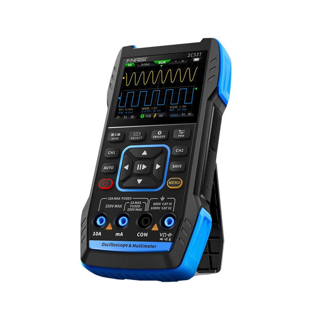
FNIRSI FNIRSI 2C53T (3-in-1) 2-ch Oscilloscope (50 MHz) + Multimeter + Signal Generator
The FNIRSI 2C53T, an enhanced version of its 10 MHz predecessor, is a compact and versatile 3-in-1 device. It combines a dual-channel 50 MHz oscilloscope, a 4.5-digit True RMS multimeter, and a signal generator with 13 waveform types, making it an essential tool for maintenance and research professionals. Oscilloscope: Features 50 MHz bandwidth, 250 MS/s sampling rate, ±400 V protection, FPGA + ARM + ADC architecture, and waveform saving for analysis. Multimeter: 4.5-digit True RMS with 19999 counts, supports AC/DC voltage, current, capacitance, resistance, diode, and continuity measurements. Signal Generator: Outputs 13 signal types up to 50 KHz, with adjustable frequency, amplitude, and duty cycle. With a 2.8-inch LCD, 3000 mAh battery (6-hour runtime), and a portable design, it delivers powerful functionality in a user-friendly package. Specifications Oscilloscope Channels 2 Analog Bandwidth 50 MHz Real-time Sampling Rate 250 MS/s Storage Depth 1 Kpts Impedance 1 MΩ Time Base Range 10ns-20s Vertical Sensitivity 10 mV/div-10 V/div (x1) Maximum Measured Voltage ±400 V Trigger Mode Auto/Normal/Single Trigger Type Rising edge, Falling edge Display Mode Y-T/Rolling/X-Y Coupling Method AC/DC Persistence OFF, 500ms, 1s, ∞ Math 8 Basic Operations + FFT Supported Waveform Screenshot Save, Export Waveform Image, Cursor Measurement, Infinite Afterglow Multimeter DC Voltage 1.9999V/19.999V/199.99V/1000V ±(0.5%+3) AC Voltage 1.9999V/19.999V/199.99V/750.0V ±(1%+3) DC Current 19.999mA/199.99mA/1.9999A/9.999A ±(1.2%+3) AC Current 19.999mA/199.99mA/1.9999A/9.999A ±(1.5%+3) Resistance 19.999MΩ/1.9999MΩ/199.99KΩ/19.999KΩ ±(0.5%+3) 1.9999KΩ/199.99Ω ±(2.0%+3) Capacitance 999.9uF/99.99uF/9.999uF/999.9nF/99.99nF/9.999nF ±(2.0%+5) 9.999mF/99.99mF ±(5.0%+20) Temperature −55~1300°C (−67~2372°F) ±(2.5%+5) Continuity Test Yes Diode Yes Signal Generator 13 Signal Waveforms Sine wave, rectangular wave, sawtooth wave, half wave, full wave, positive step wave, reverse step wave, exponential rise, exponential fall, DC, multi-audio, Sinker pulse, Lorentz wave Output Frequency 0-50 KHz Output Amplitude 0-3 V Output Duty Cycle 0-100% General Display 2.8" HD color screen Resolution 320 x 240 Charging USB-C (5 V/1 A) Battery 3000 mAh Lithium battery Standby Time 6 hours Languages English, Chinese Dimensions 167 x 89 x 35 mm Weight 300 g Differences New vs Old Version Model 2C53T Upgrade 2C53T Predecessor Bandwidth 50 MHz 10 MHz Display Mode Y-T/Rolling/X-Y Y-T/Rolling Math 8 Basic Operations + FFT N/A Cursor Function Yes N/A XY Lissau Graph Yes N/A Afterglow Function Yes N/A Multimeter Accuracy 19999 Counts 9999 Counts Signal Generator 50 KHz 2 MHz Included 1x FNIRSI 2C53T Oscilloscope (50 MHz) 2x P6100 Oscilloscope probes (10X) 1x Multimeter probe 1x Alligator clip probe 1x USB-C charging cable 1x Storage bag 1x Manual Downloads Manual Firmware V1.2.0
-

Elektor Labs Elektor Dual DC LISN (150 kHz – 200 MHz)
Measuring conducted emission is the simplest and most affordable method of getting some indication of whether a design can meet EMI/EMC requirements. A Line Impedance Stabilization Network (LISN) is an indispensable part of an EMC pre-compliance test setup. In cooperation with Würth Elektronik, Elektor has developed a 5 µH, 50 Ω Dual DC LISN that supports voltages up to 60 V and currents up to 10 A. The instrument measures RF interferences on both channels (the power supply) by means of 5-μH blocking inductances. The internal 10-dB attenuation network – one in each channel – contains a 3rd-order high-pass filter with a cutoff frequency of 9 kHz to protect the input of instruments like a spectrum analyzer from potentially harmful DC voltages or low frequencies coming from the EUT (Equipment Under Test). Specifications RF path Channels 2 (with clamping diodes) Bandwidth 150 kHz – 200 MHz Inductance 5 μH || 50 Ω Internal attenuation 10 dB Connectors SMA DC path Max. current < 10 ADC Max. voltage < 60 VDC DC resistance < 2 x 70 mΩ PCB size 94.2 x 57.4 mm Connectors 4-mm banana Hammond enclosure Type 1590N Dimensions 121 x 66 x 40 mm Included 1x 4-layer PCB with all SMT parts fitted 1x pre-drilled enclosure with ready-printed front panel layout 5x gold-plated, insulated, 4-mm banana sockets, rated for 24 A, 1 kV 1x Hammond enclosure 1590N1, Aluminum (Die-Cast Alloy) More Info Project on Elektor Labs: Dual DC LISN for EMC pre-compliance testing Elektor 9-10/2021: EMC Pre-Compliance Test for Your DC-Powered Project (Part 1) Elektor 11-12/2021: EMC Pre-Compliance Test for Your DC-Powered Project (Part 2)
-

Elektor Janvier/Février 2025 (FR)
Le téléchargement intégral de ce numéro est disponible pour nos membres GOLD et GREEN sur le site Elektor Magazine ! Pas encore membre ? Cliquez ici. stockage de l’énergieRéalisez votre propre stockage d’énergie pour réseau de panneaux photovoltaïques simulateur de panneau solaireUne solution pour tester et optimiser les trackers MPP et les onduleurs le concours STM32 Edge AIDécouvrez le STM32N6 et gagnez les 5000 € du concours ! Matériaux à large bande interditePourquoi y a-t-il un tel intérêt pour le SiC et le GaN ? batterie externe pour ordinateur portableProlongez la durée de vie de votre vieil ordinateur portable robots médicauxSurmonter les obstacles techniques et réglementaires prévention du gel pour les vergersavec enregistrement des températures The Analog ThingL'Arduino de l’ordinateur analogique ? commande de relais à faible consommation d'énergieÉconomiser 90% de la puissance de commande amélioration de la charge DC ET5410A+pour un meilleur refroidissement et moins de bruit electronica 2024 : rétrospective compatibilité électromagnétiqueLa CEM en quelques mots ! démarrer en électronique......Filtres actifs réduisez les pertes des chutes de tension avec des condensateursprofitez astucieusement de la réactance capacitive le MCP4725 : un convertisseur numérique-analogique 12 bits pas cheravec une fonction EEPROM pour un comportement sûr au démarrage la pince de test intelligente Fnirsi LCR-ST1 pour CMS labo de test et de mesure personnel basé sur Raspberry PiPour commencer : l'ADC une charge électroniqueUn projet prêt à l'emploi 2025 : l'odyssée de l'IAQuelques projets pour le nouvel an AmpVolt v2.0 : mise à jour100 A et plus ! projet 2.0Corrections, mises à jour et courrier des lecteurs transparence éthiqueCe que révèle l’enquête réalisée par Ethics in Electronics carte Elektor Audio DSP FX Processor (2)Création d'applications
€ 15,50
-

Elektor 09-10/2025 (DE)
Diese Ausgabe steht allen GOLD- und GREEN-Mitgliedern auf der ElektorMagazine-Website zum Download bereit! Sie sind noch kein Mitglied? Hier klicken! ESP32-Audio-Transceiver-Board (Teil 2)Drahtlose Audioübertragung Induktiver AM-SenderPIO des Pico in einem Arduino-Sketch Navigieren durch drahtlose ProtokolleEin technischer Leitfaden Satellitenverfolgung mit LoRaDas TinyGS-Netzwerk: Raumfahrtdaten gelangen zur Erde 4G-kompatible SMS-FernbedienungSteuern Sie Ihr Zuhause per Telefon aus der Ferne Hochgeschwindigkeits-TastkopfHochohmige Eingänge für Signale bis 200 MHz Aus dem Leben gegriffenKafka KrakenSDREin phasenkohärenter SDR-Empfänger Geschwindigkeitstests mit dem RP2350Lohnt sich der Umstieg von Raspberry Pi Pico 1 auf Version 2? Kontaktlose E-Feld-Messungen (2)Ein Laser-Vibrometer zur Erfassung der Membranschwingungen Quarze und OszillatorenQuarzgenauigkeit durch die Kondensatorwahl verbessern Aller Anfang ...... ist gar nicht schwer: Spezielle Audio-ICs Einstieg ins Programmieren von Selbstbauprojekten SPECTRAN® V6 MobileModular konfigurierbarer Echtzeit-Spektrum-Analyzer für zuverlässige Messungen in allen Frequenzbereichen Die Zukunft der KI wird in Silizium geschmiedetEin Interview mit Anastasiia Nosova Autonomer Sensorknoten v2.0 (Systemarchitektur)Solarbetriebene Sensorplattform mit integriertem GPS, LoRaWAN und weiteren Funktionen Präzise PositionsbestimmungBluetooth Channel Sounding ausprobiert Die Zukunft der Wireless-KommunikationDie ultradünnen Festkörperbatterien von BTRY Testgetriebene Programmierung in der Firmware-Entwicklung Handy-gesteuertes ModellautoWLAN + ESP32 + Smartphone = Fernsteuerung 2025: Eine KI-OdysseeKI-Denkmodelle: die Gedankenketten-Revolution Solarladeregler mit MPP-TrackingTeil 3: Software und Inbetriebnahme Web-Streaming-Kamera mit Raspberry Pi ZeroVerwendung des ZeroTier-VPN
€ 15,90
-
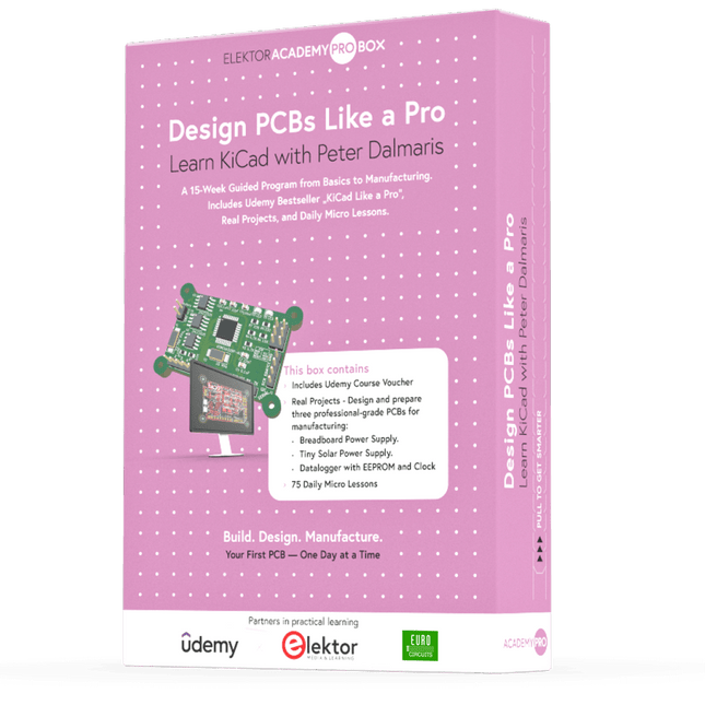
Elektor Academy Pro Design PCBs Like a Pro
Learn KiCad with Peter Dalmaris The Academy Pro Box "Design PCBs like a Pro" offers a complete, structured training programme in PCB design, combining online learning with practical application. Based on Peter Dalmaris’ KiCad course, the 15-week programme integrates video lessons, printed materials (2 books), and hands-on projects to ensure participants not only understand the theory but also develop the skills to apply it in practice. Unlike standard courses, the Academy Pro Box provides a guided learning path with weekly milestones and physical components to design, test, and produce working PCBs. This approach supports a deeper learning experience and better knowledge retention. The box is ideal for engineers, students, and professionals who want to develop practical PCB design expertise using open-source tools. With the added option to have their final project manufactured, participants complete the programme with real results – ready for use, testing, or further development. Learn by doing Build skills. Design real boards. Generate Gerbers. Place your first order. This isn’t just a course – it’s a complete project journey from idea to product. You’ll walk away with: Working knowledge of KiCad’s tools Confidence designing your own PCBs A fully manufacturable circuit board – made by you What's inside the Box (Course)? Both volumes of "KiCad Like a Pro" (valued at €105) Vol 1: Fundamentals and Projects Vol 2: Advanced Projects and Recipes Coupon code to join the bestselling KiCad 9 online course by Peter Dalmaris on Udemy, featuring 20+ hours of video training. You'll complete three full design projects: Breadboard Power Supply Tiny Solar Power Supply Datalogger with EEPROM and Clock Voucher from Eurocircuits for the production of PCBs (worth €85 excl. VAT) Learning Material (of this Box/Course) 15-Week Learning Program ▶ Click here to open Week 1: Setup, Fundamentals, and First Steps in PCB Design Week 2: Starting Your First PCB Project – Schematic Capture Week 3: PCB Layout – From Netlist to Board Design Week 4: Design Principles, Libraries, and Workflow Week 5: Your First Real-World PCB Project Week 6: Custom Libraries – Symbols, Footprints, and Workflow Week 7: Advanced Tools – Net Classes, Rules, Zones, Routing Week 8: Manufacturing Files, BOMs, and PCB Ordering Week 9: Advanced Finishing Techniques – Graphics, Refinement, and Production Quality Week 10: Tiny Solar Power Supply – From Schematic to Layout Week 11: Tiny Solar Power Supply – PCB Layout and Production Prep Week 12: ESP32 Clone Project – Schematic Design and Layout Prep Week 13: ESP32 Clone – PCB Layout and Manufacturing Prep Week 14: Final Improvements and Advanced Features Week 15: Productivity Tools, Simulation, and Automation KiCad Course with 18 Lessons on Udemy (by Peter Dalmaris) ▶ Click here to open Introduction Getting started with PCB design Getting started with KiCad Project: A hands-on tour of KiCad (Schematic Design) Project: A hands-on tour of KiCad (Layout) Design principles and PCB terms Design workflow and considerations Fundamental KiCad how-to: Symbols and Eeschema Fundamental KiCad how-to: Footprints and Pcbnew Project: Design a simple breadboard power supply PCB Project: Tiny Solar Power Supply Project: MCU datalogger with build-in 512K EEPROM and clock Recipes KiCad 9 new features and improvements Legacy (from previous versions of KiCad) KiCad 7 update (Legacy) (Legacy) Gettings started with KiCad Bonus lecture About the Author Dr. Peter Dalmaris, PhD is an educator, an electrical engineer and Maker. Creator of online video courses on DIY electronics and author of several technical books. As a Chief Tech Explorer since 2013 at Tech Explorations, the company he founded in Sydney, Australia, Peter's mission is to explore technology and help educate the world. What is Elektor Academy Pro? Elektor Academy Pro delivers specialized learning solutions designed for professionals, engineering teams, and technical experts in the electronics and embedded systems industry. It enables individuals and organizations to expand their practical knowledge, enhance their skills, and stay ahead of the curve through high-quality resources and hands-on training tools. From real-world projects and expert-led courses to in-depth technical insights, Elektor empowers engineers to tackle today’s electronics and embedded systems challenges. Our educational offerings include Academy Books, Pro Boxes, Webinars, Conferences, and industry-focused B2B magazines – all created with professional development in mind. Whether you're an engineer, R&D specialist, or technical decision-maker, Elektor Academy Pro bridges the gap between theory and practice, helping you master emerging technologies and drive innovation within your organization.


