
Search results for "esp OR 32s OR pinboard OR breakout OR modules"
-
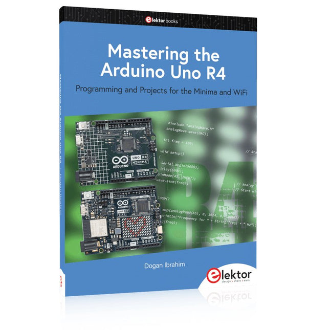
Elektor Publishing Mastering the Arduino Uno R4
Programming and Projects for the Minima and WiFi Based on the low-cost 8-bit ATmega328P processor, the Arduino Uno R3 board is likely to score as the most popular Arduino family member, and this workhorse has been with us for many years. Eleven years later, the long-overdue successor, the Arduino Uno R4, was released. It is built around a 48 MHz, 32-bit Arm Cortex-M4 microcontroller and provides significantly expanded SRAM and Flash memory. Additionally, a higher-precision ADC and a new DAC are added to the design. The Uno R4 board also supports the CAN Bus with an interface. Two versions of the board are available: Uno R4 Minima, and Uno R4 WiFi. This book is about using these new boards to develop many different and interesting projects with just a handful of parts and external modules. All projects described in the book have been fully tested on the Uno R4 Minima or the Uno R4 WiFi board, as appropriate. The project topics include the reading, control, and driving of many components and modules in the kit as well as on the relevant Uno R4 board, including LEDs 7-segment displays (using timer interrupts) LCDs Sensors RFID Reader 4x4 Keypad Real-time clock (RTC) Joystick 8×8 LED matrix Motors DAC (Digital-to-analog converter) LED matrix WiFi connectivity Serial UART CAN bus Infrared controller and receiver Simulators … all in creative and educational ways with the project operation and associated software explained in great detail.
€ 44,95
Members: € 40,46
-

Elektor Digital Elektor September/Oktober 2023 PDF (NL)
Elektor GREEN en GOLD leden kunnen deze uitgave hier downloaden.Nog geen lid? Klik hier om een lidmaatschap af te sluiten. Raspberry Pi Pico als spectrumanalyzerFFT’s met goedkope hardware ±40 V lineaire spanningsregelaaralternatieve voeding voor de Fortissimo-100 eindversterker... en andere! Flexibele draadloze communicatie met een MCUEEPROM opent netwerkmogelijkheden voor draadloze MCU’s € 5000 voor het oprapen!doe mee aan de STM32 Wireless Innovation Design Contest 2023: een AI-odysseeaan de slag met Code Interpreter van ChatGPT LoRa – een Zwitsers zakmesdeel 1: het LoRa-protocol en zijn voordelen Instelbare current sink met geïntegreerde klokgeneratortest voedingen, spanningsconverters en accu’s Twee nieuwe Arduino UNO R4-boards: Minima en WiFi Logaritmische potentiometersze zijn exponentieel! Motordriver breakout-boardeen BoB voor een 5 A DC-motordriver van 3×3 mm Uit het leven gegrepenelektronica periculosa Biedt cellulair het laagste stroomverbruik voor IoT?energie-eisen van LTE-M en NB-IoT in LPWAN-implementaties Draadloze communicatie in IoT-systemen met Arduino MKR-moduleshet juiste board voor WiFi, LoRa en andere standaarden AC-verliezen in magnetische componentenvoorkom hete spoelen! Meten voor optimale cloud-connectiviteit Matter implementatie: Wat is er nodig om Matter-devices in te zetten? YARD Stick Onesub-1 GHz draadloos testtool Houdrelaisvreemde onderdelen PIC voor tien – precies op tijdontwerp van een SDR-tijdseinontvanger Due Diligence DirectiveBusiness as Usual Will Not Do Alle begin......versterkt spanningen Infrageluid-recorder met de Arduino Pro Minieen voorbeeldproject uit de Elektor-uitgave “Arduino & Co” Cloud-gebaseerde energiemetermet een ESP32-module en een PZEM-004T spanning/stroom-sensor Een gids voor puristisch programmeren (deel 2)nauwkeurige timing, de UART en debugging
€ 9,95
-
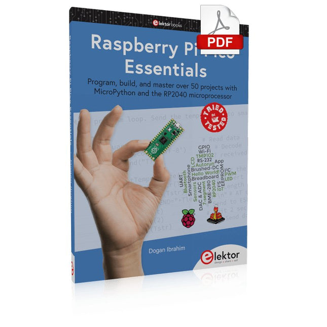
Elektor Digital Raspberry Pi Pico Essentials (E-book)
Program, build, and master over 50 projects with MicroPython and the RP2040 microprocessor The Raspberry Pi Pico is a high-performance microcontroller module designed especially for physical computing. Microcontrollers differ from single-board computers, like the Raspberry Pi 4, in not having an operating system. The Raspberry Pi Pico can be programmed to run a single task very efficiently within real-time control and monitoring applications requiring speed. The ‘Pico’ as we call it, is based on the fast, efficient, and low-cost dual-core ARM Cortex-M0+ RP2040 microcontroller chip running at up to 133 MHz and sporting 264 KB of SRAM, and 2 MB of Flash memory. Besides its large memory, the Pico has even more attractive features including a vast number of GPIO pins, and popular interface modules like ADC, SPI, I²C, UART, and PWM. To cap it all, the chip offers fast and accurate timing modules, a hardware debug interface, and an internal temperature sensor. The Raspberry Pi Pico is easily programmed using popular high-level languages such as MicroPython and or C/C++. This book is an introduction to using the Raspberry Pi Pico microcontroller in conjunction with the MicroPython programming language. The Thonny development environment (IDE) is used in all the projects described. There are over 50 working and tested projects in the book, covering the following topics: Installing the MicroPython on Raspberry Pi Pico using a Raspberry Pi or a PC Timer interrupts and external interrupts Analogue-to-digital converter (ADC) projects Using the internal temperature sensor and external temperature sensor chips Datalogging projects PWM, UART, I²C, and SPI projects Using Wi-Fi and apps to communicate with smartphones Using Bluetooth and apps to communicate with smartphones Digital-to-analogue converter (DAC) projects All projects given in the book have been fully tested and are working. Only basic programming and electronics experience is required to follow the projects. Brief descriptions, block diagrams, detailed circuit diagrams, and full MicroPython program listings are given for all projects described. Readers can find the program listings on the Elektor web page created to support the book.
€ 32,95
Members: € 29,66
-

Elektor Digital Elektor Septembre/Octobre 2023 (PDF)
Le téléchargement intégral de ce numéro est disponible pour nos membres GOLD et GREEN sur le site Elektor Magazine ! Pas encore membre ? Cliquez ici. Raspberry Pi Pico comme analyseur de spectredes FFT avec du matériel bon marché régulateur de tension linéaire ±40 Vune alimentation de qualité pour l'amplificateur de puissance Fortissimo-100... et d'autres ! la communication sans fil des microcontrôleurs devient flexiblel'EEPROM ouvre des perspectives de mise en réseau pour les microcontrôleurs sans fil 5000 ? à gagner !participez au concours STM32 Wireless Innovation Design Contest 2023 : l'odyssée de l'IAdémarrer avec l'interpréteur de code de ChatGPT LoRa, un couteau suisse (1)le protocole LoRa et ses avantages puit de courant réglable avec générateur d'horloge intégrétestez vos alimentations, convertisseurs de tension et batteries les nouvelles cartes Arduino UNO R4 Minima et WiFi des potentiomètres logarithmiquesqui sont exponentiels ! Carte d'interface pour pilote de moteurUn BoB pour un pilote de moteur à courant continu de 5 A avec une taille de 3×3 mm sur le vifdanger de l'électronique une architecture cellulaire offre-t-elle la plus basse consommation pour l'Internet des objets (IdO) ?caractéristiques énergétiques des technologies LTE-M et NB-IoT pour le déploiement de réseaux étendus à basse consommation (LPWAN) communication sans fil dans les systèmes IoT à l'aide de modules Arduino MKRnormes de communication des modules Arduino pour l'IoT pertes en courant alternatif dans les composants magnétiquesévitez la surchauffe des inductances ! optimiser son déploiement cloud grâce aux appareils de mesure implémentation de Matter : que faut-il pour déployer les appareils Matter ? le YARD Stick Oneun outil de test sans fil pour les fréquences jusqu?à 1 GHz relais à verrouillagedrôle de composant, la série PIC O?Clock ? prendre le pouls du tempsconception d'un récepteur de signaux horaires SDR Due Diligence DirectiveBusiness as Usual Will Not Do démarrer en électronique?amplificateur de tension enregistreur d'infrasons avec l'Arduino Pro Miniun projet extrait du livre 'Arduino & Co.' d'Elektor compteur d'énergie basé sur le cloudavec un module ESP32 et un capteur de tension/courant PZEM-004T guide de programmation Bare-Metal (2)timer précis, UART et débogage Hexadoku
€ 10,95
-

Elektor Labs Elektor Low-Noise Lab Power Supply
The Elektor Low-Noise Lab Power Supply is a fully analogue, adjustable, medium-power symmetrical bench supply that contains no switching or digital components. It provides an output voltage adjustable between 0 V and ±22 V, and an output current adjustable from 0 A to 1 A. Because it avoids any form of switching circuitry, the design delivers extremely low noise. To display both output voltages and currents, four miniature moving-coil panel meters are used. Most modern laboratory power supplies and AC adapters employ switch-mode techniques. Even the best examples inevitably exhibit high-frequency ripple and other switching artefacts on their output, which can interfere with the testing of sensitive analogue circuits and disturb low-level measurements. To overcome this, the concept here is a completely analogue power supply. Although less efficient than its switch-mode counterparts, the reduced efficiency is of little importance for test-bench use and ensures cleaner, more reliable measurement results. Because many analogue circuits require a symmetrical supply, this design delivers positive and negative output voltages of equal magnitude. A small amount of adjustment is available to compensate for any imbalance. Naturally, a variable current-limit function is also included. The kit includes the components required to build the power supply, except for the transformers. Specifications Output Voltage 0…+22 V, 0, −22 V Output Current 0…+1 A, 0…−1 A Noise −85 dBV, (at 0.95 A/20 V, B = 22 kHz) −84 dBV (at 0.95 A/20 V, B > 500 kHz) Ripple 50 µVRMS (at 950 mA/20 V, B = 22 kHz, mainly 100 Hz component) Included 3x PCBs: Regulator (PCB-1), Mains Filter (PCB-2) and Transformer (PCB-3) All the components except the AC transformers 4x moving-coil meters Additional parts for wiring (wires, banana sockets, IEC Power entry module, etc.) Not included The three AC transformers An enclosure Parts List For the Regulator PCB (240386-1) Resistors (250 mW, 1%) R1 = 12 Ω R2, R8, R37, R62 = 1 MΩ R3, R7, R10, R13, R17, R20, R22, R30, R35, R42, R45, R47, R55, R60 = 100 Ω, 600 mW R4, R5 = 4.7 kΩ R6 = 100 kΩ R9, R12, R14, R36, R38, R39, R61, R63, R66, R72, R78, R79 = 10.0 kΩ, 600 mW R11 = 9.76 kΩ, 600 mW R15, R40 = 44.2 kΩ, 600 mW R16, R41, R77 = 1 kΩ R18, R43 = 1.5 kΩ, 1 W, 5% R19, R44 = 470 Ω, 1 W, 5% R21, R46 = 330 Ω, 600 mW R23, R24, R48, R49 = 1.0 Ω, 1 W R25, R50 = 1 kΩ, 1 W, 5% R26, R28, R51, R53 = 1.000 kΩ 0.1%, 15 ppm/C R27, R29, R52, R54 = 10.00 kΩ 0.1%, 15 ppm/C R31, R56 = 1.2 kΩ, 1 W, 5% R32, R57 = 47 kΩ R33, R58 = 270 Ω R34, R59 = 27 kΩ R64, R69 = 12.0 kΩ R65 = 3.0 kΩ, 600 mW R67, R80 = 470 Ω, 600 mW R68, R70 = 6.8 kΩ, 600 mW R71 = 30.0 kΩ,, 600 mW R73, R74, R75, R76 = 10 MΩ P1, P2, P3 = 10 kΩ, 200 mW, 20%, potentiometer, 1 turns, single, lin., panel mount P4, P5 = 500 Ω, 500 mW, 10%, trimmer, 25 turns, 3296Y-1-501LF Bourns P6, P7 = 10 kΩ, 500 mW, 10%, trimmer, 25 turns, 3296Y-1-501LF Bourns Capacitors C1 = 100 nF, 50 V, 10%, ceramic X7R, LS 5 mm C2, C3, C6, C7, C30 = 10 µF, 63V, 20%, LS 2.5 mm, 3000hours@105°C C4, C5, C8, C9, C13, C14, C18, C19, C23, C24, C28, C29, C31, C32, C38, C39 = 100 nF, 250 V, 10%, PET, LS 7.5 mm C10, C20 = 47 nF, 100 V, 5%, PET, LS 5 mm C11, C21 = 10 nF, 100 V, 5%, PET, LS 5 mm C12, C22 = 220 µF, 35 V, 20%, 0.024 Ω, LS2.5/3.5 mm, Ir 3.4 A, 2000hours@125°C, polymer C15, C25 = 120 µF, 50 V, 20%, ESR 0.02 Ω, Diam. 10 mm max., LS 5 mm C16, C26 = 15 nF, 100 V, 5%, PET, LS 5 mm C17, C27 = 47 nF, 100 V, 5%, PET, LS 5 mm C33, C34 = 22 µF, 50 V, 20%, LS 2 mm, 10000 hours @ 105°C C35, C36, C44, C45 = 1 µF, 100 V, 10%, LS 5 mm, ceramic X7R C37 = 100 uF, 50 V, 20%. LS 3.5 mm C40, C41, C42, C43, C46, C47, C48, C49 = 1000 µF, 50 V, 20%, LS 5/7.5 mm, Ir 3.32 A, 10000hours@105°C, D 16 mm C50, C51, C52, C53 = 47 nF, 100 V, 10%, ceramic X7R, LS 5 mm Inductors L1, L2 = 4.7 µH, 3.2 A, 0.033 Ω, LS 5 mm, RLB0914-4R7ML Bourns L3 = Commom mode choke, 14.5 mH, 3 A, SSRH24NH-30145 Kemet Semiconductors D1, D2, D3, D4, D5, D9, D10, D11, D15 = BAT85, DO-34 D6, D7, D12, D13 = SR560, DO-201AD D8, D14, D16 = 1N4148, DO-35 D17 = Zenerdiode, 5.6 V, 0.5 W, DO-41 D18, D19 = 1N4004, DO-41 D20, D21 D22, D23 = V30100CI-M3/P, dual common cathode, TO-220 D24 = Zener diode, 30 V, 1 W, DO-41 LED1, LED2 = LED, red, T-1 (3 mm) LED3, LED4 = LED, green, T-1 (3 mm) TVS1, TVS2 = BZW50-33B, R6 T1, T2, T4 = BC337.25, TO-92 T3 = NJW0302G, TO-3P T5, T6, T8 = BC327.25, TO-92 T7 = NJW0281G, TO-3P T9 = BD139, TO-126 (SOT-32) IC1 = LM334Z, TO-92 IC2 = LM4040AIZ-5.0/NOPB, TO-92 (TO-226AA-3) IC3, IC4 = OPA2992IDR, SOIC-8 IC5, IC6 = OPA4992IDR, SOIC-14 IC7 = OPA992IDBVR, SOT-23-5 IC8 = LM339N, DIP-14 IC9 = LM317, TO-220 IC10 = LM337, TO-220 Others F1, F2 = 5×20 mm fuse, 1.6 A, fast acting HS1, HS2 = Heatsink MC33271 (for T3/T7), 2.7°C/W, PCB mount, height 63.5 mm K1, K4 = 3-way screw terminal block, LS 3.5 mm, max. 1.5 mm² K2, K3 = 3-way screw terminal block, LS 3.5 mm, max. 1 mm² M1, M3 = Moving coil meter, Range 30 V, type 91C4, 45×45 mm M2, M4 = Moving coil meter, Range 1 A, type 91C4, 45×45 mm² RE1 = Relay DPDT,5V, UA2-5NU Miscellaneous 3× 3-way screw terminal block, LS 3.5 mm, max. 1 mm² (for P1, P2, P3) 4× Pin header, 1×2, vertical, pitch 2.54 mm (for LED1, LED2, LED3, LED4) 4× Pin socket, 1×2, vertical. pitch 2.54 mm (for LED1, LED2, LED3, LED4) 2× Heatsink FK222SA220, 20°C/W, PCB mount (for IC9 & IC10) 2× Mica thermal pad for TO-220, 12×18×0.05 mm (for IC9 & IC10) 2× Insulating bushing IB 6, TO-220 (for IC9 & IC10) 2× Ceramic thermal pad, 23×20×2 mm (for T3 & T7) 2× PCB Fuse Holder, for 5×20 mm fuse, 10 A (for F1, F2) 2× Cover for PCB Fuse Holder, transparent (for F1, F2) 2× 2-way screw terminal block, LS 3.5 mm, max. 1 mm² (for M1 & M3) 2× 2-way screw terminal block, LS 3.5 mm, max. 1.5 mm² (for M2 & M4) 8× M3 solder lug, thickness 0.35 mm (for M1…M4) M4 solder lug, thickness 0.35 mm (to connect 4 mm banana connectors) Screened cable, 1 pair, 2×24 AWG/0.22 mm², 1 m (for P1, P2 & P3) IC socket, DIP, 14 contacts (for IC8) M3 washer, plain, steel M3 screw, 16 mm, steel, pan head M3 nut M3 spring washer 50 mm M3 standoff, steel, male-female 12 mm M3 standoff, steel, male-female 10 mm M3 standoff, steel, male-female M3 screw, 8 mm, steel, pan head For the Mains Fiter PCB (240386-2) Resistor R1 = 220 kΩ, 1 W, 500 V, 5% Capacitors C1, C2 = 470 nF, 305 VAC, Class X2, 11 × 27 mm max., LS 15/22.5 mm C3, C4, C5, C6 = 2.2 nF, 300 VAC, Class Y2, 13 × 4 mm, LS 10 mm, PP Inductors L1, L2 = Common-mode choke, 6.8 mH, 1.7 A, TDK B82732R2172B030 Semiconductor MOV1 = TVS varistor, 300 VAC, S14K300 (230 VAC, B72214S0301K101) and SK14K150 (150 VAC, B72214S0151K101) Others K1, K2 = 3-way screw terminal block, LS 7.62 mm F1 = Time-delay fuse, 0.5 A (230 VAC) or 1 A (115 VAC) Miscellaneous 1× Fuse holder, 5×20 mm, 10 A, 500 VAC 1× Transparent fuse cover 4× 10 mm M3 standoff, steel, male–female 4× M3 screw, 8 mm, steel, pan head 4× M3 nut For the Transformer PCB (240386-3) Resistors R1, R2 = 2.7 kΩ, 600 mW, 1% R3 = 10.0 kΩ, 600 mW, 1% Capacitor C1 = 220 µF, 50 V, 20%, Ø10 mm, LS 5 mm, 4000 h @ 105°C Transformers (not included in this kit!) TR1, TR2, TR3 = 2×7 V, 25 VA, PCB-mounted toroid, 70060K Talema Semiconductors D1–D4 = 1N4148, DO-35 D5, D6 = 1N4004, DO-41 D7 = Zener 5.6 V, 1.3 W, DO-41 LED1 = LED, red, T-1 (3 mm) IC1, IC2 = MOC8021M, CTR ≥ 1000%, DIP-6 Others F1, F2, F3 = 160 mA time-delay fuse (230 VAC) or 315 mA time-delay fuse (115 VAC) K1 = 2-way screw terminal block, LS 7.62 mm K2 = 3-way screw terminal block, LS 3.5 mm, max 1.5 mm² K3, K4 = 3-way screw terminal block, LS 3.5 mm, max 1 mm² RE1, RE2 = Relay DPDT, 5 A/250 VAC / 24 VDC Miscellaneaous 1× Pin header 1×2, pitch 2.54 mm + matching socket for LED1 3× Fuse holder 5 × 20 mm, 10 A, 500 VAC + transparent cover 3× M4 screw, 8 mm, pan head + washer for TR1-TR3 8× M3 screw, 8 mm, pan head + nut + washer 8× 10 mm M3 standoff, steel, male–female 2× IC socket, DIP-6 for IC1 & IC2 Additional Parts 1 m red insulated wire, stranded, 1.5 mm² 0.5 m blue insulated wire, stranded, 1.5 mm² 0.5 m black insulated wire, stranded, 1.5 mm², 0.5 m 2 m red insulated wire, stranded, D 0.56 mm (0.25 mm²) 2 m black insulated wire, stranded, D 0.56 mm (0.25 mm²) 0.5 m Multicore Cable, Flexible, 3 Core, 0.75 mm² (24 x 0.2 mm) Red banana socket Black banana socket Blue banana socket Green banana socket IEC Power Entry Module with switch, IEC C14 3 crimp terminals, FASTON, 4.75 x 0.81 mm 3 knobs Links Elektor Labs JumpStarter Page Article (Part 1) Article (Part 2)
€ 299,00€ 249,00Best Price
-

Elektor Digital Inside an Open-Source Processor (E-book)
An Introduction to RISC-V RISC-V is an Instruction Set Architecture (ISA) that is both free and open. This means that the RISC-V ISA itself does not require a licensing fee, although individual implementations may do so. The RISC-V ISA is curated by a non-profit foundation with no commercial interest in products or services that use it, and it is possible for anyone to submit contributions to the RISC-V specifications. The RISC-V ISA is suitable for applications ranging from embedded microcontrollers to supercomputers. This book will first describe the 32-bit RISC-V ISA, including both the base instruction set as well as the majority of the currently-defined extensions. The book will then describe, in detail, an open-source implementation of the ISA that is intended for embedded control applications. This implementation includes the base instruction set as well as a number of standard extensions. After the description of the CPU design is complete the design is expanded to include memory and some simple I/O. The resulting microcontroller will then be implemented in an affordable FPGA development board (available from Elektor) along with a simple software application so that the reader can investigate the finished design.
€ 32,95
Members: € 29,66
-

Elektor Digital Elektor 01-02/2023 (PDF)
Diese Ausgabe steht allen GOLD- und GREEN-Mitgliedern auf der ElektorMagazine-Website zum Download bereit! Sie sind noch kein Mitglied? Hier klicken! Für Augen und Ohren Videoausgabe mit MikrocontrollernTeil 1: Composite Video electronica 2022Neues von der Weltleitmesse ESP32-KameraSo einfach, dass sie nicht einmal WLAN braucht ATX-Netzteil für Raspberry Pi 32-?-KopfhörerverstärkerEinfache, aber hochqualitative 3-Chip-Lösung SDR-FunkuhrenFünf Zeitzeichen, sechs Anzeigen Aller Anfang ...muss nicht schwer sein: Spezielle Dioden Aus dem Leben gegriffenÜber die Qualität der Dinge Reverse-Engineering eines LED-Displays mit Bluetooth Low EnergyWie man ein BLE-Gerät mit einem Python-Skript steuert MakePython ESP32 Development KitAlles in einer Box THD-Messung mit Oszilloskop und FFTDen Klirrfaktor einfach berechnen Allsehende MaschinenDie Technologie hinter modernen industriellen Bildverarbeitungssystemen Infografik Die Entwicklung der Sprach- und Audiosteuerung für elektronische Geräte WEEF 2022 im Rückblick Im Rückblick: FFWD electronica 2022Innovatoren beeindrucken weiterhin! The TubeEin Röhrenverstärker der anderen Art Biomaterialien in der Elektronik: Bereit oder nicht? Opera-Cake-Antennenumschalter für HackRF OneSchließen Sie bis zu acht Antennen an Ihr SDR an Technik mit Arduino und mehrEin Interview mit Autor Ashwin Pajankar LiDAR-PräzisionsmetermaßMisst bis zu zwölf Meter Audio mit dem ESP32Das Framework ESP-ADF in der Praxis Elektor-Leistungsverstärker-Bausatz Fortissimo-100 Licht für Klangeffekte nutzenLDR-basiertes spannungsgesteuertes 24 dB/Okt.-Synthesizer-Filter Hochleistungsverstärker GigantDer Lauteste von allen!! Betreten für Unbefugte verboten!Ein volumetrisches Display Made in Canada Projekt 2.0Korrekturen, Updates und Leserbriefe Hexadoku
€ 11,90
-

Elektor Digital Elektor 09-10/2026 (PDF) DE
Diese Ausgabe steht allen GOLD- und GREEN-Mitgliedern auf der ElektorMagazine-Website zum Download bereit! Sie sind noch kein Mitglied? Hier klicken! Der ESP-BLASTEine Mini-Raketendrohne mit ESP32, die über 100 km/h erreicht Wireless Workshop (1)Freigeschaltetes Funkmodul: 433-MHz-CC1101-Sub-GHz-Transceiver AM-Sendermit Rechteck-/Sinuswellengenerator auf Raspberry Pi Pico STM32Cube Innovations ChallengeTreten Sie mit Ihrem besten STM32C5-Design an CoffeeCallerWie ein langer Flur zu einer maßgefertigten Mesh-Netzwerk-Platine führte AudiotronicsKlirrfaktor Elektor ist 65Projekte aus früheren September/Oktober-Ausgaben Geräteortung durch Bluetooth Channel SoundingZentimetergenaue Entfernungsmessung im IoT der nächsten Generation 2026: Eine KI-OdysseeQuantencomputing ist nicht die nächste GPU Cloud-Schutz durch Edge-Sicherheit Erste Erfahrungen mit dem HackRF ProPraktische Tests mit der neuen SDR-Hardware Herausforderung ElektromobilitätEffiziente Lötlösungen für moderne Fahrzeugtechnik Modem-Update von GPRS/2G auf LTE/4Gam Beispiel einer Funk-Alarmzentrale Loop-Antenne mit RF BricksTeil 1: Kurzwellen-Antenne mit einstellbarer Richtwirkung im Selbstbau Internetradio-zu-AM-KonverterVerwendung eines ESP32-S3 als Sender Projekt 2.0 mioty – ein ÜberblickLPWAN à la Fraunhofer Werkbank-WeisheitPraktische Tipps von Experten Walter, das kompakte IoT-ModulTeil 2: Zugriff auf Wetter- und Datendienste
€ 11,90
-

Elektor Digital Elektor Januari/Februari 2023 PDF (NL)
Elektor GREEN en GOLD leden kunnen deze uitgave hier downloaden.Nog geen lid? Klik hier om een lidmaatschap af te sluiten. Voor ogen en oren Video-output met microcontrollers (1)Composiet Video electronica 2022nieuws van 's werelds grootste elektronicabeurs ESP32-camerazo simpel – heeft niet eens WiFi ATX-voeding voor Raspberry Pi 32 Ω KoptelefoonversterkerEenvoudige maar hoogwaardige 3-chip oplossing SDR-radioklokkenvijf tijdsignalen, zes displays Alle begin......zet een streep onder de diode Uit het leven gegrepenover de kwaliteit der dingen Reverse-engineering van een Bluetooth Low Energy LED-badgeeen BLE-apparaat besturen met een Python-script MakePython ESP32 Development KitAlles in een doosje THD-meting met een oscilloscoop en FFTgemakkelijke berekening van de vervormingsfactor Allesziende machinesde technologie achter moderne industrële visionsystemen Infographics De evolutie van spraak- en audiogestuurde elektronische apparaten WEEF 2022 terugblik FFWD elektronica 2022 terugblikde vernieuwers hebben niet nagelaten indruk te maken The Tubeeen ongebruikelijke buizenversterker Biomateriaal in elektronica: klaar of niet De Opera Cake antenne switch voor HackRF OneSluit tot acht antennes aan op uw SDR Engineering met de Arduino, en meerEen interview met auteur Ashwin Pajankar LiDAR-precisiemetermeet tot 12 meter Audiosignalen en de ESP32De ESP-ADF-omgeving in de praktijk Elektor Fortissimo-100 einversterker-kit Lichtgestuurde geluidseffectenSpanningsgestuurd 24 dB/oct synthesizerfilter (VCF) met LDR's De kilo-watter van Elektuurmeer volume gaat niet! Oost West Lab Besteen volumetrisch display in Canada Project 2.0Correcties, Updates en Brieven van lezers Hexadoku
€ 9,95
-
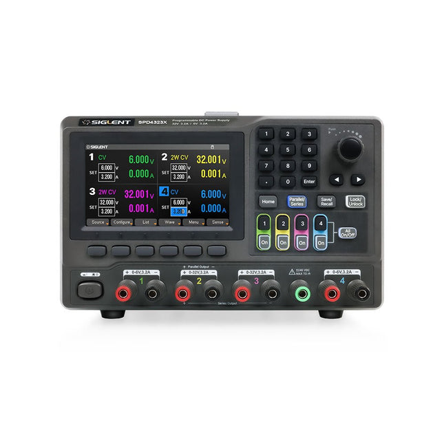
Siglent Siglent SPD4323X 4-ch DC Power Supply (240 W)
The Siglent SPD4323X is a 4-channel DC Linear Programmable Power Supply equipped with a 4.3-inch TFT-LCD display, friendly human-machine interface, and excellent performance indicators. Real-time waveform display provides engineers with an informative user interface. SPD4323X offers a total output power of 240 W with a resolution of 1 mV/1 mA. The maximum voltage and current for each channel are as follows: CH1: 6 V/3.2 A CH2: 32 V/3.2 A CH3: 32 V/3.2 A CH4: 6 V/3.2 A Features Rated output power: 240 W Rated voltage: 32 V, 12 V, 30 V Up to four high-precision power supplies with independent controllable outputs, supporting CH2 and CH3 series and parallel connections Clear graphical interface with waveform and timer display modes 5-digit voltage and current display with minimum resolution of 1 mV, 1 mA Fast output response time: <50us The high current channel support remote voltage compensation sense function. The maximum compensation voltage is 0.6 V Overvoltage protection and overcurrent protection or safe and accurate operation Equipped with a 4.3-inch TFT-LCD display (480 x 272 resolution) USB and LAN standard communication USB-GPIB module is optional Excellent channel density with up to 4 channels in a 3U half rack package Internal data storage for setups and parameters Embedded Web Server with instrument communication that doesn’t require software installation Fully SCPI programming command set support as well as a LabView driver for remote control and system automation Specifications SPD4323X SPD4121X SPD4306X Channel Output CH1: Voltage 0 to 6 V Current 0 to 3.2 ACH2: Voltage 0 to 32 V Current 0 to 3.2 ACH3: Voltage 0 to 32 V Current 0 to 3.2 ACH4: Voltage 0 to 6 V Current 0 to 3.2 A CH1: Voltage 0 to 15 V Current 0 to 1.5 ACH2: Voltage 0 to 12 V Current 0 to 10 ACH3: Voltage 0 to 12 V Current 0 to 10 ACH4: Voltage 0 to 15 V Current 0 to 1.5 A CH1: Voltage 0 to 15 V Current 0 to 1.5 ACH2: Voltage 0 to 30 V Current 0 to 6 ACH3: Voltage 0 to 30 V Current 0 to 6 ACH4: Voltage 0 to 15 V Current 0 to 1 A Resolution 1 mV, 1 mA 1 mV, 1 mA 1 mV, 1 mA Setting Accuracy Voltage: ±(0.03% of reading+10) mV, Current: ±(0.3% of reading+10) mA Voltage: ±(0.03% of reading+10) mV, Current: ±(0.3% of reading+10) mA Voltage: ±(0.03% of reading+10) mV, Current: ±(0.3% of reading+10) mA Readback Accuracy Voltage: ±(0.03% of reading+10) mV, Current: ±(0.3% of reading+10) mA Voltage: ±(0.03% of reading+10) mV, Current: ±(0.3% of reading+10) mA Voltage: ±(0.03% of reading+10) mV, Current: ±(0.3% of reading+10) mA Display 4.3" TFT-LCD 5-digit voltage and current display 4.3" TFT-LCD 5-digit voltage and current display 4.3" TFT-LCD 5-digit voltage and current display Output power 240 W 285 W 400 W Included 1x Siglent SPD4323X Power Supply 1x Power cord (EU) 1x Output test cord (3 A) 1x USB cable 1x Quick start guide Downloads Datasheet Manual Quick start
€ 762,30
-

Elektor Publishing Initiation au langage CircuitPython et à la puce nRF52840
En moins de 100 lignes de code par projet avec les cartes Feather Sense et Clue Express d'Adafruit Le langage de programmation Python est apprécié par les pédagogues parce que sa syntaxe le rend facile à comprendre. Il s'est également imposé chez les informaticiens expérimentés. La société Adafruit a développé une version spéciale de Python pour l'embarquer sur les microcontrôleurs à 32 bits : CircuitPython. Ce livre permettra au lecteur de s'initier à la programmation en CircuitPython sur deux cartes : Feather BlueFruit Sense (également appelée Feather nRF52840 Sense) et CLUE nRF52840 Express. Chacune est animée par le SoC nRF52840 de NORDIC avec une architecture à 32 bits. Pour ce voyage dans le monde de la programmation embarquée, l'auteur sort du chemin classique, à savoir un cours complet sur la programmation orientée objet appliquée à ce langage. Il préfère emmener le lecteur directement sur le terrain avec des projets qui mettent en oeuvre les cartes et différents périphériques. Plus d'une quarantaine d'exemples et de montages permettent de découvrir la richesse de CircuitPython. Toutefois l'auteur s'est imposé une limite pour ne pas décourager les novices : le code de chaque projet ne dépasse jamais la centaine de lignes. Pour ce qui est du matériel, là aussi la simplicité domine : aucun programmateur, un simple PC suffit ; aucun soudage grâce au câblage sur platine d'essai. Les cartes d'extension FeatherWing à enficher sur la Feather nRF52840 Sense permettent de démultiplier ses fonctions : matrice de LED, enregistreur de données, écran à encre électronique, écran OLED, écran TFT, commande de moteurs, audio, relais… Toutes les étapes (assemblage des différents composants, installation des bibliothèques requises, programmation, tests…) sont expliquées en détail. Le code des différents exemples et projets est disponible sur Github. Le résultat de chaque projet est même présenté sur de courtes vidéos disponibles sur YouTube. À la fin de sa lecture, le nouveau Pythonien pourra facilement approfondir les notions abordées et donner vie à ses propres projets grâce aux outils qu'il aura essayés. Ce livre s'adresse aux lycéens et étudiants ainsi qu'à toute la communauté des makers. Chaîne YouTube de l'auteur : YouTube (Michaël Bottin)
€ 44,95
Members: € 40,46
-
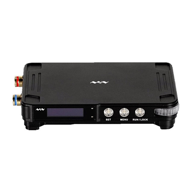
Miniware Miniware MDP-P906 Digital Power Supply (300 W)
MDP-P906 has a built-in cooling fan, and maximum output power of up to 300 W, which meets a wider range of testing needs and application scenarios. Through 2.4 GHz wireless communication, it can be connected to MDP-M01 Smart Digital Monitor module to realize the free combination of multiple channels of 300 W per channel. MDP-P906 has the index, stability and reliability comparable to a professional power supply. It can output pure current, and provide powerful functions such as programmable output, timing output, timing control, automatic compensation, boost mode, etc., making itself a real cost-effective, smart and customized programmable linear DC power supply. MDP-P906 adopts a precision CNC machined aluminum alloy shell, with fine workmanship, novel, mini and beautiful appearance, it completely subverts the rigid image of traditional desktop power supply. With stackable modular design and wireless communication function, MDP-P906 can work independently or paired, both on the workbench, and be carried out for on-site maintenance. MDP-P906 is a perfect solution for electronic engineer, especially field application engineers to meet different needs of power sources. Built-in silent cooling fan, instant cooling, ensure a stable and efficient output! Smart linear compensation, constant voltage & constant current Positive & negative output, series boost, parallel current sharing Applications Universal tests and teaching experiments in R&D laboratory Maintenance of digital products Property verification and fault diagnosis of devices and circuits Emergency power supply for model airplanes and vehicles Power supply testing of RF and microwave circuits or modules Quality control and quality inspection Supply purified power for high-accuracy digital-analog hybrid circuits and Hi-Fi audio devices Specifications Input DC 4.2-30 V/14 A (Max)QC 3.0/PD2.0, 20 V/5 A (Max) Output 0-30 V/0-10 A, 300 W (Max) Conversion efficiency 95% Output resolution 10 mV/2 mA, up to 1 mV/1 mA via Display Control module Output accuracy 0.03%+5 mV0.05%+2 mV Adjustment rate Load adjustment rate <±0.01%Power adjustment rate <±0.01% Ripple and noise <250 uVrms, 3 mVpp; 2 mArms Transient response <4 uS Safety protections Input over-voltage, under-voltage, reverse connection protection, output over-current, back-flow protection and over-temperature protection Others Automatically shut-down and enter micro-power modeSupport USB firmware upgrade Dimensions 112 x 66 x 20 mm Weight 181 g Included 1x MDP-P906 Digital Power Supply 2x Output Cable 1x User Manual Downloads User Manual v1.1 Firmware v1.32
€ 171,95


