
Products
-
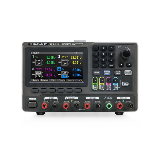
Siglent Siglent SPD4306X 4-ch DC Power Supply (400 W)
The Siglent SPD4306X is a 4-channel DC Linear Programmable Power Supply equipped with a 4.3-inch TFT-LCD display, friendly human-machine interface, and excellent performance indicators. Real-time waveform display provides engineers with an informative user interface. SPD4306X offers a total output power of 400 W with a resolution of 1 mV/1 mA. The maximum voltage and current for each channel are as follows: CH1: 15 V/1.5 A CH2: 30 V/6 A CH3: 30 V/6 A CH4: 15 V/1 A Features Rated output power: 400 W Rated voltage: 32 V, 12 V, 30 V Up to four high-precision power supplies with independent controllable outputs, supporting CH2 and CH3 series and parallel connections Clear graphical interface with waveform and timer display modes 5-digit voltage and current display with minimum resolution of 1 mV, 1 mA Fast output response time: <50us The high current channel support remote voltage compensation sense function. The maximum compensation voltage is 0.6 V Overvoltage protection and overcurrent protection or safe and accurate operation Equipped with a 4.3-inch TFT-LCD display (480 x 272 resolution) USB and LAN standard communication USB-GPIB module is optional Excellent channel density with up to 4 channels in a 3U half rack package Internal data storage for setups and parameters Embedded Web Server with instrument communication that doesn’t require software installation Fully SCPI programming command set support as well as a LabView driver for remote control and system automation Specifications SPD4323X SPD4121X SPD4306X Channel Output CH1: Voltage 0 to 6 V Current 0 to 3.2 ACH2: Voltage 0 to 32 V Current 0 to 3.2 ACH3: Voltage 0 to 32 V Current 0 to 3.2 ACH4: Voltage 0 to 6 V Current 0 to 3.2 A CH1: Voltage 0 to 15 V Current 0 to 1.5 ACH2: Voltage 0 to 12 V Current 0 to 10 ACH3: Voltage 0 to 12 V Current 0 to 10 ACH4: Voltage 0 to 15 V Current 0 to 1.5 A CH1: Voltage 0 to 15 V Current 0 to 1.5 ACH2: Voltage 0 to 30 V Current 0 to 6 ACH3: Voltage 0 to 30 V Current 0 to 6 ACH4: Voltage 0 to 15 V Current 0 to 1 A Resolution 1 mV, 1 mA 1 mV, 1 mA 1 mV, 1 mA Setting Accuracy Voltage: ±(0.03% of reading+10) mV, Current: ±(0.3% of reading+10) mA Voltage: ±(0.03% of reading+10) mV, Current: ±(0.3% of reading+10) mA Voltage: ±(0.03% of reading+10) mV, Current: ±(0.3% of reading+10) mA Readback Accuracy Voltage: ±(0.03% of reading+10) mV, Current: ±(0.3% of reading+10) mA Voltage: ±(0.03% of reading+10) mV, Current: ±(0.3% of reading+10) mA Voltage: ±(0.03% of reading+10) mV, Current: ±(0.3% of reading+10) mA Display 4.3" TFT-LCD 5-digit voltage and current display 4.3" TFT-LCD 5-digit voltage and current display 4.3" TFT-LCD 5-digit voltage and current display Output power 240 W 285 W 400 W Included 1x Siglent SPD4306X Power Supply 1x Power cord (EU) 1x Output test cord (3 A) 1x USB cable 1x Quick start guide Downloads Datasheet Manual Quick start
€ 1.101,10
-
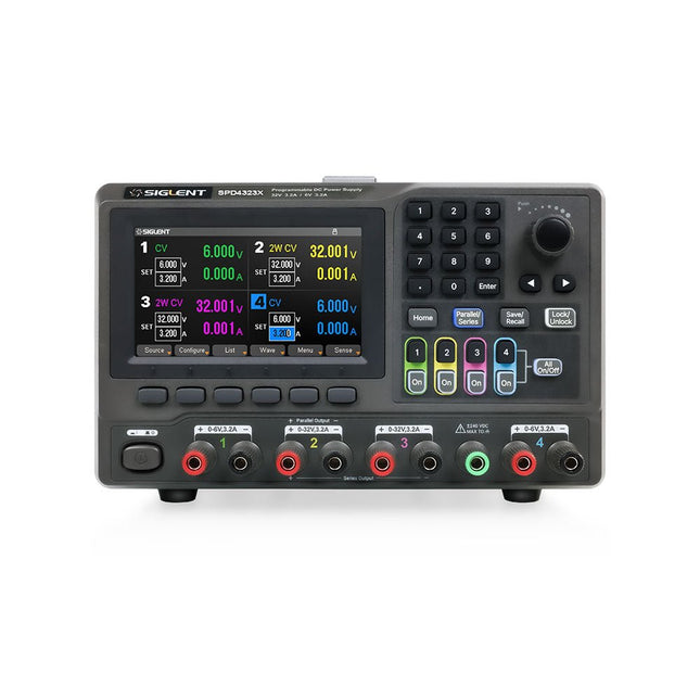
Siglent Siglent SPD4323X 4-ch DC Power Supply (240 W)
The Siglent SPD4323X is a 4-channel DC Linear Programmable Power Supply equipped with a 4.3-inch TFT-LCD display, friendly human-machine interface, and excellent performance indicators. Real-time waveform display provides engineers with an informative user interface. SPD4323X offers a total output power of 240 W with a resolution of 1 mV/1 mA. The maximum voltage and current for each channel are as follows: CH1: 6 V/3.2 A CH2: 32 V/3.2 A CH3: 32 V/3.2 A CH4: 6 V/3.2 A Features Rated output power: 240 W Rated voltage: 32 V, 12 V, 30 V Up to four high-precision power supplies with independent controllable outputs, supporting CH2 and CH3 series and parallel connections Clear graphical interface with waveform and timer display modes 5-digit voltage and current display with minimum resolution of 1 mV, 1 mA Fast output response time: <50us The high current channel support remote voltage compensation sense function. The maximum compensation voltage is 0.6 V Overvoltage protection and overcurrent protection or safe and accurate operation Equipped with a 4.3-inch TFT-LCD display (480 x 272 resolution) USB and LAN standard communication USB-GPIB module is optional Excellent channel density with up to 4 channels in a 3U half rack package Internal data storage for setups and parameters Embedded Web Server with instrument communication that doesn’t require software installation Fully SCPI programming command set support as well as a LabView driver for remote control and system automation Specifications SPD4323X SPD4121X SPD4306X Channel Output CH1: Voltage 0 to 6 V Current 0 to 3.2 ACH2: Voltage 0 to 32 V Current 0 to 3.2 ACH3: Voltage 0 to 32 V Current 0 to 3.2 ACH4: Voltage 0 to 6 V Current 0 to 3.2 A CH1: Voltage 0 to 15 V Current 0 to 1.5 ACH2: Voltage 0 to 12 V Current 0 to 10 ACH3: Voltage 0 to 12 V Current 0 to 10 ACH4: Voltage 0 to 15 V Current 0 to 1.5 A CH1: Voltage 0 to 15 V Current 0 to 1.5 ACH2: Voltage 0 to 30 V Current 0 to 6 ACH3: Voltage 0 to 30 V Current 0 to 6 ACH4: Voltage 0 to 15 V Current 0 to 1 A Resolution 1 mV, 1 mA 1 mV, 1 mA 1 mV, 1 mA Setting Accuracy Voltage: ±(0.03% of reading+10) mV, Current: ±(0.3% of reading+10) mA Voltage: ±(0.03% of reading+10) mV, Current: ±(0.3% of reading+10) mA Voltage: ±(0.03% of reading+10) mV, Current: ±(0.3% of reading+10) mA Readback Accuracy Voltage: ±(0.03% of reading+10) mV, Current: ±(0.3% of reading+10) mA Voltage: ±(0.03% of reading+10) mV, Current: ±(0.3% of reading+10) mA Voltage: ±(0.03% of reading+10) mV, Current: ±(0.3% of reading+10) mA Display 4.3" TFT-LCD 5-digit voltage and current display 4.3" TFT-LCD 5-digit voltage and current display 4.3" TFT-LCD 5-digit voltage and current display Output power 240 W 285 W 400 W Included 1x Siglent SPD4323X Power Supply 1x Power cord (EU) 1x Output test cord (3 A) 1x USB cable 1x Quick start guide Downloads Datasheet Manual Quick start
€ 762,30
-

Siglent Siglent SSA3015X Plus Spectrum Analyzer (9 kHz – 1.5 GHz)
The Siglent SSA3015X Plus spectrum analyzer is a powerful and flexible tool for RF signal and network analysis. With a frequency range of 1.5 GHz, the analyzer delivers reliable automatic measurements and multiple modes of operation: spectrum analyzer the base, optional functions include RF power measurement, vector signal modulation analysis, reflection measurement, and EMI test. Applications include broadcast monitoring/evaluation, site surveying, S-parameter measurement, analog/digital modulation analysis, EMI pre-compliance test, research and development, education, production, and maintenance. Features Spectrum Analyzer Frequency Range from 9 kHz to 1.5 GHz –156 dBm/Hz Displayed Average Noise Level (Typ.) –99 dBc/Hz. @ 10 kHz Offset Phase Noise (1 GHz, Typ.) Level Measurement Uncertainty <1.2 dB (Typ.) 1 Hz Minimum Resolution Bandwidth (RBW) Preamplifier (Std.) Tracking Generator (incl. free of charge) Analog and Digital Signal Modulation Analysis Mode (opt.) Reflection Measurement Kit (opt.) EMI Filter and Quasi-Peak Detector Kit (opt.) Advanced Measurement Kit (opt.) 10.1-inch Multi-Touch Screen , Mouse and Keyboard supported Web Browser Remote Control on PC and Mobile Terminals and File Operation Specifications SSA3015X Plus SSA3021X Plus SSA3032X Plus SSA3075X Plus Frequency Range 9 kHz ~ 1.5 GHz 9 kHz ~ 2.1 GHz 9 kHz ~ 3.2 GHz 9 kHz ~ 7.5 GHz Resolution Bandwidth 1 Hz ~ 1 MHz 1 Hz ~ 1 MHz 1 Hz ~ 1 MHz 1 Hz ~ 3 MHz Phase Noise <–99 dBc/Hz <–98 dBc/Hz <–98 dBc/Hz <–98 dBc/Hz Total Amplitude Accuracy <1.2 dB <0.7 dB <0.7 dB <0.7 dB Display Average Noise Level –156 dBm/Hz –161 dBm/Hz –161 dBm/Hz –165 dBm/Hz Included Siglent SSA3015X Plus spectrum analyzer USB cable Power cord Quick start guide Downloads Datasheet Manual Documentation Firmware
€ 1.402,39
-
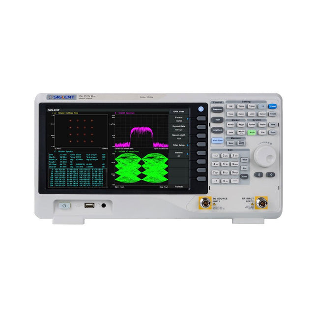
Siglent Siglent SSA3021X Plus Spectrum Analyzer (9 kHz – 2.1 GHz)
The Siglent SSA3021X Plus spectrum analyzer is a powerful and flexible tool for RF signal and network analysis. With a frequency range of 2.1 GHz, the analyzer delivers reliable automatic measurements and multiple modes of operation: spectrum analyzer the base, optional functions include RF power measurement, vector signal modulation analysis, reflection measurement, and EMI test. Applications include broadcast monitoring/evaluation, site surveying, S-parameter measurement, analog/digital modulation analysis, EMI pre-compliance test, research and development, education, production, and maintenance. Features Spectrum Analyzer Frequency Range from 9 kHz to 2.1 GHz –161 dBm/Hz Displayed Average Noise Level (Typ.) –98 dBc/Hz. @ 10 kHz Offset Phase Noise (1 GHz, Typ.) Level Measurement Uncertainty <0.7 dB (Typ.) 1 Hz Minimum Resolution Bandwidth (RBW) Preamplifier (Std.) Tracking Generator (incl. free of charge) Analog and Digital Signal Modulation Analysis Mode (opt.) Reflection Measurement Kit (opt.) EMI Filter and Quasi-Peak Detector Kit (opt.) Advanced Measurement Kit (opt.) 10.1-inch Multi-Touch Screen , Mouse and Keyboard supported Web Browser Remote Control on PC and Mobile Terminals and File Operation Specifications SSA3015X Plus SSA3021X Plus SSA3032X Plus SSA3075X Plus Frequency Range 9 kHz ~ 1.5 GHz 9 kHz ~ 2.1 GHz 9 kHz ~ 3.2 GHz 9 kHz ~ 7.5 GHz Resolution Bandwidth 1 Hz ~ 1 MHz 1 Hz ~ 1 MHz 1 Hz ~ 1 MHz 1 Hz ~ 3 MHz Phase Noise <–99 dBc/Hz <–98 dBc/Hz <–98 dBc/Hz <–98 dBc/Hz Total Amplitude Accuracy <1.2 dB <0.7 dB <0.7 dB <0.7 dB Display Average Noise Level –156 dBm/Hz –161 dBm/Hz –161 dBm/Hz –165 dBm/Hz Included Siglent SSA3021X Plus spectrum analyzer USB cable Power cord Quick start guide Downloads Datasheet Manual Documentation Firmware
€ 1.777,49
-

Siglent Siglent SSA3032X Plus Spectrum Analyzer (9 kHz – 3.2 GHz)
The Siglent SSA3032X Plus spectrum analyzer is a powerful and flexible tool for RF signal and network analysis. With a frequency range of 3.2 GHz, the analyzer delivers reliable automatic measurements and multiple modes of operation: spectrum analyzer the base, optional functions include RF power measurement, vector signal modulation analysis, reflection measurement, and EMI test. Applications include broadcast monitoring/evaluation, site surveying, S-parameter measurement, analog/digital modulation analysis, EMI pre-compliance test, research and development, education, production, and maintenance. Features Spectrum Analyzer Frequency Range from 9 kHz to 3.2 GHz –161 dBm/Hz Displayed Average Noise Level (Typ.) –98 dBc/Hz. @ 10 kHz Offset Phase Noise (1 GHz, Typ.) Level Measurement Uncertainty <0.7 dB (Typ.) 1 Hz Minimum Resolution Bandwidth (RBW) Preamplifier (Std.) Tracking Generator (incl. free of charge) Analog and Digital Signal Modulation Analysis Mode (opt.) Reflection Measurement Kit (opt.) EMI Filter and Quasi-Peak Detector Kit (opt.) Advanced Measurement Kit (opt.) 10.1-inch Multi-Touch Screen , Mouse and Keyboard supported Web Browser Remote Control on PC and Mobile Terminals and File Operation Specifications SSA3015X Plus SSA3021X Plus SSA3032X Plus SSA3075X Plus Frequency Range 9 kHz ~ 1.5 GHz 9 kHz ~ 2.1 GHz 9 kHz ~ 3.2 GHz 9 kHz ~ 7.5 GHz Resolution Bandwidth 1 Hz ~ 1 MHz 1 Hz ~ 1 MHz 1 Hz ~ 1 MHz 1 Hz ~ 3 MHz Phase Noise <–99 dBc/Hz <–98 dBc/Hz <–98 dBc/Hz <–98 dBc/Hz Total Amplitude Accuracy <1.2 dB <0.7 dB <0.7 dB <0.7 dB Display Average Noise Level –156 dBm/Hz –161 dBm/Hz –161 dBm/Hz –165 dBm/Hz Included Siglent SSA3032X Plus spectrum analyzer USB cable Power cord Quick start guide Downloads Datasheet Manual Documentation Firmware
€ 2.951,19
-
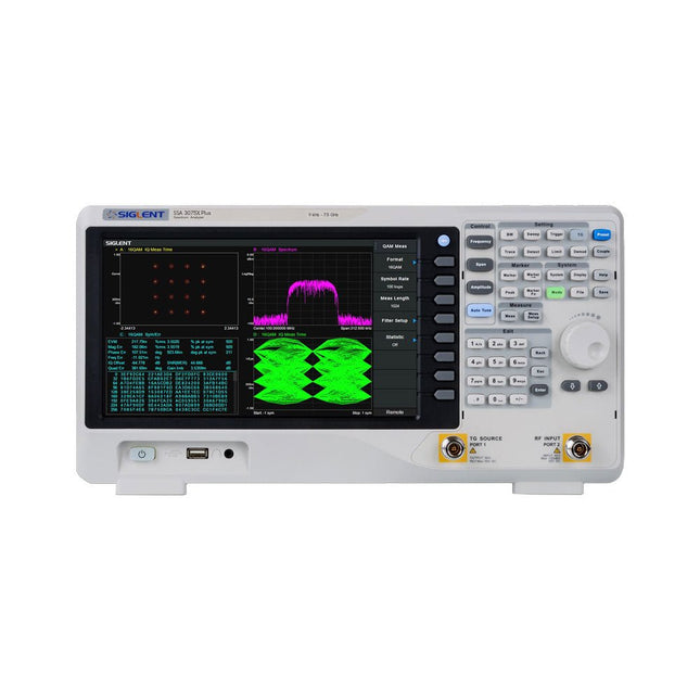
Siglent Siglent SSA3075X Plus Spectrum Analyzer (9 kHz – 7.5 GHz)
The Siglent SSA3075X Plus spectrum analyzer is a powerful and flexible tool for RF signal and network analysis. With a frequency range of 7.5 GHz, the analyzer delivers reliable automatic measurements and multiple modes of operation: spectrum analyzer the base, optional functions include RF power measurement, vector signal modulation analysis, reflection measurement, and EMI test. Applications include broadcast monitoring/evaluation, site surveying, S-parameter measurement, analog/digital modulation analysis, EMI pre-compliance test, research and development, education, production, and maintenance. Features Spectrum Analyzer Frequency Range from 9 kHz to 7.5 GHz –165 dBm/Hz Displayed Average Noise Level (Typ.) –98 dBc/Hz. @ 10 kHz Offset Phase Noise (1 GHz, Typ.) Level Measurement Uncertainty <0.7 dB (Typ.) 1 Hz Minimum Resolution Bandwidth (RBW) Preamplifier (Std.) Tracking Generator (incl. free of charge) Analog and Digital Signal Modulation Analysis Mode (opt.) Reflection Measurement Kit (opt.) EMI Filter and Quasi-Peak Detector Kit (opt.) Advanced Measurement Kit (opt.) 10.1-inch Multi-Touch Screen , Mouse and Keyboard supported Web Browser Remote Control on PC and Mobile Terminals and File Operation Specifications SSA3015X Plus SSA3021X Plus SSA3032X Plus SSA3075X Plus Frequency Range 9 kHz ~ 1.5 GHz 9 kHz ~ 2.1 GHz 9 kHz ~ 3.2 GHz 9 kHz ~ 7.5 GHz Resolution Bandwidth 1 Hz ~ 1 MHz 1 Hz ~ 1 MHz 1 Hz ~ 1 MHz 1 Hz ~ 3 MHz Phase Noise <–99 dBc/Hz <–98 dBc/Hz <–98 dBc/Hz <–98 dBc/Hz Total Amplitude Accuracy <1.2 dB <0.7 dB <0.7 dB <0.7 dB Display Average Noise Level –156 dBm/Hz –161 dBm/Hz –161 dBm/Hz –165 dBm/Hz Included Siglent SSA3075X Plus spectrum analyzer USB cable Power cord Quick start guide Downloads Datasheet Manual Documentation Firmware
€ 7.875,89
-

Elektor Digital Smart-Home- und IoT-Technik für den Arduino (PDF)
Smart-Home-Systeme selber bauen Smart Home- und IoT-Technik für den Arduino bietet eine Fülle von Praxisprojekten, die mit einem einzigen Kit aufgebaut werden können. Das "SunFounder Smart Home Internet of Things Kit V2.0 for Arduino" enthält über 30 Komponenten, Bauelemente und Module aus allen Bereichen der modernen Elektronik. Damit lassen sich eine Fülle von Projekten realisieren. Für den Einsteiger werden zunächst einige einfachere Einsteigerexperimente vorgestellt. Der fortgeschrittenere Anwender kann sich dagegen gleich an die komplexeren Themen heranwagen. Neben präzisen digitalen Thermometern, Hygrometern, Belichtungsmessern und verschiedenen Alarmanlagen entstehen auch praktisch einsetzbare Geräte und Anwendungen wie etwa eine vollautomatische Beleuchtungssteuerung ein digitales Thermostat eine multifunktionale Klimamessstation Zudem wird detailliert erklärt, wie Messdaten in das Internet übertragen werden. Dort sind sie grafisch darstellbar und können weltweit abgerufen werden. Auch auf die damit verbundenen Gefahren und die Problematik des Datenschutzes wird eingegangen. Die vorgestellten Praxisprojekte bleiben dabei aber nicht im Status eines „Laborprototyps“ stehen. Durch entsprechende Tipps und Hinweise entstehen vielmehr praxistaugliche Geräte, die in Haushalt, Hobby und Beruf eingesetzt werden können. Selbstverständlich können sämtliche Bauteile auch einzeln beschafft werden, so dass sich die Projekte im Buch auch ohne das komplette IoT-Kit durchführen lassen.
€ 29,80
Members: € 26,82
-
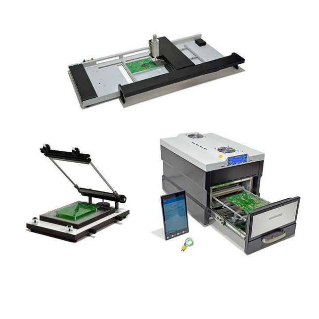
Paggen Werkzeugtechnik SMD Starter I – Production Line for Prototypes
The SMD Starter I prototype production line consists of the stencil printer TSD240, the SMD placement device PlaceMAN and the reflow oven 3LHR10. Stencil printer SD240 (+ Metal Squeegee 155 mm) Stencil size: max. 175 x 255 mm PCB size: max. 180 x 240 mm Size: 410 x 270 x 110 mm Weight: 6.7 kg incl. metal squeegee 155 mm incl. 8 magnets to hold the PCB, 6 of them with M3 grub screw Manual SMD pick-and-place device PlaceMAN for standard components incl. vacuum pump (without feeders, camera, monitor and dispenser) Equipped with smooth-running placement arm, placement head with one-hand operation, rotation of the Z-axis and automatic vacuum switch-off, incl. PCB holder, vacuum unit and 2 placement needles with rubber suction cups. Capacity of feeder (not included) 2x feeder cassette for 10 x 8 mm wheels left 4x feeder cassette for rod feeders for 5 rods each Further feeding systems are possible within the assembly area, e.g. strip-feeder plug-in system Dimensions Base unit (LxWxH): 765 x 390 x 210 mm With feeder cassette for 10 x 8 mm rolls (LxWxH): 765 x 390 x 210 mm With feeder cassette for 10 x 8 mm rolls and feeder cassette for rod feeder (LxWxH): 765 x 430 x 210 mm (height may vary due to rod length) With feeder cassette for 10 x 8 mm rolls incl. holder for 10 rolls and feeder cassette for rod feeder (LxWxH): 765 x 430 x 210 mm (height may vary due to rod length) Specifications Weight of basic unit: approx. 6 kg Axis travel (x,y,z): 470 x 230 x 15 mm Max. working area: 380 x 240 mm Max. PCB size: 230 x 360 mm Power supply: 230/12 V, 800 mA Power supply vacuum pump: 230 V, 6 W 3LHR10 Reflow Oven (programmable for lead-free soldering with manual drawer and tablet control) Reflow oven with IR and convection heating. Forced hot air convection ensures a uniform temperature profile throughout the chamber. After manually opening the door, the fans are turned on and the soldered PCB is quickly cooled. Small reflow oven with manual door Industry 4.0 ready, Bluetooth communication + tablet IR + convection heating Android application to connect to tablet or smartphone 100 different user programs Delivery content: 3LHR10, tablet with app, protective cover for tablet, 4 PCB holders, external thermocouple, manual at tablet Application Connect the oven to the power supply and connect the optionally available extraction system (3LFE10S) to the exhaust air nozzle. After the first turn on, the oven will search for a tablet or smartphone. When both are connected to the Android app, choose the programming of the oven. Here, programmable temperature and preheating time as well as temperature and other data are to be set. Register with the tablet to use the full scope of the software. If the oven is already programmed, the user can control the operation with buttons and display at the front panel. When the reflow process is complete, an audible signal sounds. A signal is also displayed on the tablet/smartphone. The drawer must now be opened manually. The Android application displays process status, time and temperature or other information. Specifications Power supply: 230 V, 50 Hz Maximum power: 3100 W Temperatures: 50-260°C Dimensions: 510 x 370 x 340 mm Maximum weight: 16 kg Grid dimensions: 350 x 220 mm Maximum dimensions of the printed circuit board: 300 x 200 mm Maximum component height on the PCB: 50 mm at the top, 30 mm at the bottom Scope of delivery Stencil printer TSD240 SMD placement device PlaceMAN Reflow oven 3LHR10
€ 6.549,00
Best Price
-

Elektor Digital Software Defined Radio (DE) | E-book
Schaltungen, Software und Empfangspraxis Die Kurzwellen-Empfangstechnik entwickelt sich ständig weiter. Im Mai 2007 wurde von Elektor das "Software Defined Radio mit USB-Schnittstelle" vorgestellt. Ziel war ein möglichst einfacher Empfänger, der durch den Einsatz geeigneter Software überzeugende Empfangsergebnisse liefert. Die benötigten Programme stehen auf der Elektor-Website und im Internet gratis zur Verfügung. Schon nach wenigen Monaten hatte dieser neue Empfänger eine weite Verbreitung gefunden. Zahlreiche Software-Autoren unterstützten das Projekt. Auch Bedienungshinweise, Erweiterungen sowie Tipps und Tricks findet man im Netz. Die Vielfalt der Möglichkeiten erschwert die Orientierung. Deshalb wurde dieses Buch geschrieben. Das Ziel ist ein Überblick über Aufbau, Software und Bedienung des SDR. Außerdem werden Selbstbauprojekte vorgestellt, die es erlauben, mit geringsten Kosten eigene Empfänger zu entwerfen; denn das Thema entwickelt sich laufend weiter...
€ 29,80
Members: € 26,82
-

Elektor Publishing Software Defined Radio zum Selbstbau
Praktischer Einstieg mit Arduino, GnuRadio und FPGA Das Thema „Software Defined Radio“ ist facettenreich: Neben der Schaltungstechnik ist auch eine Einarbeitung in die Programmierung von Hardware und PC wichtig. Ein schrittweises Vorgehen erleichtert Ihnen den Einstieg. Mit dem im Buch vorgestellten modularen „RF Bricks“-Konzept werden Sie zum Architekten Ihrer Signalkette. Auf einem Chassis angeordnet gewährleisten die Module einen soliden und gut abgeschirmten Aufbau, den Sie einfach verändern und mit eigenen Ideen anreichern können. Der skalierbare Aufbau bildet Ihr Blockschaltbild auch mechanisch ab – die so gewonnene Übersicht kann in der Aus- und Weiterbildung nützlich sein. Ein Arduino in Ihrem Chassis kommuniziert nach einigen Anpassungen mit üblichen SDR-Programmen, z. B. SDRCPP, GQRX und CubicSDR auf einer Linux-Plattform. Damit können Sie Ihren Empfänger direkt per Mausklick abstimmen. Wenn Sie Blockschaltbilder mögen, ist GnuRadio ein natürlicher Partner der „RF Bricks“. Mit einem selbst programmierten Python-Block gelingt Ihnen in GnuRadio die Fernsteuerung Ihres Empfängers. Im GnuRadio-Universum können Sie Ihre GUI stufenweise ausbauen, behalten dabei aber immer volle Kontrolle über die inneren Abläufe des Programms. Mit einem FPGA können zeitaufwändige Operationen auch direkt in die Hardware verlagert werden. Sie bauen stufenweise einen Doppelsuperhet auf und entwickeln die Filterkoeffizienten für FIR-Filter mit Scilab. Das in VHDL realisierte Weaver-Schema rundet diesen Empfänger ab, der mit hoher Empfindlichkeit und Dynamik aufwarten kann. Mit dem gewonnen Überblick und Ihrer neuen Hardware können Sie die einzelnen Aspekte des Themenkomplexes SDR beliebig weiter vertiefen. Downloads Software
€ 44,80
Best Price
-

Elektor Digital Software Defined Radio zum Selbstbau (PDF)
Praktischer Einstieg mit Arduino, GnuRadio und FPGA Das Thema „Software Defined Radio“ ist facettenreich: Neben der Schaltungstechnik ist auch eine Einarbeitung in die Programmierung von Hardware und PC wichtig. Ein schrittweises Vorgehen erleichtert Ihnen den Einstieg. Mit dem im Buch vorgestellten modularen „RF Bricks“-Konzept werden Sie zum Architekten Ihrer Signalkette. Auf einem Chassis angeordnet gewährleisten die Module einen soliden und gut abgeschirmten Aufbau, den Sie einfach verändern und mit eigenen Ideen anreichern können. Der skalierbare Aufbau bildet Ihr Blockschaltbild auch mechanisch ab – die so gewonnene Übersicht kann in der Aus- und Weiterbildung nützlich sein. Ein Arduino in Ihrem Chassis kommuniziert nach einigen Anpassungen mit üblichen SDR-Programmen, z. B. SDRCPP, GQRX und CubicSDR auf einer Linux-Plattform. Damit können Sie Ihren Empfänger direkt per Mausklick abstimmen. Wenn Sie Blockschaltbilder mögen, ist GnuRadio ein natürlicher Partner der „RF Bricks“. Mit einem selbst programmierten Python-Block gelingt Ihnen in GnuRadio die Fernsteuerung Ihres Empfängers. Im GnuRadio-Universum können Sie Ihre GUI stufenweise ausbauen, behalten dabei aber immer volle Kontrolle über die inneren Abläufe des Programms. Mit einem FPGA können zeitaufwändige Operationen auch direkt in die Hardware verlagert werden. Sie bauen stufenweise einen Doppelsuperhet auf und entwickeln die Filterkoeffizienten für FIR-Filter mit Scilab. Das in VHDL realisierte Weaver-Schema rundet diesen Empfänger ab, der mit hoher Empfindlichkeit und Dynamik aufwarten kann. Mit dem gewonnen Überblick und Ihrer neuen Hardware können Sie die einzelnen Aspekte des Themenkomplexes SDR beliebig weiter vertiefen. Downloads Software
€ 34,80
Members: € 31,32
-
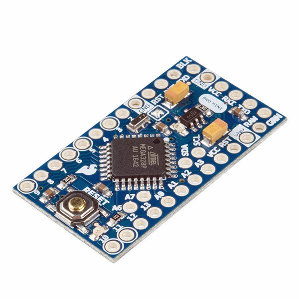
SparkFun SparkFun Arduino Pro Mini 328 (5 V, 16 MHz)
The Arduino Pro Mini is a microcontroller board based on the ATmega328P. It has 14 digital input/output pins (of which 6 can be used as PWM outputs), 6 analog inputs, an on-board resonator, a reset button, and holes for mounting pin headers. A six pin header can be connected to an FTDI cable or SparkFun breakout board to provide USB power and communication to the board. The Arduino Pro Mini is intended for semi-permanent installation in objects or exhibitions. The board comes without pre-mounted headers, allowing the use of various types of connectors or direct soldering of wires. The pin layout is compatible with the Arduino Mini. The Arduino Pro Mini was designed and is manufactured by SparkFun Electronics. Specifications Microcontroller ATmega328P Board Power Supply 5-12 V Circuit Operating Voltage 5 V Digital I/O Pins 14 PWM Pins 6 UART 1 SPI 1 I²C 1 Analog Input Pins 6 External Interrupts 2 DC Current per I/O Pin 40 mA Flash Memory 32 KB of which 2 KB used by bootloader SRAM 2 KB EEPROM 1 KB Clock Speed 16 MHz Dimensions 18 x 33.3 mm (0.7 x 1.3") Downloads Eagle files Schematics
€ 14,95€ 9,95Best Price
-

Speciale Elektor / E&M: 33 Progetti Top di Elettronica
Una ricca selezione di articoli dal Mondo Elektor! Gli articoli di questo libro sono una selezione accurata, il "meglio del meglio" di circuiti e progetti recenti, realizzati da tecnici di grande talento provenienti da tutto il mondo. Nel tipico stile di Elektor, questa raccolta offre qualcosa di interessante per tutti, dai progettisti esperti a coloro che praticano l'elettronica nel tempo libero. Sommario Super Servo TesterProva Fino a Quattro Servocomandi, Stand-Alone o in Sistema The TubeUn Insolito Amplificatore a Valvole Cloc 2.0La Sveglia che Avete Sempre Desiderato Stazione Meteo LoRa Low-PowerCostruitevi una Stazione Meteorologica “Long Range” Uscita Video con Microcontrollori (Parte 1)Video Composito Uscita Video con Microcontrollori (Parte 2)Uscita VGA e DVI Un Raspberry Pi Pico come Analizzatore di SpettroFFT su Base Hardware a Basso Costo PIC O’Clock – In Contatto col TempoProgettare un Ricevitore di Segnali Orari SDR Frequenzimetro di Rete ACMisura Frequenza e Tensione della Rete Elettrica Generatore di Funzioni con Arduino NanoNano + Codice = Generatore di Funzioni Monitor CO2Un Approccio Fai-Da-Te per Il Controllo della Qualità dell‘Aria ChatMagLevLa Levitazione Magnetica con AI Alimentatore Lineare Variabile Combinato0…50 V / 0…2 A con Struttura Simmetrica Duale Ricevitore Digitale FM con Arduino e TEA5767Restate in Ascolto con un Arduino Nano Protezione Antigelo per Piante da FruttoCon Registrazione della Temperatura Carico Elettronico con Generatore di clock IntegratoPer Collaudare Alimentatori, Convertitori di Tensione e Batterie 128 Termostato Web con ESP32Mantieni il Vino alla Giusta Temperatura Iniezione di Segnali e di Potenza......per Rilevare le Interruzioni nei Cavi DIY LiPo Supercharger KitDal Prototipo al Mercato di Massa Livella Digitale con Stroboscopio AttivoCalibra il Tuo giradischi con Questo Strumento "Tutto-in-Uno" The Game of Life – 262.144 Modi di GiocareDal Progetto di un Lettore Rilevatore di PerditeCollegato ad Arduino Cloud Orologio di LissajousL’Incedere del Tempo con le Figure di Lissajous Mastermind – Controllato da ArduinoUna Versione Moderna del Classico Gioco di Decifrazione Generatore Audio Analogico 1 kHzOnda Sinusoidale a Bassa Distorsione Aggiorna il tuo Caricabatteria (Parte 1)Non Buttarlo, Modificalo! Aggiorna il tuo Caricabatteria (Parte 2)Non Buttarlo, Modificalo! Sistemi GNSS RTK a Basso CostoCon Accuratezza a Livello Centimetrico Esperimenti a 10 GHz con LNB Satellitari ModificatiSbloccare la Banda X a Basso Costo Telecamera per FerromodellismoInstalla un Modulo ESP32 CAM a Bordo! Monitor di Tensione con MicrocontrolloreProtezione dalla Scarica Profonda per Batterie e Altro Nodo Sensore AutonomoTrasmissione Dati LoRa con Alimentazione a Batterie Solari Layout e Sicurezza sul PCBConsigli per un Progetto Sicuro e Durevole
€ 29,95
Members: € 26,96
-

Elektor Digital Speciale Elektor / E&M: 33 Progetti Top di Elettronica (PDF)
Una ricca selezione di articoli dal Mondo Elektor! Gli articoli di questo libro sono una selezione accurata, il "meglio del meglio" di circuiti e progetti recenti, realizzati da tecnici di grande talento provenienti da tutto il mondo. Nel tipico stile di Elektor, questa raccolta offre qualcosa di interessante per tutti, dai progettisti esperti a coloro che praticano l'elettronica nel tempo libero. Sommario Super Servo TesterProva Fino a Quattro Servocomandi, Stand-Alone o in Sistema The TubeUn Insolito Amplificatore a Valvole Cloc 2.0La Sveglia che Avete Sempre Desiderato Stazione Meteo LoRa Low-PowerCostruitevi una Stazione Meteorologica “Long Range” Uscita Video con Microcontrollori (Parte 1)Video Composito Uscita Video con Microcontrollori (Parte 2)Uscita VGA e DVI Un Raspberry Pi Pico come Analizzatore di SpettroFFT su Base Hardware a Basso Costo PIC O’Clock – In Contatto col TempoProgettare un Ricevitore di Segnali Orari SDR Frequenzimetro di Rete ACMisura Frequenza e Tensione della Rete Elettrica Generatore di Funzioni con Arduino NanoNano + Codice = Generatore di Funzioni Monitor CO2Un Approccio Fai-Da-Te per Il Controllo della Qualità dell‘Aria ChatMagLevLa Levitazione Magnetica con AI Alimentatore Lineare Variabile Combinato0…50 V / 0…2 A con Struttura Simmetrica Duale Ricevitore Digitale FM con Arduino e TEA5767Restate in Ascolto con un Arduino Nano Protezione Antigelo per Piante da FruttoCon Registrazione della Temperatura Carico Elettronico con Generatore di clock IntegratoPer Collaudare Alimentatori, Convertitori di Tensione e Batterie 128 Termostato Web con ESP32Mantieni il Vino alla Giusta Temperatura Iniezione di Segnali e di Potenza......per Rilevare le Interruzioni nei Cavi DIY LiPo Supercharger KitDal Prototipo al Mercato di Massa Livella Digitale con Stroboscopio AttivoCalibra il Tuo giradischi con Questo Strumento "Tutto-in-Uno" The Game of Life – 262.144 Modi di GiocareDal Progetto di un Lettore Rilevatore di PerditeCollegato ad Arduino Cloud Orologio di LissajousL’Incedere del Tempo con le Figure di Lissajous Mastermind – Controllato da ArduinoUna Versione Moderna del Classico Gioco di Decifrazione Generatore Audio Analogico 1 kHzOnda Sinusoidale a Bassa Distorsione Aggiorna il tuo Caricabatteria (Parte 1)Non Buttarlo, Modificalo! Aggiorna il tuo Caricabatteria (Parte 2)Non Buttarlo, Modificalo! Sistemi GNSS RTK a Basso CostoCon Accuratezza a Livello Centimetrico Esperimenti a 10 GHz con LNB Satellitari ModificatiSbloccare la Banda X a Basso Costo Telecamera per FerromodellismoInstalla un Modulo ESP32 CAM a Bordo! Monitor di Tensione con MicrocontrolloreProtezione dalla Scarica Profonda per Batterie e Altro Nodo Sensore AutonomoTrasmissione Dati LoRa con Alimentazione a Batterie Solari Layout e Sicurezza sul PCBConsigli per un Progetto Sicuro e Durevole
€ 24,95
Members: € 22,46
-

Elektor Digital Sprachsteuerung von IoT-Projekten mit Amazon Alexa (PDF)
Sprachsteuerung von IoT-Projekten mit Amazon Alexa gibt dem Leser einen tiefen Einblick in die Technik der Sprachsteuerung am Beispiel von Amazon Alexa. Es erklärt detailliert Schritt für Schritt, wie man Raspberry Pi, ESP8266/32 und Arduino mit einem Sprachassistenten verbindet und steuert. Dieses geschieht anhand von Projekten aus den Bereichen Hausautomation und Robotik. Der Leser erfährt, wie man Heizkessel, Roboter und Gartenhäuser mit dieser modernen Mensch-Maschine-Schnittstelle kommandieren kann. Der Autor Walter Trojan führt dabei den Leser in die vielschichtige Welt der Amazon Web Services ein, wo er neben dem Alexa Skills Kit weitere Module wie AWS Lambda und IoT Core kennenlernt. Das erwartet den Leser: Kapitel 1: Sprachassistenten setzen sich durch Kapitel 2: Alexa intern Kapitel 3: Der erste Alexa Skill Kapitel 4: Alexa Skills für Fortgeschrittene Kapitel 5: Erster Hardware-Skill auf Raspberry Pi Kapitel 6: Auch Alexa liebt die Arduino-IDE Kapitel 7: Hacks mit Schaltern Kapitel 8: Alexa steuert ein Gartenhaus Kapitel 9: Auch Roboter gehorchen Alexa Kapitel 10: Alexa geht fremd
€ 32,80
Members: € 29,52
-

Elektor Digital SPS-Programmierung mit dem Raspberry Pi und dem OpenPLC-Projekt (PDF)
Einführung in die SPS-Programmierung mit dem Open-Source-Projekt auf dem Raspberry Pi und Modbus-Beispiele mit dem Arduino Uno und ESP8266 Die SPS-Programmierung ist heute in der Industrie und in der Hausautomation sehr weit verbreitet. In diesem Buch beschreibt der Autor, wie der Raspberry Pi 4 als SPS eingesetzt werden kann. Angefangen mit der Softwareinstallation auf dem Raspberry Pi und dem SPS-Editor auf dem PC geht es nach einer Beschreibung der Hardware an das Programmieren. Es folgen interessante Beispiele nach IEC 61131-3 in den verschiedenen Programmiersprachen. Ausführlich wird auch erklärt, wie der SPS-Editor benutzt wird und wie die Programme auf den Raspberry Pi geladen und ausgeführt werden. Angefangen mit der Programmierung mit KOP (Kontaktplan) über ST (Structured Control Language) bis zu AS (Special Function Chart) werden alle IEC-Sprachen mit Beispielen behandelt. Diese können auf der Website des Autors heruntergeladen werden. Auch die Vernetzung kommt nicht zu kurz. Der Arduino Uno und der ESP8266 werden als ModbusRTU- bzw. ModbusTCP-Module programmiert, um Zugriff auf externe Peripherie zu erhalten. Damit ist es möglich, Sensoren einzulesen und Verbraucher zu schalten. Interessant dürften auch E/A-Schaltungen sein, die dem 24V-Industriestandard entsprechen. Befehlsübersichten für ST und KOP runden das Buch ab. Nach dem Durcharbeiten des Buches ist der Leser in der Lage, eigene SPS-Steuerungen mit dem Raspberry Pi zu verwirklichen.
€ 32,80
Members: € 29,52
-

Elektor Digital Starten met Internet of Things (E-book)
35 projecten met Raspberry Pi en wireless Arduino Internet of Things (alles aan het internet) is een trend die zich niet meer laat keren. We willen alles in huis met onze mobiel of tablet doen, van Facebook tot TV kijken, van lichten bedienen tot de temperatuur in de gaten houden. In dit boek laten we in 35 leuke en handige projecten zien hoe u op eenvoudige wijze zelf een Internet of Things systeem kunt aanleggen. We gaan in op de hardware (de perfecte combinatie van Raspberry Pi en Arduino) en de software om bediening via internet mogelijk te maken. We maken gebruik van Wi-Fi en radioverbindingen zodat er geen kabels dwars door uw huis hoeven. Wanneer u deze projecten maakt heeft u een compleet Internet of Things systeem waarmee u van alles in uw huis kunt bedienen en bekijken. Bijvoorbeeld of er post in de brievenbus ligt en of de auto in de garage staat. U kunt op vanaf de bank het licht aandoen en het alarm bedienen. Door de heldere uitleg kunt u de projecten eenvoudig aanpassen om bijvoorbeeld uw koffiezetautomaat of tv op afstand aan te zetten. Via de index vindt u gemakkelijk creatieve projecten die als voorbeeld kunnen dienen, zodat u zelfstandig alles met het internet kunt verbinden.
€ 29,95
Members: € 26,96
-

Elektor Digital Stromversorgung ohne Stress 2 (PDF)
Aus der Reihe "Stromversorgung ohne Stress" (Band 2) Anwendungen, Applikationen und Bauanleitungen Eines haben alle elektronischen Schaltungen und Geräte gemeinsam: Ihre Funktion steht und fällt mit der Stromversorgung. Schon deshalb muss man dieser Baugruppe besondere Aufmerksamkeit widmen. Beschäftigte sich Band 1 mit den Grundlagen und Schaltungen der Stromversorgungstechnik für elektronische Geräte aus der Praxis, bietet der zweite Band neben direkt verwertbaren Grundlageninformationen eine Sammlung verschiedener praktischer Anleitungen und Applikationen sowie Bauanleitungen. Damit ist das Buch für jeden ambitionierten Elektronik-Praktiker eine wertvolle Bereicherung seiner Gestaltungsmöglichkeiten. Aus dem Inhalt: Kapitel 1 • Messungen an Spannungs- und Stromquellen Kapitel 2 • Mobile Spannungs- und Stromquellen Kapitel 3 • Netzbetriebene Versorgungsgeräte Kapitel 4 • Verschiedene Themen zur Stromversorgung, unter anderem auch zur drahtlosen Energieübertragung
€ 32,80
Members: € 29,52
-

Elektor Digital Stromversorgungen in der Praxis (PDF)
Stromversorgungen in der Praxis (E-book)
€ 39,80
Members: € 35,82
-

Elektor Digital Supersnel PC Interfacen (E-book)
Wilt u in enkele minuten een programma maken op uw PC, dat communiceert met een microcontroller? Dit boek, samen met de Piccolino en gratis software, maakt dat mogelijk! Als hardware wordt gebruik gemaakt van de Piccolino. Dit is een prototype platform met een moderne PIC16F887 microcontroller, dat gebruikt kan worden om razendsnel microcontroller opstellingen te maken. Alle basisvoorzieningen zijn aanwezig op de Piccolino, en door middel van de headers kunnen extra onderdelen eenvoudig aangesloten worden. De Piccolino wordt geprogrammeerd met de krachtige maar eenvoudig te leren gratis programmeertaal JAL. Deze taal wordt zowel door hobbyisten als professionals gebruikt. Bovendien is een serie projectboeken in deze taal verkrijgbaar, en een lesboek waarmee u JAL kunt leren. Aan de PC kant wordt gebruik gemaakt van de eveneens eenvoudig te leren gratis programmeertaal Small Basic van Microsoft. Deze taal is speciaal ontwikkeld om snel Windows programma's te kunnen ontwikkelen, ook voor mensen die weinig of geen PC programmeer ervaring hebben. U leert verschillende technieken om een PC met een microcontroller te laten communiceren zoals losse communicatie, het versterken en verzwakken van signalen, verwerken van valse metingen, master-slave communicatie en synchronisatie met geforceerde reset. Behalve theorie staan in het boek ook 15 leuke en praktische projecten. Door de duidelijke uitleg en instructies kunt u deze projecten zelf uitbreiden en helemaal aan uw eigen wensen aanpassen. Een paar voorbeelden uit het boek: Meet signalen en toon ze op de PC Maak een eigen muis of keyboard besturing. Meet en analyseer componenten (Spoel / Condensator / Transistor / OPAMP) met automatische grafieken op uw PC. Bestuur een servomotor vanaf de PC. Verzamel metingen in de Piccolino en zet ze later over naar uw PC. De combinatie van theorie en praktijkvoorbeelden in dit boek zorgt er voor dat u voor elk interface-probleem een oplossing bij de hand hebt, of weet hoe u er een moet maken.
€ 29,95
Members: € 26,96
-

Elektor Digital Systemprogrammierung für AVR-Mikrocontroller (E-book)
Systemprogrammierung für AVR-Mikrocontroller (E-book)
€ 39,80
Members: € 35,82
-

Elektor Digital Technical Modeling with OpenSCAD (E-book)
Create Models for 3D Printing, CNC Milling, Process Communication and Documentation Engineers dread designing 3D models using traditional modeling software. OpenSCAD takes a refreshing and completely different approach. Create your models by arranging geometric solids in a JavaScript-like language, and use them with your 3D printer, CNC mill, or process communication. OpenSCAD differs from other design systems in that it uses programmatical modeling. Your model is made up of primitives that are invoked using a C-, Java- or Python-like language. This approach to model design is close to the “mechanical work” done in the real world and appeals to engineers and others who are not a member of the traditional creative class. OpenSCAD also provides a wide variety of comfort functions that break the 1:1 relationship between code and geometry. This book demonstrates the various features of the programming language using practical examples such as a replacement knob for a LeCroy oscilloscope, a wardrobe hanger, a container for soap dispensers, and various other real-life examples. Written by an engineer with over 15 years of experience, this book is intended for Linux and Windows users alike. If you have programming experience in any language, this book will have you producing practical three-dimensional objects in short order!
€ 29,95
Members: € 26,96
-

Elektor Digital Technisches Konstruieren mit OpenSCAD (PDF)
Modelle für 3D-Druck, CNC-Fräsen, Prozesskommunikation und Dokumentation erstellen Das Design dreidimensionaler Modelle mit Werkzeugen wie Blender oder 3D Studio Max ist eine Aufgabe, die ingenieurwissenschaftlich begabte Personen nur allzu gern delegieren. OpenSCAD wählt einen erfrischend anderen Zugang. Anstatt ein Objekt als Punktwolke zu betrachten, schreibt der Modellerzeuger in einer an JavaScript erinnernden Sprache ein Programm. Dieses beschreibt die zu erzeugende Geometrie als eine Serie von Arbeitsschritten. Dreidimensionale Modelle entstehen so in einem Workflow, der an die Entwicklung klassischer ingenieurwissenschaftliche Güter erinnert. Wegen der Nähe zur manuellen Fertigung mit Werkzeug ist das ein Prozess, der Ingenieuren gut in die Hände spielt. Aber Achtung: trotz der Einfachheit der Syntax ist OpenSCAD kein primitives Modellierungsprogramm. Umfangreiche Scriptingmöglichkeiten sorgen dafür, dass sich die Modelle dynamisch an geänderte Situationen anpassen. Dieses Lehrbuch demonstriert die Möglichkeiten von OpenSCAD anhand praktischer Beispiele. Freuen Sie sich auf Ersatzknöpfe für ein LeCroy-Oszilloskop, Garderobenstangenhalter, einen Halter für Seifenspender und diverse andere Beispiele aus dem realen Leben. Der mit mehr als 15 Dienstjahren Erfahrung ausgestattete Autor entwickelte dieses für Linux und Windows gleichermaßen geeignete Buch explizit für informatikaffine Personen. Wenn Sie mit irgendeiner Programmiersprache Erfahrung haben, ist dieses Buch ihr Weg zum schnellen und unbürokratischen Erzeugen dreidimensionaler Modelle.
€ 29,80
Members: € 26,82
-

Elektor Publishing Tektronix 7000 Series Mainframes
The Most Iconic Oscilloscopes in Electronics History The 7000 Series was the most iconic family of oscilloscopes in the history of technology. Introduced in 1969 by Tektronix, the sector’s leader at the time, this remarkable line of instruments defined an era and became a benchmark for generations of engineers, researchers, and technicians. Throughout the 1970s and well beyond, 7000-Series oscilloscopes were a constant presence in laboratories, universities, and industrial facilities around the world. Their modular plug-in architecture, exceptional flexibility, and outstanding performance embodied the engineering philosophy that made Tektronix synonymous with accuracy, innovation, and reliability. This book offers an in-depth exploration of the 7000-Series oscilloscopes, combining historical context, technical analysis, and practical insight into their design and restoration. Conceived as a continuation of Tektronix Epic Oscilloscopes, this work expands the subject into two volumes: the first devoted to mainframes and core technologies, the second focused entirely on plug-ins.
€ 69,95€ 54,95Best Price


