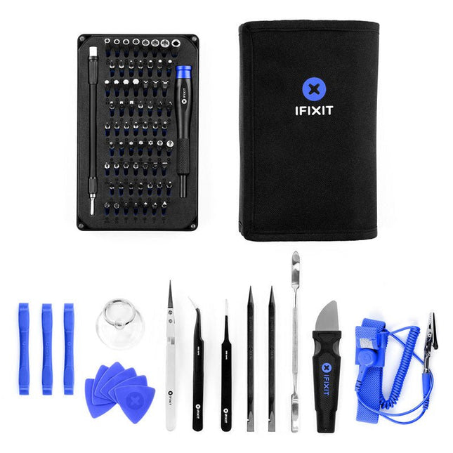
The Pro Tech Toolkit is the one thing every DIYer, fixer, hacker, hobbyist, and professional needs to tackle any job.
Every tool in the Pro Tech Toolkit has been re-engineered to be better. From the 64 Bit Driver Kit to the iFixit Opening Picks, every tool is specially designed and selected to maximize your repair capabilities.
At the core of this kit is the iFixit 64 Bit Driver Kit, designed with extensive research into what fastener types are currently used in the consumer electronics industry and which legacy fasteners are still in demand by consumers. From the Apple Watch with its new tiny Tri-Point screws to vintage Nintendo game consoles with gamebit fasteners, the 64 bit kit covers them all with the highest quality CNC machined bits. Even the sturdy case was carefully engineered, having no hinges or latches to break, and features a sorting tray inside the magnetically attached lid.
High-Performance Toolkit for DIY Repairs
The perfect toolkit for pros to average joes.
Contains all the poking, prying, gripping, lifting, ESD safety, and screw driving tools needed to service consumer electronics.
Completely re-engineered to provide all the tools that you need, and none that you don't.
Included
Anti-Static Wrist Strap – protection for circuits against static electricity
Small Suction Handle – suction handle for holding onto things lacking handles
3x iFixit Opening Tool – soft plastic prying tools
6x iFixit Opening Picks – thin prying tool for opening electronic devices
Nylon Tipped Reverse Tweezers – to elevate and hold your work
Angled ESD Tweezers – ESD-safe, feature teeth for tougher grip
Blunt ESD Tweezers – ESD-safe, feature teeth for tougher grip
Standard Spudger – tough antistatic tool for a variety of purposes
Halberd Spudger – features a hook for scooping, scraping, pulling, and guiding.ESD-safe.
Metal Spudger – for more powerful prying, scraping, probing, and poking action
Jimmy – handy tool for 'Jimmy'ing open electronics.
Magnetic Pad – Holds tiny screws and parts during repairs
Tool Roll – Durable and compact
Mako Precision Bit Set – all the bits needed for repairs on small electronics
Mako Precision Bit Set Includes
64 Bit Driver
150 mm Flex Extension
4 mm Screwdriver Bits
Phillips – 000, 00, 0, 1, 2
Flathead – 1, 1.5, 2, 2.5, 3, 4 mm
Torx – T2, T3, T4, T5
Torx Security – TR6, TR7, TR8, TR9, TR10, TR15, TR20, TR25
Pentalobe – P2, P5, P6
JIS – J000, J00, J0, J1
Hex – 0.7, 0.9, 1.3, 1.5, 2, 2.5, 3, 3.5, 4, 4.5, 5 mm
Tri-point – Y000, Y00, Y0, Y1
Nut Driver – 2.5, 3, 3.5, 4, 4.5, 5, 5.5 mm
Square – 1, 2
Gamebit – 3.8, 4.5 mm
Spanner – 6, 8
Triangle – 2, 3 mm
Standoff Bit for iPhone
Oval Bit
Magnetic Pickup Bit
SIM Eject Bit
1/4" to 4 mm Driver Adapter
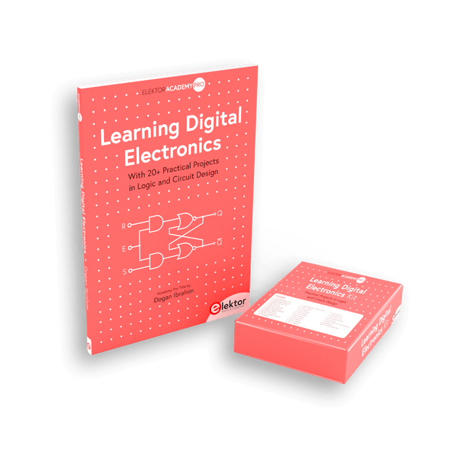
Master digital electronics – the hands-on way!
This bundle includes the book Learning Digital Electronics, featuring 20+ practical projects in Logic and Circuit design, as well as a 100-piece kit – so you can start building logic circuits, counters, displays, and more right away.
Learning Digital Electronics (Book)
This book is a practical guide to digital electronics, covering the essential components of modern digital systems: number systems, logic gates, Boolean algebra, combinational and sequential logic, and more.
Through more than 20 structured projects, you’ll design and build digital systems using real-world components such as logic gates, multiplexers, decoders, flip-flops, counters, and shift registers. The projects range from basic LED logic circuits to digital locks, display systems, traffic light controllers, and timing-based designs.
Selected projects introduce the use of tools such as CircuitVerse for circuit simulation, while several designs make use of 74HC-series logic devices, commonly used in digital hardware prototyping.
Inside, you’ll find:
Clear coverage of number systems and binary arithmetic
Logic gate fundamentals and universal gate implementations
Step-by-step projects using flip-flops, counters, and registers
Real-world design with 74HC-series logic chips
Techniques for designing combinational and sequential systems
This book takes a design-first, application-driven approach to digital electronics—built around working circuits, tested logic, and hands-on experimentation.
Learning Digital Electronics (Kit)
This kit has been specially developed to complement the book "Learning Digital Electronics". Since all necessary components are included, you can complete every practical project in the book directly.
Kit contents
2x 74HC08 AND gate chip
2x 74HC00 NAND gate chip
1x 74HC86 XOR gate chip
1x 555 timer chip
1x 74HC161 counter chip
1x 74HC164 shift register
1x CD4511 7-segment decoder
1x CD4027 JK flip-flop
1x BC337 NPN transistor
1x KPS-5161 7-segment common-cathode display
1x Light dependent resistor (LDR)
4x 10 KΩ resistors
8x 1 KΩ resistor
2x 47 KΩ resistors
1x 100 KΩ resistor
4x 2.7 KΩ resistors
1x 5.6 KΩ resistor
1x 150 KΩ resistor
1x 10 μF capacitor
2x 0.01 μF capacitor
2x 100 nF capacitor
8x Small red LED
1x Small green LED
1x Small orange LED
4x Pushbutton switches
1x Active buzzer
1x Battery holder for 3x AA batteries (batteries not included)
1x Breadboard
40x Male-to-male jumper wires (length: 200 mm)
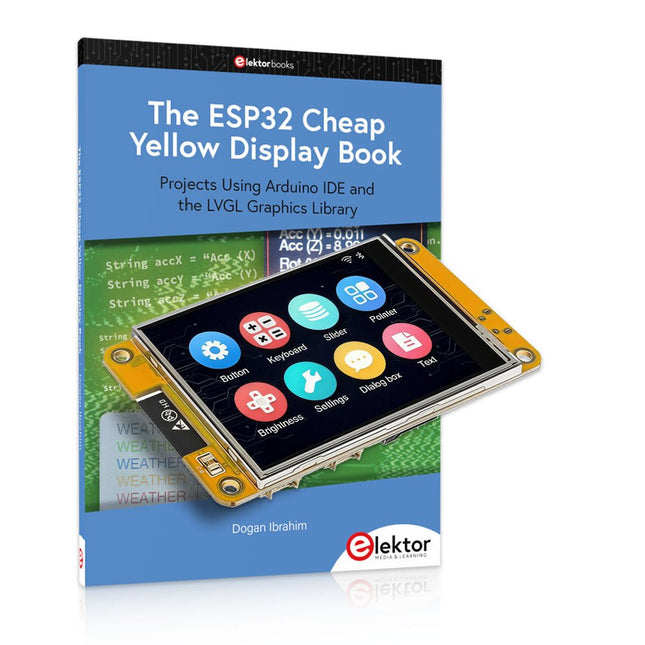
Over 40 Fully Tested ESP32 Projects Using Arduino IDE and the LVGL Graphics Library
This bundle includes the ESP32 Cheap Yellow Display (CYD) – a compact development board combining a standard ESP32 microcontroller with a 320x240 pixel TFT color display. The board also features multiple connectors for GPIO, serial communication (TX/RX), power, and ground. The built-in display is a major advantage, allowing users to create complex, graphics-based projects without the need for external LCDs or displays.
The accompanying book introduces the CYD board's hardware and on-board connectors in detail. It provides a range of beginner to intermediate-level projects developed using the popular Arduino IDE 2.0. Both basic graphics functions and the powerful LVGL graphics library are covered, with practical projects illustrating each approach.
All included projects have been fully tested and are ready to use. The book provides block diagrams, circuit schematics, complete code listings, and step-by-step explanations. With the LVGL library, readers can create modern, full-color graphical interfaces using widgets such as buttons, labels, sliders, calendars, keyboards, charts, tables, menus, animations, and more.
ESP32 Cheap Yellow Display Board
This development board (also known as "Cheap Yellow Display") is powered by the ESP-WROOM-32, a dual-core MCU with integrated Wi-Fi and Bluetooth capabilities. It operates at a main frequency of up to 240 MHz, with 520 KB SRAM, 448 KBROM, and a 4 MB Flash memory. The board features a 2.8-inch display with a resolution of 240x320 and resistive touch.
Furthermore, the board includes a backlight control circuit, touch control circuit, speaker drive circuit, photosensitive circuit, and RGB-LED control circuit. It also provides a TF card slot, serial interface, DHT11 temperature and humidity sensor interface, and additional IO ports.
The module supports development in Arduino IDE, ESP-IDE, MicroPython, and Mixly.
Applications
Image transmission for Smart Home device
Wireless monitoring
Smart agriculture
QR wireless recognition
Wireless positioning system signal
And other IoT applications
Specifications
Microcontroller
ESP-WROOM-32 (Dual-core MCU with integrated Wi-Fi and Bluetooth)
Frequency
Up to 240 MHz (computing power is up to 600 DMIPS)
SRAM
520 KB
ROM
448 KB
Flash
4 MB
Operating voltage
5 V
Power consumption
approx. 115 mA
Display
2.8-inch color TFT screen (240 x 320)
Touch
Resistive Touch
Driver chip
ILI9341
Dimensions
50 x 86 mm
Weight
50 g
Downloads
GitHub
This bundle contains:
The ESP32 Cheap Yellow Display Book (normal price: €35)
ESP32 Cheap Yellow Display Board (normal price: €25)
1x ESP32 Dev Board with 2.8" Display and acrylic Shell
1x Touch pen
1x Connector cable
1x USB cable
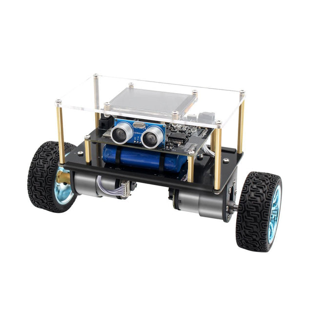
Arduino-compatible, ESP32-controlled, 2-wheeled Balancing Robot
The Elektor Mini-Wheelie is an experimental autonomous self-balancing robot platform. Based on an ESP32-S3 microcontroller, the self-balancing robot is fully programmable using the Arduino environment and open-source libraries. Its wireless capabilities allow it to be controlled remotely over Wi-Fi, Bluetooth or ESP-NOW or to communicate with a user or even another robot.
An ultrasonic transducer is available for detecting obstacles. Its color display can be used for displaying cute facial expressions or, for the more down-to-earth users, cryptic debug messages.
The robot comes as a neat kit of parts that you must assemble yourself. Everything is included, even a screwdriver.
Note: The Mini-Wheelie is an educational development platform intended for learning, experimentation, and robotics development. It is not classified as a toy for children, and its features, documentation, and intended audience reflect this purpose. The product is aimed at students, educators, and developers who wish to explore robotics, programming, and hardware integration in an educational setting.
Specifications
ESP32-S3 microcontroller with Wi-Fi and Bluetooth
MPU6050 6-axis Inertial Measurement Unit (IMU)
Two independently controlled 12 V electric motors with tachometer
Ultrasonic transducer
2.9" TFT color display (320 x 240)
MicroSD card slot
Battery power monitor
3S rechargeable Li-Po battery (11.1 V/2200 mAh)
Battery charger included
Arduino-based open-source software
Dimensions (W x L x H): 23 x 8 x 13 cm
Included
1x ESP32-S3 Mainboard + MPU6050 module
1x LCD board (2.9 inch)
1x Ultrasonic sensor
1x Battery pack (2200 mAh)
1x Battery charger
1x Motor tyre kit
1x Case board
1x Acrylic board
1x Screwdriver
1x Protective strip
1x Flex cable B (8 cm)
1x Flex cable A (12 cm)
1x Flex cable C
4x Copper column A (25 mm)
4x Copper column B (55 mm)
4x Copper column C (5 mm)
2x Plastic nylon column
8x Screws A (10 mm)
24x Screws B (M3x5)
8x Nuts
24x Metal washers
2x Zip tie
1x MicroSD card (32 GB)
Downloads
Documentation
This kit includes iFixit's widest assortment of bits, complete with every driver head you’ll need to tackle any repair or DIY project. It includes standard bits like Phillips and Flathead in a full range of sizes to handle everything from precision electronics repair to home DIY projects. And it wouldn’t be an iFixit bit set if it didn’t include all the exotic bits from Pentalobes for Apple iPhone and MacBook repair to Gamebits for your vintage Nintendo consoles.
All of the next-gen bit sets have been re-designed in order to maximize convenience and usability. The bit set lid is held in place with magnets to increase product lifespan (no more broken hinges or clasps) and also mounts to the back of the bit set case to keep it out of the way while you do your work. If you need help keeping your screws and parts organized, you can use the lid’s integrated sorting tray. The 4 mm bits have been adjusted and have now a longer neck for a deeper and more precise reach.
Toolkit Includes
Easy-to-Open Magnetized Case
Lid with Built-in Sorting Tray
4 mm Aluminum Bit Driver
1/4' Aluminum Bit Driver
4 mm Screwdriver Bits
Phillips - 000, 00, 0
Flathead - 1, 1.5, 2, 2.5, 3, 3.5 mm
Torx - T2, T3, T4, T5
Torx Security - TR6, TR7, TR8
Pentalobe - P2, P5, P6
JIS - 000, 00, 0, 1
Hex - 0.7, 0.9, 1.3, 1.5 mm
Hex Security - 2, 2.5, 3, 3.5 mm
Tri-point - Y000, Y00, Y0, Y1
Nut driver - 2.5, 3, 3.5, 4, 4.5, 5, 5.5 mm
Gamebit - 3.8, 4.5 mm
Spanner - 4, 6
Triangle - 2, 2.2, 2.6, 3 mm
Oval Bit
iPhone Standoff Bit
Sim Eject Bit
Magnetic Pickup Bit
1/4' Screwdriver Bits
Phillips - 1, 2, 3
Flathead - 4, 5, 6, 7, 8 mm
Hex Security - 4, 5, 6, 7, 8 mm
Hex Security SAE - 1/8, 9/64, 5/32, 3/16, 7/32, 1/4
Pozidriv - PZ0, PZ1, PZ2, PZ3
Torq-set - 6, 8, 10
Spanner - 8, 10, 12
Square - 0, 1, 2, 3
Spline - M5, M6, M8
Torx Security - TR9, TR10, TR15, TR20, TR25, TR27, TR30, TR35, TR40
Tri-wing 1, 2, 3, 4
Clutch 1, 2, 3
Schrader Valve
Hook Drive
1/4' to 4 mm Adapter
1/4' Driver to 1/4' Socket
1/4' Driver to 3/8' Socket
1/4' Socket to 1/4' Driver
Specifications
Bit Metal: 6150 Steel
Driver Material: Anodized Aluminum
Case Material: ABS
Foam: EVA
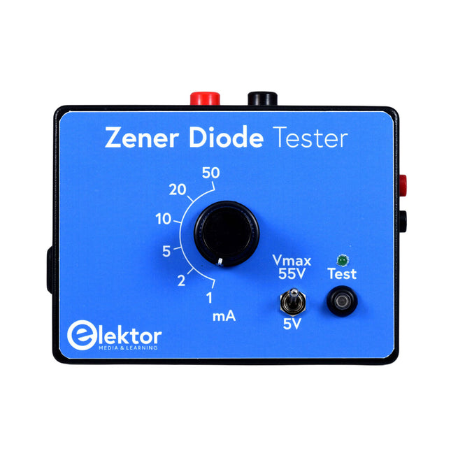
The Elektor Zener Diode Tester is essentially a constant-current source that can be switched in steps from 1 to 50 mA. It can be used to test Z-diodes up to a maximum of 54 V. Thanks to a 60-V step-up converter, the device can be powered by the usual 5 to 12 V.
The principle of this tester is straightforward. A Z-diode or other DUT (device under test, such as an LED) is biased by an adjustable current source. The voltage across the DUT can be measured with a multimeter. The voltage of most (small) Z-diodes is specified at a current of 5 mA. Depending on the application, the voltage at other currents can also be of interest. That is why six current settings are available: 1, 2, 5, 10, 20, and 50 mA. LEDs are often specified at a current of 20 mA.
What can be tested is:
Whether a Z-diode is defective (short circuit or high impedance).
Whether a Z-diode exhibits the correct Z-voltage.
How a Z-voltage changes with different currents.
What exact voltage is present at an integrated voltage reference.
Whether LEDs in a series chain differ in brightness (hence the 20 mA current).
What the current gain is for different base currents in (power) transistors.
The kit contains all parts listed in the bill of materials including PCB and enclosure.
Specifications
Supply voltage
5…12 V/2 A (USB-C)
Supply current (Itest = 50 mA)
1.1 A @ 5 V / 412 mA @ 12 V
Selectable currents
1, 2, 5, 10, 20, and 50 mA
Max. test voltage
>54 V @ Itest ≥1 mA
Max. output voltage
60 V @ Itest = 0 mA
Voltage limit at 5 V
4.5 V @ Itest = 1 mA / 5.18 V @ Itest = 50 mA
Enclosure dimensions
110 x 82 x 44 mm
PCB size
105.4 x 67.3 mm
Connections
4 mm banana sockets for multimeter
2 mm banana sockets for test clips
USB-C socket for power supply
Included
Resistors
R1 = 3.3 kΩ, 600 mW, 1%
R2 = 0.15 Ω, 1 W, 5%, LS 12.7 mm, ø 3.5 mm
R3, R8 = 180 Ω, 600 mW, 1%
R4, R6, R16 = 1 kΩ, 600 mW, 1%
R5, R19 = 47 kΩ, 600 mW, 1%
R7 = 3.9 kΩ, 1 W, 5%, LS 12.7 mm, ø 3.5 mm
R9, R10, R12 = 10 kΩ, 600 mW, 1%
R11, R13 = 100 Ω, 600 mW 1%
R14 = 249 Ω, 600 mW, 1%
R15 = 499 Ω, 600 mW, 1%
R17 = 2.49 kΩ, 250 mW, 1%
R18 = 4.99 kΩ, 250 mW, 1%
Capacitors
C1 = 470 uF / 35 V, 20%, Ir = 1.86 A, ø 12.5 mm, LS 5 mm, ESR = 0.038 Ω (Panasonic EEUTP1V471)
C2 = 1 uF / 100 V, 10%, X7R, LS 5 mm
C3 = 2.2 nF / 50 V, 10%, X7R, LS 5 mm
C4, C7 = 100 nF / 100 V, 10%, X7R, LS 5 mm
C5 = 100 uF / 100 V, 20%, ø 14 mm max., LS 5 mm
C6 = 1 nF / 100 V, 10%, X7R, LS 5 mm
Inductor
L1 = 100 uH, Irms = 2.4 A, Isat = 3.5 A, 0.09 Ω, radial, pitch 2.5/5/10 mm, ø 14 mm max. (Kemet SBC8-101-242)
Semiconductors
D1 = MUR120G, DO-41
D2, D4 = STPS3150RL, DO-201AD
D3 = Z-diode, 18 V, 1.3 W (BZX85C18)
D5 = Z-diode, 5.1 V, 0.5 W (1N5231B)
LED1 = LED in pushbutton S1
LED2 = LED, green, 3 mm
IC1 = MC34063, DIP-8
IC2 = LM4040BIZ-5.0/NOPB, TO-92 (TO-226AA-3)
IC3 = TL051CP, DIP-8
T1 = BC327.25, TO-92
T2 = STP40NF10L, TO-220
T3 = IRF9510PBF, TO-220
T4 = 2N7000, TO-92
Others
K1, K2, S1, S3 = 2-way screw terminal block, LS 3.5 mm, max. 1.5 mm²
connected to K1 = USB-C socket, 30 V/3 A, chassis mounted, wired, 9 x 16 mm
connected to K2 = Banana Connector, 2 mm, Socket, 60 VDC, Panel Mount, red (Multicomp 24.102.1)
connected to K2 = Banana Connector, 2 mm, Socket, 60 VDC, Panel Mount, black (Multicomp 24.102.2)
Test clip, red, 30 VAC/60 VDC (Hirschmann 931467101)
Test clip, black, 30 VAC/60 VDC (Hirschmann 931467100)
S1 = Pushbutton, panel mount, SPST-NO, 30 DC/100 mA, with red LED
S2 = Rotary Switch, 6 position, 2 pole, 30°, 250 V/150 mA
S3 = Toggle switch, panel mount, SPDT, solder lugs, 28 VDC
T2, T3 = Heat sink, 15°C/W, FK 214 SA-CB
Enclosure Hammond 1591XXSSBK, ABS, 110 x 82 x 44 mm
Knob for S2, round shaft 6 mm, ø 21 mm, with indicator line (Multicomp CP-LB21-6-6D)
4 x Self-tapping screw #4-1/4", carbon steel, pan head
Banana plug, red, 2 mm, 60 VDC (Multicomp 25.205.1)
Banana plug, black, 2 mm, 60 VDC (Multicomp 25.205.2)
Banana socket, black 4 mm, panel mount
Banana socket, red 4 mm, panel mount
for LED1, LED2 = Pin header, 1 x 2, vertical, pitch 2.54 mm
for LED1, LED2 = Pin socket, 1 x 2, vertical, pitch 2.54 mm
for T2, T3 = M3 screw, 10 mm, steel, pan head
2 x M3 washer, plain, steel
4 x M3 nut
for IC1, IC3 = DIP-8 socket
Wire, black, 0.25 mm² (24 AWG), stranded 14 x 0.15 mm, 1 m
Wire, red, 0.25 mm² (24 AWG), stranded 14 x 0.15 mm, 1 m
PCB 250772-1 v1.1
Links
Article
Elektor Labs
The iFixit Essential Electronics Toolkit is what you need for the most essential electronics repairs – like screen and battery swaps – and everything you need for most household DIY fixes.
Get started in electronics repair with all the bits and precision tools to handle your most urgent screen breaks and battery swaps. Or simply upgrade your home DIY toolkit with what you need to service door knobs, home appliances, eyeglasses, and more.
Included
Magnetized Driver Handle
Angled Precision Tweezers
Spudger
Jimmy
iFixit Opening Tool
iFixit Opening Picks set of 6
Suction Handle
Easy-to-Open Magnetized Case
Lid with Built-in Sorting Tray
Sixteen 4mm Precision Screwdriver Bits
Phillips - 000, 00, 0, 1
Pentalobe - P2, P5
Flathead - 1 mm, 2.5 mm, 4 mm
Torx - T4, T5
Torx Security - TR6, TR8, TR10
Tri-Point - Y000
SIM Eject Bit
Specifications
Bit Metal: 6150 Steel
Driver Material: Polymer
Case Material: ABS
Foam: EVA
Raspberry Pi-based Eye Catcher
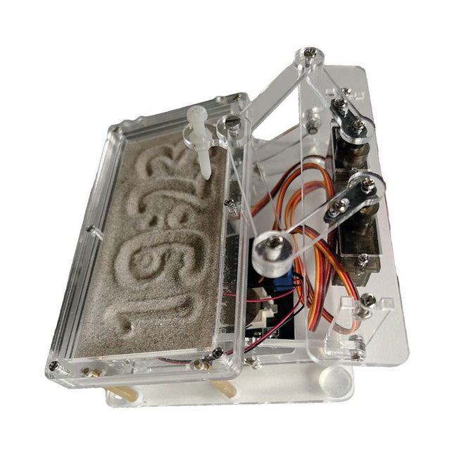
A standard sand clock just shows how time passes. In contrast, this Raspberry Pi Pico-controlled sand clock shows the exact time by “engraving” the four digits for hour and minute into the layer of sand. After an adjustable time the sand is flattened out by two vibration motors and everything begins all over again.
At the heart of the sand clock are two servo motors driving a writing pen through a pantograph mechanism. A third servo motor lifts the pen up and down. The sand container is equipped with two vibration motors to flatten the sand. The electronic part of the sand clock consists of a Raspberry Pi Pico and an RTC/driver board with a real-time clock, plus driver circuits for the servo motors.
A detailed construction manual is available for downloading.
Features
Dimensions: 135 x 110 x 80 mm
Build time: approx. 1.5 to 2 hours
Included
3x Precut acrylic sheets with all mechanical parts
3x Mini servo motors
2x Vibration motors
1x Raspberry Pi Pico
1x RTC/driver board with assembled parts
Nuts, bolts, spacers, and wires for the assembly
Fine-grained white sand
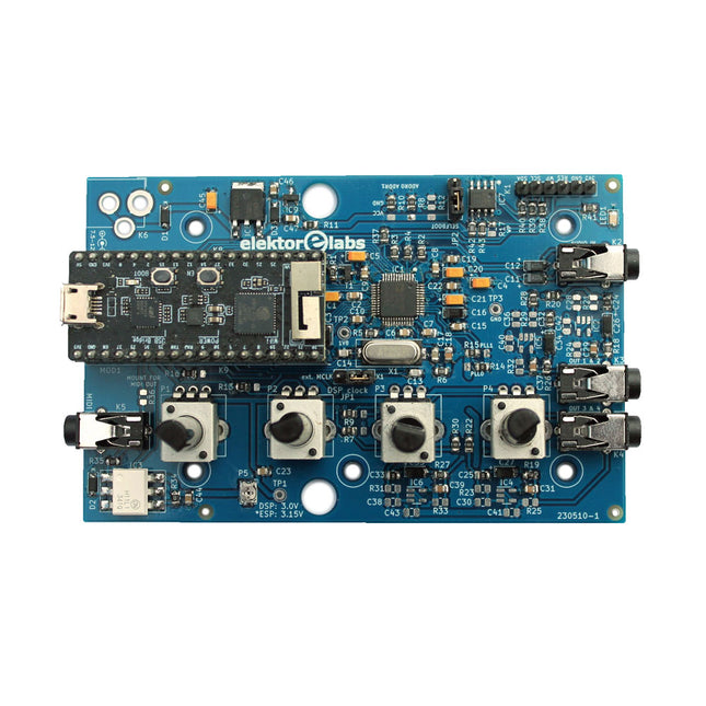
The Elektor Audio DSP FX Processor combines an ESP32 microcontroller and an ADAU1701 Audio DSP from Analog Devices. Besides a user-programmable DSP core, the ADAU1701 has high-quality analog-to-digital and digital-to-analog converters built-in and features an I²S port. This makes it suitable as a high-quality audio interface for the ESP32.
Programs for the ESP32 can be created with Arduino, Platform IO, CMake or by using the Espressif IDF in another way. Programs for the ADAU7101 audio DSPs are created with the free visual programming tool SigmaStudio by dragging and dropping pre-defined algorithm blocks on a canvas.
Applications
Bluetooth/Wi-Fi audio sink (e.g. loudspeaker) & source
Guitar effect pedal (stomp box)
Music synthesizer
Sound/function generator
Programmable cross-over filter for loudspeakers
Advanced audio effects processor (reverb, chorus, pitch shifting, etc.)
Internet-connected audio device
DSP experimentation platform
Wireless MIDI
MIDI to CV converter
and many more...
Specifications
ADAU1701 28-/56-bit, 50-MIPS digital audio processor supporting sampling rates of up to 192 kHz
ESP32 32-bit dual-core microcontroller with Wi-Fi 802.11b/g/n and Bluetooth 4.2 BR/EDR and BLE
2x 24-bit audio inputs (2 V RMS, 20 kΩ)
4x 24-bit audio outputs (0.9 V RMS, 600 Ω)
4x Control potentiometer
MIDI in- and output
I²C expansion port
Multi-mode operation
Power supply: 5 V DC USB or 7.5-12 V DC (barrel jack, center pin is GND)
Current consumption (average): 200 mA
Included
1x ESP32 Audio DSP FX Processor board (assembled)
1x ESP32-PICO-KIT
2x Jumpers
2x 18-pin headers (female)
4x 10 KB potentiometers
Downloads
Documentation
GitHub
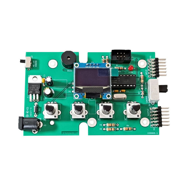
The Elektor Super Servo Tester can control servos and measure servo signals. It can test up to four servo channels at the same time.
The Super Servo Tester comes as a kit. All the parts required to assemble the Super Servo Tester are included in the kit. Assembling the kit requires basic soldering skills. The microcontroller is already programmed.
The Super Servo Tester features two operating modes: Control/Manual and Measure/Inputs.
In Control/Manual mode the Super Servo Tester generates control signals on its outputs for up to four servos or for the flight controller or ESC. The signals are controlled by the four potentiometers.
In Measure/Inputs the Super Servo Tester measures the servo signals connected to its inputs. These signals may come from for instance an ESC, a flight controller, or the receiver or another device. The signals are also routed to the outputs to control the servos or the flight controller or ESC. The results are shown on the display.
Specifications
Operating modes
Control/Manual & Measure/Inputs
Channels
3
Servo signal inputs
4
Servo signal outputs
4
Alarm
Buzzer & LED
Display
0.96' OLED (128 x 32 pixels)
Input voltage on K5
7-12 VDC
Input voltage on K1
5-7.5 VDC
Input current
30 mA (9 VDC on K5, nothing connected to K1 and K2)
Dimensions
113 x 66 x 25 mm
Weight
60 g
Included
Resistors (0.25 W)
R1, R3
1 kΩ, 5%
R2, R4, R5, R6, R7, R9, R10
10 kΩ, 5%
R8
22 Ω, 5%
P1, P2, P3, P4
10 kΩ, lin/B, vertical potentiometer
Capacitors
C1
100 µF 16 V
C2
10 µF 25 V
C3, C4, C7
100 nF
C5, C6
22 pF
Semiconductors
D1
1N5817
D2
LM385Z-2.5
D3
BZX79-C5V1
IC1
7805
IC2
ATmega328P-PU, programmed
LED1
LED, 3 mm, red
T1
2N7000
Miscellaneous
BUZ1
Piezo buzzer with oscillator
K1, K2
2-row, 12-way pinheader, 90°
K5
Barrel jack
K4
1-row, 4-way pin socket
K3
2-row, 6-way boxed pinheader
S1
Slide switch DPDT
S2
Slide switch SPDT
X1
Crystal, 16 MHz
28-way DIP socket for IC2
Elektor PCB
OLED display, 0.96', 128 x 32 pixels, 4-pin I²C interface
Links
Elektor Magazine
Elektor Labs
The FNIRSI HRM-10 is a portable, high-precision battery internal resistance and voltage tester. This device offers true four-wire measurement and is designed for both accuracy and ease of use. It automatically measures internal resistance and voltage values simultaneously, displaying the results on its HD color screen. Users have the option to manually adjust voltage and resistance ranges to suit their needs. The device also includes a sorting mode that automatically filters the good and bad batteries based on user-set thresholds. Additionally, it supports the storage of historical data and allows for exporting measurement records in table format.
Features
High Measurement Accuracy
Tabular Data Export
Auto-Evaluate Measurement Results
8 Threshold Settings
HD Color Screen
Folding Stand
1000 mAh Lithium Battery
Specifications
Voltage
Resistance
Measuring range
0-100 V (DC)
0-200 Ω
Accuracy
±0.5%
±0.5%
Gear
Automatic, 1 V, 10 V, 100 V
Automatic, 20 mΩ, 200 mΩ, 2 Ω, 20 Ω, 200 Ω
Instrument test signal frequency
1 Khz (AC)
Rechargeable
USB-C (5 V/1 A)
Built-in battery
1000 mAh lithium battery
User calibration
Yes
Sorting mode
Yes
History record
Yes
Recorded data export
Yes
Working environment
–10°C to +45°C, relative humidity <80%
Storage environment
–20°C to +80°C, relative humidity <80%
Dimensions
158.7 x 80.5 x 28.4 mm
Weight
225 g
Included
1x FNIRSI HRM-10 Internal Resistance Tester
1x Clip Test Line
1x USB-C data cable
1x Manual
Downloads
Manual
Firmware V0.3
Build Your Own Vintage Radio Broadcaster
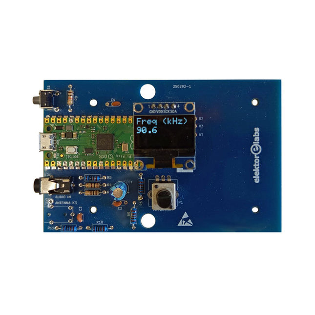
The Elektor AM Transmitter Kit allows streaming audio to vintage AM radio receivers. Based on a Raspberry Pi Pico microcontroller module, the AM Transmitter can transmit on 32 frequencies in the AM band, from 500 kHz up to 1.6 MHz in 32 steps of approx. 35 kHz.
The frequency is selected with a potentiometer and shown on a 0.96" OLED display. A pushbutton allows toggles the transmitting mode between On and Off. The range of the transmitter depends on the antenna. The onboard antenna provides a range of a few centimeters, requiring the AM Transmitter to be placed close to or inside the radio. An external loop antenna (not included) can be connected to increase the range.
The Elektor AM Transmitter Kit comes as a kit of parts that you must solder to the board yourself.
Features
The board is compatible with a Hammond 1593N enclosure (not included).A 5 VDC power supply with micro-USB connector (e.g., an old phone charger) is needed to power the kit (not included). Current consumption is 100 mA.
The Arduino software (requiring Earle Philhower’s RP2040 Boards Package) for the Elektor AM Transmitter Kit plus more information is available at the Elektor Labs page of this project.
Component List
Resistors
R1, R4 = 100 Ω
R2, R3, R8 = 10 kΩ
R5, R6, R9, R10, R11 = 1 kΩ
R7 = optional (not included)
P1 = potentiometer 100 kΩ, linear
Capacitors
C1 = 22 µF 16V
C2, C4 = 10 nF
C3 = 150 pF
Miscellaneous
K1 = 4×1 pin socket
K2, K3 = 3.5 mm socket
Raspberry Pi Pico
pushbutton, angle mount
0.96" monochrome I²C OLED display
PCB 150292-1