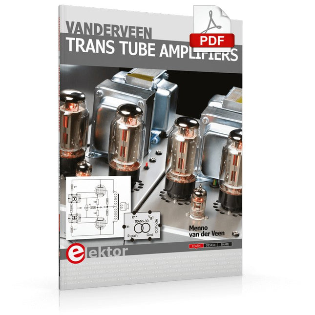
Ook in deze tijd klinken buizenversterkers nog steeds fantastisch, misschien wel mooier dan ooit. Nu hebben we immers de beschikking over moderne materialen als ringkern uitgangstransformatoren, uiterst hoogwaardige weerstanden en condensatoren en vele soorten goed klinkend draad. Ook de moderne geluidsbronnen als de CD speler en de nieuwste hoogwaardige luidsprekers laten beter dan ooit horen hoe goed de buizenversterker weergeeft.
Dit boek van Menno van der Veen kijkt niet alleen theoretisch naar buizenversterkers, maar vooral ook naar de ontwerpfase waarin besluiten moeten worden genomen over de doelen en eisen van de versterker. Hoe hangen deze samen met subjectieve en objectieve criteria? Welke schakelingen klinken vooral prachtig en waarom doen ze dat? Stel dat je een versterker gaat ontwikkelen en in de handel wilt brengen, tegen welke problemen loop je dan aan? En wat te zeggen van het belang en de betekenis van metingen? Zeggen ze nu iets of zeggen ze niets? Dankzij de grote rekenkracht van de computer kunnen we tegenwoordig dieper meten dan ooit. Hoe pas je deze technieken toe bij buizenversterkers? Tot nu toe waren metingen over frequentiebereik en vermogen en vervorming voldoende om een beeld van de eigenschappen van een versterker te geven. Maar zijn zulke metingen voldoende of moeten we gaan meten zoals ons oor waarneemt, met echte muzieksignalen in plaats van meettoontjes? De auteur schetst een toekomst waarbij meten aan de versterker de eigenschappen van ons horen moet volgen om tot nieuwe inzichten te komen.
Dit boek is meer op de praktijk gericht dan op de theorie en heeft een beschouwend karakter, alsof de auteur van bovenaf naar de buizenversterker kijkt. Kenniselementen worden geïntegreerd en in een breed overzichtelijk kader geplaatst.
This book focuses more on practical aspects than on theory, and it has an contemplative nature, as though the author were viewing amplifiers from above. Knowledge elements are integrated and placed in the context of a broad overview.
Even now tube amplifiers still sound great perhaps better than ever before. In part that is because we now have access to modern components such as toroidal output transformers, extremely high-quality resistors and capacitors, and many sorts of wire with good acoustic properties. Modern audio sources, such as CD players, and the latest top-end loudspeakers also enable us to appreciate how well tube amplifiers reproduce music even better than before.
This new book from Menno van der Veen looks at tube amplifiers from more than just a theoretical perspective. It focuses primarily on the design phase, where decisions must be taken with regard to the purpose and requirements of the amplifier, and it addresses the following questions: How do these aspects relate to subjective and objective criteria? Which circuits sound the best, and why? If you want to develop and market an amplifier, what problems should you expect? What are the significance and meaning of measurements? Are they still meaningful, or have they lost their relevance?
Thanks to the enormous processing power of computers, we can now measure more details than ever before. How can these new methods be applied to tube amplifiers? Previously it was sufficient to measure the frequency range, power and distortion of an amplifier in order to characterize the amplifier. Are these measurements still sufficient, or should we start measuring according to how we hear, using real music signals instead of waveforms from signal generators? The author sketches a future where amplifier measurements that conform to our sense of hearing enable us to arrive at new insights.
This book focuses more on practical aspects than on theory, and it has an contemplative nature, as though the author were viewing amplifiers from above. Knowledge elements are integrated and placed in the context of a broad overview.
Menno van der Veen is well known for his research publications on tube amplifiers used in audio systems.
In this book he describes one of his research projects which focuses on the question of whether full compensation for distortion in tubes and output transformers is possible.
In the past, a variety of techniques have been developed. One of them has largely been forgotten: trans-conductance, which means converting current into voltage or voltage into current. Menno van der Veen has breathed new life into this technique with his research project titled “Trans”. This book discusses all aspects of this method and discusses its pitfalls. These pitfalls are addressed one by one. The end result is a set of stringent requirements for Trans amplifiers.
Armed with these requirements, Menno then develops new Trans amplifiers, starting with Transie 1 and Transie 2. These DC-coupled, single-ended tube amplifiers have unusually good characteristics and are suitable for hobbyist construction. Next the Trans principle is applied to amplifiers with higher output power.
A trial-and-error process ultimately leads to the Vanderveen Trans 30 amplifier, which optimizes the features of Trans. The characteristics of this amplifier are so special and unique that Menno believes he has struck gold. To ensure that variations in tube characteristics cannot interfere with optimal Trans behavior, Menno makes use of simulations and comparison with other amplifier types. This book reads like an adventure story, but it is much more – it is an account of solid research into new ways to achieve optimal audio reproduction.
Niemand twijfelt er aan dat buizenversterkers een opmerkelijk mooi geluid produceren. Ze klinken levendig, diep en doortekend; het klankbeeld is zeer aangenaam en dynamisch schijnen ze nagenoeg geen beperkingen te kennen.Via een systematisch theoretisch onderzoek gaat de auteur na waardoor deze fraaie eigenschappen ontstaan. Hij ontwikkelt nieuwe modellen voor versterkerbuizen en transformatoren, waardoor het mogelijk wordt om op voorhand, tijdens het ontwerp, al te bepalen wat de eigenschappen van de buizenversterker worden. De koppeling tussen eindbuizen en de uitgangstransformator wordt diepgaand gemodelleerd. Daarbij ontstaan nieuwe inzichten in een uitzonderlijk soort vervorming: de dynamische dempingsfactor vervorming (DDFD).
Via rekenmodellen in het complexe domein worden vooral de eigenschappen in de grenzen van het hoorbare gebied (tussen 20 Hz en 20 kHz) onderzocht en ontstaan stabiliteitsvoorwaarden waar de versterker minstens aan moet voldoen. In versterkers wordt vaak tegenkoppeling toegepast, die uitgebreid wordt gemodelleerd en waarvan de gehoorsmatige gevolgen diepgaand worden besproken.Vervolgens wordt een fraaie selectie van bijzondere buizenversterkers besproken.
Kenmerkend in dit boek is dat de auteur niet alleen technisch schrijft, maar verhalend laat zien dat het ontwikkelen van buizenversterkers ook ingrijpt in je dagelijkse leven; zelfs het nut van patenten wordt besproken. Samenvattend: nieuwe theorieën en oplossingen voor een perfecte audiokwaliteit met buizenversterkers. Zowel de zelfbouwer als diegene die kennis en inzicht wil verwerven zal dit boek met plezier ter hand nemen.
Met ringkern-uitgangstranformatoren
Buizenversterkers vormen voor velen het neusje van de zalm, wanneer het gaat om de versterking van audiosignalen. De combinatie van klassieke techniek met moderne componenten heeft geleid tot een ware revival van de buizenversterker. De toepassing van de in de afgelopen 15 jaar door de auteur ontwikkelde 'ringkern-uitgangstransformatoren' heeft daar mede toe bijgedragen. Opvallend aan deze transformatoren zijn vooral het extreem grote frequentie bereik en de geringe lineaire en niet-lineaire vervormingen.
Het hoe en waarom van de transformator wordt op verschillende niveaus uitgelegd, beginnend bij inleidende begripsvorming en eindigende bij complete wiskundige beschrijvingen, waarbij ook de samenwerking van de transformator met de buizen en de luidspreker centraal staat. Naast de beschrijving van schematuur en zelfbouw van eenvoudig na te bouwen moderne high-end buizenversterkers met een uitgangsvermogen van 10 tot 100 Watt, worden bijzondere buizenversterkers met ringkerntransformatoren besproken: innovatieve oplossingen voor perfecte audiokwaliteit.
Zowel de zelfbouwer als degene die kennis en inzicht wil verwerven in de complexe materie van transformatoren, buizenversterkers en audiosignaalverwerking zal dit boek met plezier ter hand nemen.
Ist es möglich, Fehler in Röhren und Ausgangstrafos spürbar zu kompensieren? Im vorigen Jahrhundert wurden sehr viele Maßnahmen zum Erreichen dieses Ziels entwickelt. Eine dieser Methoden ist in Vergessenheit geraten: Transkonduktanz, was soviel bedeutet wie „Umsetzung von Strom in Spannung” und umgekehrt. Autor Menno van der Veen hat diese Methode wieder zum Leben erweckt und gab ihr den Arbeitstitel „Trans”. Die Hintergründe und Eigenschaften werden genau so sorgfältig beschrieben wie die Fallstricke dieses Verfahrens, die Schritt für Schritt eliminiert werden. Dies führt letztlich zu einer Liste strenger Bedingungen, die von Trans erfüllt werden müssen.
Mit diesen Geräten entwickelt er neue Trans-Verstärker, die mit Trans-Mini-1 und Trans-Mini-2 beginnen. Dabei handelt es sich um einfach nachzubauende, DC-gekoppelte Single-Ended-Röhrenverstärker mit ungeahnt guten Eigenschaften. Anschließend wird Trans an Verstärker mit höherer Leistung angepasst. Durch abwechselnde Rückschläge und Erfolge schließlich entsteht der Vanderveen-Trans-30, in welchem das Gute des Trans noch weiter verbessert wurde. Die besonderen Eigenschaften dieses Verstärkers waren es, die Menno van der Veen schließlich zu der Aussage bewogen, „Gold” in seinen Händen zu halten.
Mittels Simulation und Vergleich mit anderen Verstärkertypen werden die Trans-Bedingungen erneut überprüft, um sicher zu stellen, dass Abweichungen in den Röhren das optimale Verhalten von Trans nicht beeinflussen.
Dieses Buch liest sich wie ein spannender Roman, aber es ist mehr: Eine solide Untersuchung hinsichtlich neuer Methoden zum Erreichen einer optimalen Audiowiedergabe.
VOYAGE DANS LES RÉSEAUX NEURONAUX (1ÈRE PARTIE)Les neurones artificiels
TEST DE PRÉCONFORMITÉ CEM POUR UN PROJET ALIMENTÉ EN COURANT CONTINUPartie 1 : RSIL double continu
CHARGE ÉLECTRONIQUE EN CC ET CAJusqu?à 400 V et 10 A (crête)
DÉMARRER EN ÉLECTRONIQUE (9)N'ayez pas peur du choc... un peu de « self control » suffit !
TRAITEMENT D'IMAGES AVEC LE MODULE JETSON NANO DE NVIDIA (1ÈRE PARTIE)Matériel et logiciel
ZOOM SUR LES TRANSFORMATEURS SECTEURComportement transitoire à l?allumage et l?extinction
« YES WE CAN » AVEC PICAN 3Module de bus CAN pour le Raspberry Pi 4
CENTRALE SOLAIRE SUR BALCONUn investissement vite amorti
PRISE DE VUE ET DIFFUSION VIDÉO EN CONTINU AVEC UN RASPBERRY PI 4La caméra Raspberry Pi HQ en action
UTILISATION D?ÉCRANS DANS LES PROJETS RASPBERRY PIExtrait : écrans à diodes électroluminescentes organiques (OLED)
PROPELLER 2 DE PARALLAX (4)Envoi de chaînes de caractères
60 ANS D?ELEKTORRegard sur septembre
DANS L?ANTRE DE?Menno van der Veen et de ses tubes amplificateurs
CIRCUITS HYBRIDES
ROSE DES VENTS AVEC LE CAPTEUR GY-271Ou pourquoi il faut faire des huit pour calibrer un capteur
MESUREZ VOTRE EMPREINTEÉlectronique et émissions de gaz à effet de serre
THERMOSTAT CONNECTÉ À ESP32Conservez votre vin à la bonne température !
LÉVITATION MAGNÉTIQUE, VERSION NUMÉRIQUEComparateur analogique remplacé par un ESP32 Pico
ULTIMATE ARDUINO UNO HARDWARE MANUAL - FR TRANSLATIONExtrait : chargeur d?amorçage du microcontrôleur principal
MICROPYTHON POUR L'ESP32 ET SES COPAINSPartie 2 : piloter facilement les écrans matriciels
CARTE MADMACHINE SWIFTIOUn langage récent pour du matériel tout nouveau
SUR LE VIFPassions incertaines
HEXADOKUCasse-tête pour elektorniciens
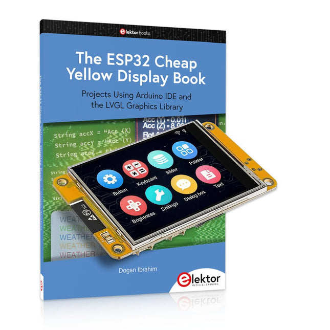
Over 40 Fully Tested ESP32 Projects Using Arduino IDE and the LVGL Graphics Library
This bundle includes the ESP32 Cheap Yellow Display (CYD) – a compact development board combining a standard ESP32 microcontroller with a 320x240 pixel TFT color display. The board also features multiple connectors for GPIO, serial communication (TX/RX), power, and ground. The built-in display is a major advantage, allowing users to create complex, graphics-based projects without the need for external LCDs or displays.
The accompanying book introduces the CYD board's hardware and on-board connectors in detail. It provides a range of beginner to intermediate-level projects developed using the popular Arduino IDE 2.0. Both basic graphics functions and the powerful LVGL graphics library are covered, with practical projects illustrating each approach.
All included projects have been fully tested and are ready to use. The book provides block diagrams, circuit schematics, complete code listings, and step-by-step explanations. With the LVGL library, readers can create modern, full-color graphical interfaces using widgets such as buttons, labels, sliders, calendars, keyboards, charts, tables, menus, animations, and more.
ESP32 Cheap Yellow Display Board
This development board (also known as "Cheap Yellow Display") is powered by the ESP-WROOM-32, a dual-core MCU with integrated Wi-Fi and Bluetooth capabilities. It operates at a main frequency of up to 240 MHz, with 520 KB SRAM, 448 KBROM, and a 4 MB Flash memory. The board features a 2.8-inch display with a resolution of 240x320 and resistive touch.
Furthermore, the board includes a backlight control circuit, touch control circuit, speaker drive circuit, photosensitive circuit, and RGB-LED control circuit. It also provides a TF card slot, serial interface, DHT11 temperature and humidity sensor interface, and additional IO ports.
The module supports development in Arduino IDE, ESP-IDE, MicroPython, and Mixly.
Applications
Image transmission for Smart Home device
Wireless monitoring
Smart agriculture
QR wireless recognition
Wireless positioning system signal
And other IoT applications
Specifications
Microcontroller
ESP-WROOM-32 (Dual-core MCU with integrated Wi-Fi and Bluetooth)
Frequency
Up to 240 MHz (computing power is up to 600 DMIPS)
SRAM
520 KB
ROM
448 KB
Flash
4 MB
Operating voltage
5 V
Power consumption
approx. 115 mA
Display
2.8-inch color TFT screen (240 x 320)
Touch
Resistive Touch
Driver chip
ILI9341
Dimensions
50 x 86 mm
Weight
50 g
Downloads
GitHub
This bundle contains:
The ESP32 Cheap Yellow Display Book (normal price: €35)
ESP32 Cheap Yellow Display Board (normal price: €25)
1x ESP32 Dev Board with 2.8" Display and acrylic Shell
1x Touch pen
1x Connector cable
1x USB cable
This upgraded version 2.0 (available exclusively from Elektor) contains the following improvements:
Enhanced protective earthing (PE) for furnace chassis
Extra thermal insulation layer around furnace to reduce odors
Connection to a computer, allowing curve editing on a PC
Features such as constant temperature control and timing functions
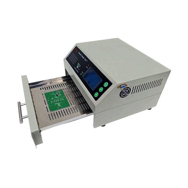
The infrared IC heater T-962 v2.0 is a microprocessor-controlled reflow oven that you can use for effectively soldering various SMD and BGA components. The whole soldering process can be completed automatically and it is very easy to use. This machine uses a powerful infrared emission and circulation of the hot air flow, so the temperature is being kept very accurate and evenly distributed.
A windowed drawer is designed to hold the work-piece, and allows safe soldering techniques and the manipulation of SMDBGA and other small electronic parts mounted on a PCB assembly. The T-962 v2.0 may be used to automatically rework solder to correct bad solder joints, remove/replace bad components and complete small engineering models or prototypes.
Features
Large infrared soldering area
Effective soldering area: 180 x 235 mm; this increases the usage range of this machine drastically and makes it an economical investment.
Choice of different soldering cycles
Parameters of eight soldering cycles are pre defined and the entire soldering process can completed automatically from Preheat, Soak and Reflow through to cool down.
Special heat up and temperature equalization with all designs
Uses up to 800 Watts of energy efficient Infrared heating and air circulation to re-flow solder.
Ergonomic design, practical and easily operated
Good build quality but at the same time light weight and a small footprint allows the T-962 v2.0 to be easily bench positioned transported or stored.
Large number of available functions
The T-962 v2.0 can solder most small parts of PCB boards, for example CHIP, SOP, PLCC, QFP, BGA etc. It is the ideal rework solution from single runs to on-demand small batch production.
Specifications
Soldering area (max)
180 x 235 mm (7.1 x 9.3")
Power (max)
800 W
Temperature range
0-280°C (32-536°F)
Heating method
Infrared
Processing time
1~8 minutes
Power supply
220 V AC/50 Hz
Display
LCD with Backlight
Control mode
8 intelligent temperature curves
Dimensions
310 x 290 x 170 mm (12.2 x 11.4 x 6.7")
Weight
6.2 kg
Included
1x T-962 v2.0 Reflow Soldering Oven (Elektor Version)
2x Fuses
1x Power cord (EU)
Mit dem Elektor Arduino Nano Trainingsboard (MCCAB) eigene Projekte realisieren
Der Mikrocontroller ist das wohl faszinierendste Teilgebiet der Elektronik, denn aufgrund der Vielzahl von Funktionen, die er auf seinem Chip vereinigt, ist er für den Entwickler ein universelles Multi-Tool zur Realisierung seiner Projekte. Praktisch jedes Gerät des täglichen Gebrauchs wird heute von einem Mikrocontroller gesteuert. Für einen elektronischen Laien blieb es aufgrund der Komplexität bisher allerdings ein Wunschtraum, eigene Ideen mit einem Mikrocontroller zu realisieren. Das Arduino-Konzept hat den Einsatz von Mikrocontrollern weitgehend vereinfacht, sodass jetzt auch Laien eigene Elektronik-Ideen mit einem Mikrocontroller verwirklichen können.
Buch & Hardware im Bundle: 'Learning by Doing'
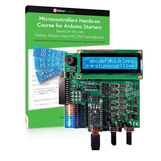
Dieses im Bundle mitgelieferte Buch (im großen A4-Format) zeigt, wie man auch ohne große Erfahrung in Elektronik und Programmiersprachen eigene Projekte mit einem Mikrocontroller realisieren kann. Es ist ein Mikrocontroller-Praxiskurs für Einsteiger, denn nach einem Überblick über die Interna des Mikrocontrollers und einer Einführung in die Programmiersprache C liegt der Schwerpunkt des Kurses auf den praktischen Übungen. Der Leser eignet sich die erforderlichen Kenntnisse durch 'Learning by Doing' an: in dem umfangreichen Praxisteil mit 12 Projekten und 46 Übungen wird das im vorderen Teil des Buches Gelernte mit vielen Beispielen unterlegt. Die Übungen sind dabei so aufgebaut, dass der Bearbeiter eine Aufgabenstellung erhält, die er mit seinem im Theorieteil des Buches aufgebauten Wissen löst. Für jede Übung gibt es anschließend eine ausführlich erklärte und kommentierte Musterlösung, die dem Bearbeiter bei Problemen weiterhilft und die er mit seiner eigenen Lösung vergleichen kann.
Arduino IDE
In der Arduino IDE, einer Software-Entwicklungsumgebung, die kostenlos auf den eigenen PC heruntergeladen werden kann und die das gesamte Softwarepaket enthält, das für ein eigenes Mikrocontroller-Projekt benötigt wird, schreibt der Bearbeiter mit dem Editor der IDE seine Programme („Apps“) in der Programmiersprache C. Der in die Arduino IDE integrierte Compiler übersetzt sie in die Bits und Bytes, die der Mikrocontroller versteht und die dann über ein USB-Kabel in den Speicher des Mikrocontrollers auf dem Elektor Arduino Nano Trainingsboard (MCCAB) geladen werden.
Externe Sensoren, Motoren oder Baugruppen abfragen oder steuern
Das Elektor Arduino Nano Trainingsboard (MCCAB) enthält neben einem Mikrocontrollermodul Arduino Nano alle für die Übungen benötigten Bauteile wie Leuchtdioden, Schalter, Taster, akustische Signalgeber usw. Auch externe Sensoren, Motoren oder Baugruppen können mit diesem Mikrocontroller-Übungssystem abgefragt oder gesteuert werden.
Technische Daten (Arduino Nano Trainingsboard MCCAB)
Stromversorgung
Über die USB-Verbindung des zur Erstellung der Programme sowieso angeschlossenen PCs oder ein externes Netzteil (nicht im Lieferumfang enthalten)
Betriebsspannung
+5 Vcc
Eingangsspannung
Alle Eingänge
0 V bis +5 V
VX1 und VX2
+8 V bis +12 V (nur bei Verwendung eines externen Netzteils)
Mikrocontrollermodul
Arduino Nano
Hardwareperipherie
LCD
2x16 Zeichen
Potenziometer P1 & P2
JP3: Auswahl der Betriebsspannung von P1 & P2
Verteiler
SV4: Verteiler für die BetriebsspannungenSV5, SV6: Verteiler für die Ein-/Ausgänge des Mikrocontrollers
Schalter und Taster
RESET-Taster auf dem Arduino Nano-Modul6x Tastschalter K1 … K66x Schiebeschalter S1 … S6JP2: Verbindung der Schalter mit den Eingängen des Mikrocontrollers
Summer
Piezo-Summer Buzzer1 mit Steckbrücke auf JP6
Leuchtanzeigen
LED L auf dem Arduino Nano-Modul, verbunden mit GPIO D1311x LED: Zustandsanzeige für die Ein-/AusgängeJP6: Verbindung der LEDs LD10 … LD20 mit den GPIOs D2 … D12
Serielle SchnittstellenSPI & I²C
JP4: Auswahl des Signals an Pin X der SPI-Steckerleiste SV12SV9 bis SV12: SPI-Interface (3,3 V/5 V) bzw. I²C-Interface
Schaltausgang für externe Geräte
SV1, SV7: Schaltausgang (maximal +24 V/160 mA, extern zugeführt)SV2: 2x13 Pins zum Anschluss externer Module
3x3 LED-Matrix (9 rote LEDs)
SV3: Spalten der 3x3 LED-Matrix (Ausgänge D6 … D8)JP1: Verbindung der Reihen mit den GPIOs D3 … D5
Software
Library MCCABLib
Steuerung der Hardware-Komponenten (Schalter, Taster, Leuchtdioden, 3x3 LED-Matrix, Summer) auf dem MCCAB Trainingsboard
Betriebstemperatur
bis +40 °C
Abmessungen
100 x 100 x 20 mm
Technische Daten (Arduino Nano)
Mikrocontroller
ATmega328P
Architektur
AVR
Betriebsspannung
5 V
Flashspeicher
32 KB, davon 2 KB vom Bootloader belegt
SRAM
2 KB
Taktfrequenz
16 MHz
Analoge IN-Pins
8
EEPROM
1 KB
DC-Strom pro I/O-Pin
40 mA an einem I/O-Pin, insgesamt maximal 200 mA an allen Pins gemeinsam
Eingangsspannung
7-12 V
Digitale I/O-Pins
22 (6 davon sind PWM-fähig)
PWM-Ausgänge
6
Stromverbrauch
19 mA
Abmessungen
18 x 45 mm
Gewicht
7 g
Lieferumfang
Elektor Arduino Nano MCCAB Trainingsboard
Arduino Nano
Buch: Mikrocontroller-Praxiskurs für Arduino-Einsteiger
Realize your own projects with the Elektor Arduino Nano MCCAB Training Board
The microcontroller is probably the most fascinating subfield of electronics. Due to the multitude of functions, it combines on its chip, it is a universal multi-tool for developers to realize their projects. Practically every device of daily use today is controlled by a microcontroller. However, for an electronic layman, realizing his own ideas with a microcontroller has so far remained a pipe dream due to its complexity. The Arduino concept has largely simplified the use of microcontrollers, so that now even laymen can realize their own electronics ideas with a microcontroller.
Book & Hardware in the Bundle: 'Learning by Doing'
This book, which is included in the bundle, shows how you can realize your own projects with a microcontroller even without much experience in electronics and programming languages. It is a microcontrollers hands-on course for starters, because after an overview of the internals of the microcontroller and an introduction to the programming language C, the focus of the course is on the practical exercises. The reader acquires the necessary knowledge by 'learning by doing': in the extensive practical section with 12 projects and 46 exercises, what is learned in the front part of the book is underpinned with many examples. The exercises are structured in such a way that the user is given a task to solve using the knowledge built up in the theoretical part of the book. Each exercise is followed by a sample solution that is explained and commented on in detail, which helps the user to solve problems and compare it with his own solution.
Arduino IDE
The Arduino IDE is a software development environment that can be downloaded for free to your own PC and that contains the entire software package needed for your own microcontroller projects. You write your programs ('apps') with the IDE’s editor in the C programming language. You translate them into the bits and bytes that the microcontroller understands using the Arduino IDE's built-in compiler, and then load them into the microcontroller's memory on the Elektor Arduino MCCAB Nano Training Board via a USB cable.
Query or control external sensors, motors or assemblies
In addition to an Arduino Nano microcontroller module, the Elektor Arduino Nano MCCAB Training Board contains all the components required for the exercises, such as light-emitting diodes, switches, pushbuttons, acoustic signal transmitters, etc. External sensors, motors or assemblies can also be queried or controlled with this microcontroller training system.
Specifications (Arduino Nano MCCAB Training Board)
Power Supply
Via the USB connection of the connected PC or an external power supply unit (not included)
Operating Voltage
+5 Vcc
Input Voltage
All inputs
0 V to +5 V
VX1 and VX2
+8 V to +12 V (only when using an external power supply)
Hardware periphery
LCD
2x16 characters
Potentiometer P1 & P2
JP3: selection of operating voltage of P1 & P2
Distributor
SV4: Distributor for the operating voltagesSV5, SV6: Distributor for the inputs/outputs of the microcontroller
Switches and buttons
RESET button on the Arduino Nano module 6x pushbutton switches K1 ... K6 6x slide switches S1 ... S6 JP2: Connection of the switches with the inputs of the microcontroller
Buzzer
Piezo buzzer Buzzer1 with jumper on JP6
Indicator lights
11 x LED: Status indicator for the inputs/outputs LED L on the Arduino Nano module, connected to GPIO D13 JP6: Connection of LEDs LD10 ... LD20 with GPIOs D2 ... D12
Serial interfacesSPI & I²C
JP4: Selection of the signal at pin X of the SPI connector SV12 SV9 to SV12: SPI interface (3.3 V/5 V) or I²C interface
Switching output for external devices
SV1, SV7: Switching output (maximum +24 V/160 mA, externally supplied) SV2: 2x13 pins for connection of external modules
3x3 LED matrix(9 red LEDs)
SV3: Columns of the 3x3 LED matrix (outputs D6 ... D8) JP1: Connection of the rows with the GPIOs D3 ... D5
Software
Library MCCABLib
Control of hardware components (switches, buttons, LEDs, 3x3 LED matrix, buzzer) on the MCCAB Training Board
Operating Temperature
Up to +40 °C
Dimensions
100 x 100 x 20 mm
Specifications (Arduino Nano)
Microcontroller
ATmega328P
Architecture
AVR
Operating Voltage
5 V
Flash Memory
32 KB, of which 2 KB used by bootloader
SRAM
2 KB
Clock Speed
16 MHz
Analog IN Pins
8
EEPROM
1 KB
DC Current per I/O Pins
40 mA on one I/O pin, total maximum 200 mA on all pins together
Input Voltage
7-12 V
Digital I/O Pins
22 (6 of which are PWM)
PWM Output
6
Power Consumption
19 mA
Dimensions
18 x 45 mm
Weight
7 g
Included
Elektor Arduino Nano MCCAB Training Board
Arduino Nano
Book: Microcontrollers Hands-on Course for Arduino Starters
This bundle is all about designing projects based on the 555 timer IC. The book features over 45 fully tested and documented projects. Together with the kit, which contains more than 130 through-hole components, you can build all the projects described on a breadboard. The setup also makes it easy to modify and experiment with the projects.
Over 45 Builds for the Legendary 555 Chip (and the 556, 558)
Some of the projects in the book are:
Alternately Flashing Two LEDs
Changing LED Flashing Rate
Touch Sensor On/Off Switch
Switch On/Off Delay
Light-Dependent Sound
Dark/Light Switch
Tone Burst Generator
Long Duration Timer
Chasing LEDs
LED Roulette Game
Traffic Lights
Continuity Tester
Electronic Lock
Switch Contact Debouncing
Toy Electronic Organ
Multiple Sensor Alarm System
Metronome
Voltage Multipliers
Electronic Dice
7-Segment Display Counter
Motor Control
7-Segment Display Dice
Electronic Siren
Various Other Projects
Kit Contents
Resistors
1x 15 kΩ
1x 68 kΩ
2x 47 kΩ
1x 82 kΩ
2x 820 Ω
1x 8.2 kΩ
3x 10 kΩ
1x 1.8 kΩ
1x 6.8 kΩ
14x 2.2 kΩ
10x 680 Ω
1x 27 kΩ
1x 5.6 kΩ
1x 560 kΩ
1x 4.7 kΩ
1x 3.3 kΩ
3x 33 kΩ
1x 36 kΩ
2x 100 kΩ
5x 1 kΩ
1x 3.9 kΩ
2x 56 kΩ
2x 12 kΩ
1x 10 kΩ potentiometer
1x 1 MΩ potentiometer
2x 50 kΩ potentiometer
3x 20 kΩ potentiometer
1x 10 kΩ potentiometer
1x 10 kΩ potentiometer
1x 50 kΩ potentiometer
1x 100 kΩ potentiometer
1x 50 kΩ potentiometer
Capacitors
1x 0.33 μF
1x 1 μF
1x 10 nF
1x 22 nF
1x 47 nF
1x 100 nF
1x 10 μF electrolytic
1x 33 μF electrolytic
2x 100 μF electrolytic
LEDs
10x 5 mm red LED
10x 3 mm red LED
3x 3 mm yellow LED
3x 3 mm green LED
1x Common-cathode 7-segment LED
Semiconductors
3x 555 timer
1x CD4017 counter
1x CD4026 counter
1x CD4011 NAND gate
4x 1N4148 diode
1x IRFZ46N MOSFET
1x Thermistor
1x Light dependent resistor (LDR)
Miscellaneous
1x Passive buzzer
1x Active buzzer
1x SG90 servo
1x 8 Ω mini loudspeaker
1x 9 V DC brushed motor
1x 5 V relay
1x 9 V battery clip
7x Pushbutton switches
1x Breadboard
1x Breadboard jumper wires