
Search results for "lc or meter or kit"
-

FNIRSI FNIRSI LC1020E High Precision LCR Meter
The FNIRSI LC1020E High-Precision LCR Meter with ESR tester is a portable and intelligent solution for testing electronic components, offering a basic accuracy of up to 0.3%. It is ideal for engineers, technicians, and makers. The device supports L/Q, C/D, and R/D measurements using both series and parallel equivalent circuit models, and features a 2.8-inch TFT color display. With preset thresholds and audio-visual alerts, it enables fast pass/fail evaluation, making it perfect for batch testing and quality control. Supporting test frequencies up to 100 kHz, it is well suited for high-frequency analysis of inductors, capacitors, and resistors. Features ±0.05% accuracy with 4.5-digit resolution Automatic R/L/C identification for fast measurements 5 test frequencies (100 Hz–100 kHz) & 3 voltage levels (0.1–0.6 V) Dual display: L/C/R/Z + X/D/Q/θ/ESR Sorting mode & bias voltage for batch testing Dual ports (3-/5-terminal) with 4-wire Kelvin support Data hold & logging for efficient workflow Compact, rechargeable (3000 mAh) – ideal for lab & field use Specifications General Test Frequency 100 Hz, 120 Hz, 1 kHz, 10 kHz, 100 kHz Basic Accuracy 0.3% Display 2.8-inch TFT LCD display Display Digits Main Parameter: 4.5 digits Secondary Parameter: 4.5 digits Measurement Parameters Main Parameters: AUTO/R/C/L/Z Secondary Parameters: X/D/Q/θ/ESR Measurement Range L: 0-100H C: 0-100mF R: 0-10M Internal Bias 0.0 V, 0.5 V Test Level 0.1 V, 0.3 V, 0.6 V Calibration Functions Open circuit calibration, Short circuit calibration Comparison Function Used to calculate the relative error between the component measurement value and the nominal value, displayed as a percentage, and provides filtering results. Nominal values and tolerance can be set, with tolerance range adjustable from 0.1% to 99.9% Function Record Checks if the measured component data meets the set nominal value and tolerance, recording the number of successful and failed measurements Test Terminal Configuration Three-terminal, Five-terminal Output Impedance 100Ω Interface USB-C (Virtual serial port) Others Language settings, Screen brightness, Sound settings, Auto power-off, Calibration settings, System information Battery 3000 mAh Lithium battery Dimensions 18.5 x 8.5 x 3.5 cm Weight 680 g Capacitance (C) Range: 1mF-100mF 100 Hz: 5% ±5 digits 1 kHz: 3% ±5 digits 10 kHz: / 100 kHz: / Range: 1uF-1mF 100 Hz: 1% ±4 digits 1 kHz: 0.5% ±5 digits 10 kHz: 2% ±5 digits 100 kHz: 3% ±4 digits Range: 1nF-1uF 100 Hz: / 1 kHz: 0.3% ±2 digits 10 kHz: 0.4% ±2 digits 100 kHz: 1% ±4 digits Range: 1pF-1nF 100 Hz: / 1 kHz: 2% ±2 digits 10 kHz: 1.5% ±2 digits 100 kHz: 2% ±4 digits Inductance (L) Range: 1H-100H 100 Hz: 2% ±5 digits 1 kHz: 2% ±5 digits 10 kHz: / 100 kHz: / Range: 1mH-1H 100 Hz: 0.4% ±5 digits 1 kHz: 0.3% ±2 digits 10 kHz: 0.4% ±3 digits 100 kHz: 2.5% ±5 digits Range: 10uH-1mH 100 Hz: 3% ±5 digits 1 kHz: 0.5% ±4 digits 10 kHz: 0.5% ±3 digits 100 kHz: 1.5% ±5 digits Range: 1uH-10uH 100 Hz: / 1 kHz: 2% ±5 digits 10 kHz: 2% ±5 digits 100 kHz: 4% ±5 digits Resistance (R) Range: 1MΩ-10MΩ 100 Hz: 5% ±4 digits 1 kHz: 3% ±3 digits 10 kHz: / 100 kHz: / Range: 1KΩ-1MΩ 100 Hz: 0.4% ±4 digits 1 kHz: 0.2% ±2 digits 10 kHz: 0.3% ±3 digits 100 kHz: 0.6% ±5 digits Range: 1Ω-1KΩ 100 Hz: 1.5% ±4 digits 1 kHz: 0.3% ±2 digits 10 kHz: 0.3% ±3 digits 100 kHz: 0.6% ±5 digits Range: 10mΩ-1Ω 100 Hz: 4% ±4 digits 1 kHz: 2% ±5 digits 10 kHz: 2% ±5 digits 100 kHz: 5% ±5 digits Included 1x FNIRSI LC1020E LCR Meter 1x Kelvin Test Clip 2x Test Leads (1x black, 1x red) 1x Shorting Plate 1x USB-C Cable 1x Manual Downloads Manual Firmware V1.1
€ 69,95
Best Price
-
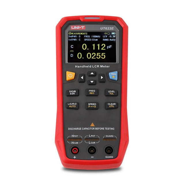
Uni-Trend UNI-T UT622E LCR Meter
The UT622E handheld LCR meter features powerful functions, high accuracy, fast speed, and long standby time. With a clear and intuitive 2.8-inch TFT LCD display, large-capacity rechargeable battery, and 100 kHz test frequency, the meter can be used for longstanding accurate and convenient measurement in any occasion. It is suitable for the measurement and screening of inductance, capacitance, and resistance in laboratories, production lines, maintenance points, etc. Features Max. test frequency: 100 kHz Accuracy: 0.1% Display count: 99999 Max. test rate: 20 times/s DCR: Yes Connectivity: Mini-USB Display: 2.8" TFT LCD Specifications Testfrequency 100 Hz, 120 Hz, 1 kHz, 10 kHz, 100 kHz Test level 0.1 Vmrs, 0.3 Vrms, 1 Vrms Output impedance 100 Ω Measurement parameters Primary: L/C/R/Z/DCRSecondary: D/Q/Θ/ESR DSR speed test Fast (20 times/s), medium (5 times/s), or slow (2 times/s) Range Auto/Hold Tolerance range 1%~20% Equivalent mode Series/Parallel Clearing connection Open/Short circuit Fuse of test ports 0.1 A/250 V Communication interface Mini-USB MAX reading of primary parameters 99999 MIN resolution 0.0001 Maximum accuracy 0.10% L 0.00 µH~99.999 H C 0.00 pF~99.999 mF Z/R 0.0000 Ω~9.9999 MΩ ESR 0.0000 Ω~999.99 Ω D 0.0000~9.9999 Q 0.0000~99999 Θ -179.9°~179.9° DCR 0.01 mΩ~20.000 MΩ Power supply 3.7 V/1800 mAh lithium polymer battery Display 2.8" TFT LCD (320x240) Dimensions 93 x 192 x 44 mm Weight 420 g Included UT622E LCR meter Short circuit board Four-terminal kelvin test leads USB cable Manual Downloads Datasheet Manual Software
€ 325,49
-
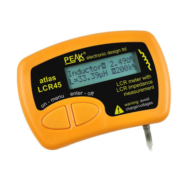
Peak Peak Atlas LCR45 LCR Meter
The Peak Atlas LCR45 does everything that the popular LCR40 does, but it has some significant enhancements. The LCR45 features a new high capacity micro and high resolution ADCs. LCR45 incorporates advanced maths, based on Complex Impedance analysis. This allows for enhanced component value measurement as well as a comprehensive and detailed impedance display. Features Supplied with gold plated removable hook probes Fluid measurements with hold function Automatic or manual component type Automatic or manual test frequency, DC, 1 kHz, 15 kHz or 200 kHz Enhanced measurement resolution: 0.2 µH, 0.2 pF and 0.2 Ohms Easy menu system for user settings Enhanced compensation for component parasitics and losses (such as core losses etc) Automatic or manual power-off Specifications Analyser type LCR and component impedance Component types Auto/Manual for L,C & R Measurement types Inductance, Capacitance and Resistance Other measurements Complex impedance/admittance More measurements Magnitude and Phase of impedance Inductance range 0uH to 2H Capacitance range 0 pF to 10000 uF Resistance range 0R to 2MR Test frequency Auto and manual: DC, 1 kHz, 15 kHz, 200 kHz Display type Alphanumeric LCD (not backlit) Measurement scheme Continuous (with optional hold) Battery GP23 (12 V/55 mAH type), ~700 ops Included LCR45 Passive Component Impedance Meter 2 mm plugs and sockets and removeable hook probes Comprehensive illustrated user guide 2 Batteries, one installed and one spare. GP23 Alkaline battery. (12 V/55 mAH) Downloads Datasheet (EN) User Guide (EN) User Guide (FR) User Guide (IT)
€ 131,89
-
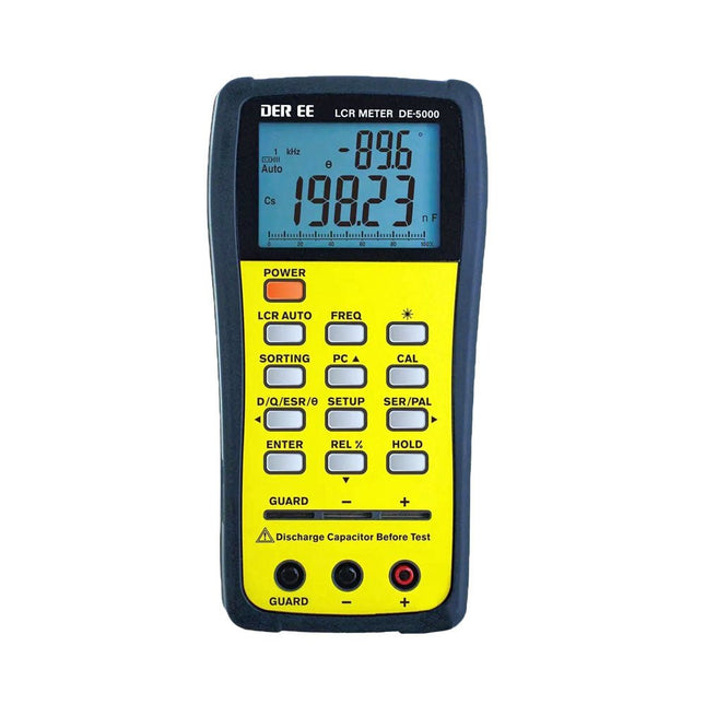
DER EE DER EE DE-5000 LCR Meter (100 kHz)
The DE-5000 is a smart, high-accurate, flexible and easy-to-use portable LCR meter. It features automatic LCR check, 4-wire Kelvin measurement, backlit display with 19999/1999 counts, multiple measurement modes and selectable test frequencies (100 Hz, 120 Hz, 1 kHz, 10 kHz or 100 kHz). The DE-5000 LCR meter is a practical helper for engineers or technicians. Features Auto L.C.R. check Ls/Lp/Cs/Cp/Rs/Rp/DCR with D/Q/θ/ESR measurement 4-wire Kelvin measurement 20,000 / 2,000 counts display Backlight Relative mode Series / Parallel modes Components sorting function Low battery indication Auto power off Specifications Test frequency 100 Hz / 120 Hz / 1 kHz / 10 kHz / 100 kHz Resistance range 20.000 Ω – 200.0 MΩ DCR range 200.00 Ω – 200.0 MΩ Capacitance range 200.00 pF – 20.00 mF Inductance range 20.000 µH – 2.000 KH Display (backlit LCD) 19999 / 1999 counts Selectable tolerance ±0.25%, ±0.5%, ±1%, ±2%, ±5%, ±10%, ±20% Power supply 9 V battery Dimensions 188 x 95 x 52 mm Weight 350 g (excluding battery) Included DE-5000 LCR meter Alligator test lead case (TL-21) AC/DC adaptor Guard line (TL-23) TL-22 SMD tweezers 9 V battery Carrying case Manual Downloads Datasheet
€ 192,39
-
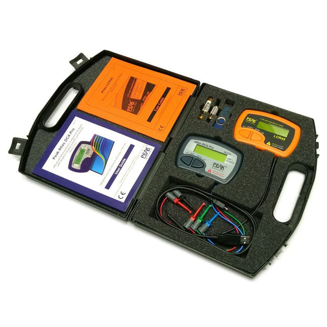
Peak Peak Atlas Pro Pack (LCR45 & DCA75)
This pack contains the LCR45 Passive Component Impedance Meter, great for advanced hobbyists and professionals. It also contains the very popular DCA Pro (model DCA75), fantastic for component identification, pinout identification, detailed characteristic measurement and curve tracing on a PC. Complete with USB cable and software on a USB flash drive. DCA75 Building on the continued success of Peak's existing component identification and analysis instruments, the DCA Pro brings an array of exciting new features for the hobbyist and professional alike. The DCA Pro is an advanced new design that features a graphics display, USB communications, PC Software and an enhanced component identification library. Automatic component type identification Automatic pinout identification (connect any way round) The DCA Pro supports all the components that the popular Peak Atlas DCA55 supports, but adds plenty more. Components supported include: Transistors (including Darlingtons), Silicon and Germanium types. Measures gain, Vbe and leakage MOSFETs, enhancement mode and depletion mode types. Measure on-threshold (at 5 mA) and approx transconductance (for span of 3-5 mA) JFETs, including normally off SiC types. Measures pinch-off voltage (at 1 uA) and approx transconductance (for span of 3-5 mA) IGBTs (insulated gate bipolar transistors). Measures on-threshold (at 5 mA) Diodes and Diode networks LEDs and bicolour LEDs (2 lead and 3 lead types) Zener Diodes with measurement of zener voltage up to 9 V at 5 mA Voltage regulators (measures regulation voltage, drop-out voltage, quiescent current) Triacs and Thyristors that require less than 10 mA of gate current and holding current Stand-alone or with a PC The instrument can be used stand-alone or connected to a PC. Either way, the DCA Pro will automatically identify the component type, identify the pinout and also measure a range of component parameters such as transistor gain, leakage, MOSFET and IGBT threshold voltages, pn characteristics and much more. Curve Tracing When connected to a PC using the supplied USB cable, a range of low current curve-tracing functions can be performed. Various graph types are available, with more to follow: Bipolar transistor output characteristics, IC vs VCE Bipolar transistor gain characteristics, HFE vs VCE Bipolar transistor gain characteristics, HFE vs IC MOSFET and IGBT output function, ID vs VDS MOSFET and IGBT transfer function, ID vs VGS JFET output function, ID vs VDS JFET transfer function, ID vs VGS Voltage regulator, VOUT vs VIN Voltage regulator, IQ vs VIN. PN junction I/V curves, forward and reverse options (for Zener diodes) Curve tracing is performed using test parameters in the range of +/-12 V or +/-12 mA. All curve-tracing data can be instantly pasted into Excel for further graphing and analysis. PC Software is included with the DCA Pro on a Peak USB memory stick. Software designed for Windows 7 and higher (all 32 or 64 bit). LCR45 A great handheld LCR analyzer that can measure the value of your passive component (inductor, capacitor or resistor) and also measure the detailed impedance in a number of modes. The LCR45 offers enhanced measurement resolution (better than 0.1 uH!) whilst also giving you continuous fluid measurements. Additionally, the test frequencies of DC, 1 kHz, 15 kHz and 200 kHz can be set to automatic or manual modes. Supplied with removable gold plated hook probes, battery and user guide. Compatible with standard 2 mm test connectors. Not designed for in-circuit use. Automatic or manual component type selection: Inductor, Capacitor or Resistor Automatic or manual test frequency selection: DC, 1 kHz, 15 kHz and 200 kHz Inductance from 0.1 uH to 10 H Capacitance from 0.1 pF to 10,000 uF Resistance from 0.1 Ohm to 2 MOhm Inductance measurement also shows DC winding resistance Display of "Component type and values", "Complex Impedance", "Magnitude/Phase" and "Admittance" Test frequency displayed for all measurements Typical accuracy of 1.5% for inductors and capacitors (see spec table for details) Typical accuracy of 1% for resistors Test lead complete with gold plated 2 mm plugs and sockets Supplied with removable gold plated hook probes Included LCR45 DCA75 Extra GP23 Battery Extra AAA cell Dual Carry Case
€ 325,49
-
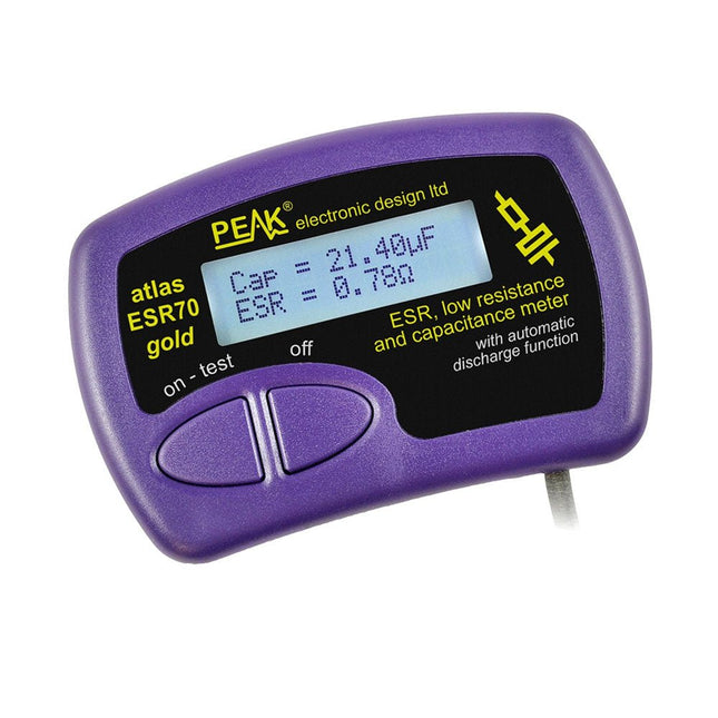
Peak Peak Atlas ESR70 gold (ESR and Capacitance Meter)
The Peak Atlas ESR70 gold is an enhanced version of the previous Peak Atlas ESR70 Plus. It does everything that the ESR70 Plus did but better. It now measures capacitance up to 10x faster, and over a wider range, thanks to new test algorithms. The capacitance measurement is also much less influenced by parallel resistances or leakage current thanks to our new Triple-Slope measurement system. Using the supplied gold plated probes (removable), the Atlas ESR70 gold can measure ESR down to a resolution of 0.01 ohms, up to 40 ohms. It can even measure ESR for capacitors that are in-circuit. Probes are removable, allowing 2 mm compatible probes to be fitted. Audible alerts are produced for various ESR levels allowing you to perform many tests in succession without having to look at the display. The ESR70 automatically takes capacitive reactance into account, so even low value capacitors (down to 0.3 uF) can have the ESR measured accurately. Features Uses a single AAA Alkaline cell (included) Alphanumeric LCD with backlight Automatic analysis-start when you apply the probes Automatic capacitor discharge using controlled discharge function ESR (and low DC resistance) measurement (even in-circuit) Capacitive reactance automatically taken into account to ensure accurate ESR Capacitance measurement (if testing out-of-circuit) Audible alerts for various ESR levels Extended ESR measurement range up to 40 Ohms Optional probe alternatives easily fitted New gold Features Improved LCD with better backlight 10x faster capacitance measurement for large capacitors Enhanced user options system New triple-slope measurement system to vastly reduce the influence of parallel resistance and/or leakage current on capacitance measurements Much wider capacitance measurement range now 0.3 uF to 90,000 uF (was 1uF to 22,000uF) Specifications Analyzer type ESR and Capacitance Component types Capacitors (>0.3 uF) ESR range 0.00 Ohms to 40.0 Ohms ESR resolution From 0.01 Ohms In-circuit use ESR only Capacitance range 0.3 uF to 90000 uF Battery type 1.5 V Alkaline AAA Cell (supplied). Life typically 1500 ops Display type Alphanumeric LCD (with backlight) Included Peak Atlas ESR70 gold Extra-long and extra-flexible test cables (450 mm of Silicone covered cable) 2 mm gold plated plugs and sockets with removeable gold plated crocodile clips Comprehensive illustrated user guide AAA Alkaline cell Downloads Datasheet (EN) User Guide (EN) User Guide (FR) User Guide (IT)
€ 143,99
-

Elektor Labs Elektor Low-Noise Lab Power Supply
The Elektor Low-Noise Lab Power Supply is a fully analogue, adjustable, medium-power symmetrical bench supply that contains no switching or digital components. It provides an output voltage adjustable between 0 V and ±22 V, and an output current adjustable from 0 A to 1 A. Because it avoids any form of switching circuitry, the design delivers extremely low noise. To display both output voltages and currents, four miniature moving-coil panel meters are used. Most modern laboratory power supplies and AC adapters employ switch-mode techniques. Even the best examples inevitably exhibit high-frequency ripple and other switching artefacts on their output, which can interfere with the testing of sensitive analogue circuits and disturb low-level measurements. To overcome this, the concept here is a completely analogue power supply. Although less efficient than its switch-mode counterparts, the reduced efficiency is of little importance for test-bench use and ensures cleaner, more reliable measurement results. Because many analogue circuits require a symmetrical supply, this design delivers positive and negative output voltages of equal magnitude. A small amount of adjustment is available to compensate for any imbalance. Naturally, a variable current-limit function is also included. The kit includes the components required to build the power supply, except for the transformers. Specifications Output Voltage 0…+22 V, 0, −22 V Output Current 0…+1 A, 0…−1 A Noise −85 dBV, (at 0.95 A/20 V, B = 22 kHz) −84 dBV (at 0.95 A/20 V, B > 500 kHz) Ripple 50 µVRMS (at 950 mA/20 V, B = 22 kHz, mainly 100 Hz component) Included 3x PCBs: Regulator (PCB-1), Mains Filter (PCB-2) and Transformer (PCB-3) All the components except the AC transformers 4x moving-coil meters Additional parts for wiring (wires, banana sockets, IEC Power entry module, etc.) Not included The three AC transformers An enclosure Parts List For the Regulator PCB (240386-1) Resistors (250 mW, 1%) R1 = 12 Ω R2, R8, R37, R62 = 1 MΩ R3, R7, R10, R13, R17, R20, R22, R30, R35, R42, R45, R47, R55, R60 = 100 Ω, 600 mW R4, R5 = 4.7 kΩ R6 = 100 kΩ R9, R12, R14, R36, R38, R39, R61, R63, R66, R72, R78, R79 = 10.0 kΩ, 600 mW R11 = 9.76 kΩ, 600 mW R15, R40 = 44.2 kΩ, 600 mW R16, R41, R77 = 1 kΩ R18, R43 = 1.5 kΩ, 1 W, 5% R19, R44 = 470 Ω, 1 W, 5% R21, R46 = 330 Ω, 600 mW R23, R24, R48, R49 = 1.0 Ω, 1 W R25, R50 = 1 kΩ, 1 W, 5% R26, R28, R51, R53 = 1.000 kΩ 0.1%, 15 ppm/C R27, R29, R52, R54 = 10.00 kΩ 0.1%, 15 ppm/C R31, R56 = 1.2 kΩ, 1 W, 5% R32, R57 = 47 kΩ R33, R58 = 270 Ω R34, R59 = 27 kΩ R64, R69 = 12.0 kΩ R65 = 3.0 kΩ, 600 mW R67, R80 = 470 Ω, 600 mW R68, R70 = 6.8 kΩ, 600 mW R71 = 30.0 kΩ,, 600 mW R73, R74, R75, R76 = 10 MΩ P1, P2, P3 = 10 kΩ, 200 mW, 20%, potentiometer, 1 turns, single, lin., panel mount P4, P5 = 500 Ω, 500 mW, 10%, trimmer, 25 turns, 3296Y-1-501LF Bourns P6, P7 = 10 kΩ, 500 mW, 10%, trimmer, 25 turns, 3296Y-1-501LF Bourns Capacitors C1 = 100 nF, 50 V, 10%, ceramic X7R, LS 5 mm C2, C3, C6, C7, C30 = 10 µF, 63V, 20%, LS 2.5 mm, 3000hours@105°C C4, C5, C8, C9, C13, C14, C18, C19, C23, C24, C28, C29, C31, C32, C38, C39 = 100 nF, 250 V, 10%, PET, LS 7.5 mm C10, C20 = 47 nF, 100 V, 5%, PET, LS 5 mm C11, C21 = 10 nF, 100 V, 5%, PET, LS 5 mm C12, C22 = 220 µF, 35 V, 20%, 0.024 Ω, LS2.5/3.5 mm, Ir 3.4 A, 2000hours@125°C, polymer C15, C25 = 120 µF, 50 V, 20%, ESR 0.02 Ω, Diam. 10 mm max., LS 5 mm C16, C26 = 15 nF, 100 V, 5%, PET, LS 5 mm C17, C27 = 47 nF, 100 V, 5%, PET, LS 5 mm C33, C34 = 22 µF, 50 V, 20%, LS 2 mm, 10000 hours @ 105°C C35, C36, C44, C45 = 1 µF, 100 V, 10%, LS 5 mm, ceramic X7R C37 = 100 uF, 50 V, 20%. LS 3.5 mm C40, C41, C42, C43, C46, C47, C48, C49 = 1000 µF, 50 V, 20%, LS 5/7.5 mm, Ir 3.32 A, 10000hours@105°C, D 16 mm C50, C51, C52, C53 = 47 nF, 100 V, 10%, ceramic X7R, LS 5 mm Inductors L1, L2 = 4.7 µH, 3.2 A, 0.033 Ω, LS 5 mm, RLB0914-4R7ML Bourns L3 = Commom mode choke, 14.5 mH, 3 A, SSRH24NH-30145 Kemet Semiconductors D1, D2, D3, D4, D5, D9, D10, D11, D15 = BAT85, DO-34 D6, D7, D12, D13 = SR560, DO-201AD D8, D14, D16 = 1N4148, DO-35 D17 = Zenerdiode, 5.6 V, 0.5 W, DO-41 D18, D19 = 1N4004, DO-41 D20, D21 D22, D23 = V30100CI-M3/P, dual common cathode, TO-220 D24 = Zener diode, 30 V, 1 W, DO-41 LED1, LED2 = LED, red, T-1 (3 mm) LED3, LED4 = LED, green, T-1 (3 mm) TVS1, TVS2 = BZW50-33B, R6 T1, T2, T4 = BC337.25, TO-92 T3 = NJW0302G, TO-3P T5, T6, T8 = BC327.25, TO-92 T7 = NJW0281G, TO-3P T9 = BD139, TO-126 (SOT-32) IC1 = LM334Z, TO-92 IC2 = LM4040AIZ-5.0/NOPB, TO-92 (TO-226AA-3) IC3, IC4 = OPA2992IDR, SOIC-8 IC5, IC6 = OPA4992IDR, SOIC-14 IC7 = OPA992IDBVR, SOT-23-5 IC8 = LM339N, DIP-14 IC9 = LM317, TO-220 IC10 = LM337, TO-220 Others F1, F2 = 5×20 mm fuse, 1.6 A, fast acting HS1, HS2 = Heatsink MC33271 (for T3/T7), 2.7°C/W, PCB mount, height 63.5 mm K1, K4 = 3-way screw terminal block, LS 3.5 mm, max. 1.5 mm² K2, K3 = 3-way screw terminal block, LS 3.5 mm, max. 1 mm² M1, M3 = Moving coil meter, Range 30 V, type 91C4, 45×45 mm M2, M4 = Moving coil meter, Range 1 A, type 91C4, 45×45 mm² RE1 = Relay DPDT,5V, UA2-5NU Miscellaneous 3× 3-way screw terminal block, LS 3.5 mm, max. 1 mm² (for P1, P2, P3) 4× Pin header, 1×2, vertical, pitch 2.54 mm (for LED1, LED2, LED3, LED4) 4× Pin socket, 1×2, vertical. pitch 2.54 mm (for LED1, LED2, LED3, LED4) 2× Heatsink FK222SA220, 20°C/W, PCB mount (for IC9 & IC10) 2× Mica thermal pad for TO-220, 12×18×0.05 mm (for IC9 & IC10) 2× Insulating bushing IB 6, TO-220 (for IC9 & IC10) 2× Ceramic thermal pad, 23×20×2 mm (for T3 & T7) 2× PCB Fuse Holder, for 5×20 mm fuse, 10 A (for F1, F2) 2× Cover for PCB Fuse Holder, transparent (for F1, F2) 2× 2-way screw terminal block, LS 3.5 mm, max. 1 mm² (for M1 & M3) 2× 2-way screw terminal block, LS 3.5 mm, max. 1.5 mm² (for M2 & M4) 8× M3 solder lug, thickness 0.35 mm (for M1…M4) M4 solder lug, thickness 0.35 mm (to connect 4 mm banana connectors) Screened cable, 1 pair, 2×24 AWG/0.22 mm², 1 m (for P1, P2 & P3) IC socket, DIP, 14 contacts (for IC8) M3 washer, plain, steel M3 screw, 16 mm, steel, pan head M3 nut M3 spring washer 50 mm M3 standoff, steel, male-female 12 mm M3 standoff, steel, male-female 10 mm M3 standoff, steel, male-female M3 screw, 8 mm, steel, pan head For the Mains Fiter PCB (240386-2) Resistor R1 = 220 kΩ, 1 W, 500 V, 5% Capacitors C1, C2 = 470 nF, 305 VAC, Class X2, 11 × 27 mm max., LS 15/22.5 mm C3, C4, C5, C6 = 2.2 nF, 300 VAC, Class Y2, 13 × 4 mm, LS 10 mm, PP Inductors L1, L2 = Common-mode choke, 6.8 mH, 1.7 A, TDK B82732R2172B030 Semiconductor MOV1 = TVS varistor, 300 VAC, S14K300 (230 VAC, B72214S0301K101) and SK14K150 (150 VAC, B72214S0151K101) Others K1, K2 = 3-way screw terminal block, LS 7.62 mm F1 = Time-delay fuse, 0.5 A (230 VAC) or 1 A (115 VAC) Miscellaneous 1× Fuse holder, 5×20 mm, 10 A, 500 VAC 1× Transparent fuse cover 4× 10 mm M3 standoff, steel, male–female 4× M3 screw, 8 mm, steel, pan head 4× M3 nut For the Transformer PCB (240386-3) Resistors R1, R2 = 2.7 kΩ, 600 mW, 1% R3 = 10.0 kΩ, 600 mW, 1% Capacitor C1 = 220 µF, 50 V, 20%, Ø10 mm, LS 5 mm, 4000 h @ 105°C Transformers (not included in this kit!) TR1, TR2, TR3 = 2×7 V, 25 VA, PCB-mounted toroid, 70060K Talema Semiconductors D1–D4 = 1N4148, DO-35 D5, D6 = 1N4004, DO-41 D7 = Zener 5.6 V, 1.3 W, DO-41 LED1 = LED, red, T-1 (3 mm) IC1, IC2 = MOC8021M, CTR ≥ 1000%, DIP-6 Others F1, F2, F3 = 160 mA time-delay fuse (230 VAC) or 315 mA time-delay fuse (115 VAC) K1 = 2-way screw terminal block, LS 7.62 mm K2 = 3-way screw terminal block, LS 3.5 mm, max 1.5 mm² K3, K4 = 3-way screw terminal block, LS 3.5 mm, max 1 mm² RE1, RE2 = Relay DPDT, 5 A/250 VAC / 24 VDC Miscellaneaous 1× Pin header 1×2, pitch 2.54 mm + matching socket for LED1 3× Fuse holder 5 × 20 mm, 10 A, 500 VAC + transparent cover 3× M4 screw, 8 mm, pan head + washer for TR1-TR3 8× M3 screw, 8 mm, pan head + nut + washer 8× 10 mm M3 standoff, steel, male–female 2× IC socket, DIP-6 for IC1 & IC2 Additional Parts 1 m red insulated wire, stranded, 1.5 mm² 0.5 m blue insulated wire, stranded, 1.5 mm² 0.5 m black insulated wire, stranded, 1.5 mm², 0.5 m 2 m red insulated wire, stranded, D 0.56 mm (0.25 mm²) 2 m black insulated wire, stranded, D 0.56 mm (0.25 mm²) 0.5 m Multicore Cable, Flexible, 3 Core, 0.75 mm² (24 x 0.2 mm) Red banana socket Black banana socket Blue banana socket Green banana socket IEC Power Entry Module with switch, IEC C14 3 crimp terminals, FASTON, 4.75 x 0.81 mm 3 knobs Links Elektor Labs JumpStarter Page Article (Part 1) Article (Part 2)
€ 249,00
Best Price
-

Elektor Bundles 555 Timer Projects (Bundle)
This bundle is all about designing projects based on the 555 timer IC. The book features over 45 fully tested and documented projects. Together with the kit, which contains more than 130 through-hole components, you can build all the projects described on a breadboard. The setup also makes it easy to modify and experiment with the projects. Over 45 Builds for the Legendary 555 Chip (and the 556, 558) Some of the projects in the book are: Alternately Flashing Two LEDs Changing LED Flashing Rate Touch Sensor On/Off Switch Switch On/Off Delay Light-Dependent Sound Dark/Light Switch Tone Burst Generator Long Duration Timer Chasing LEDs LED Roulette Game Traffic Lights Continuity Tester Electronic Lock Switch Contact Debouncing Toy Electronic Organ Multiple Sensor Alarm System Metronome Voltage Multipliers Electronic Dice 7-Segment Display Counter Motor Control 7-Segment Display Dice Electronic Siren Various Other Projects Kit Contents Resistors 1x 15 kΩ 1x 68 kΩ 2x 47 kΩ 1x 82 kΩ 2x 820 Ω 1x 8.2 kΩ 3x 10 kΩ 1x 1.8 kΩ 1x 6.8 kΩ 14x 2.2 kΩ 10x 680 Ω 1x 27 kΩ 1x 5.6 kΩ 1x 560 kΩ 1x 4.7 kΩ 1x 3.3 kΩ 3x 33 kΩ 1x 36 kΩ 2x 100 kΩ 5x 1 kΩ 1x 3.9 kΩ 2x 56 kΩ 2x 12 kΩ 1x 10 kΩ potentiometer 1x 1 MΩ potentiometer 2x 50 kΩ potentiometer 3x 20 kΩ potentiometer 1x 10 kΩ potentiometer 1x 10 kΩ potentiometer 1x 50 kΩ potentiometer 1x 100 kΩ potentiometer 1x 50 kΩ potentiometer Capacitors 1x 0.33 μF 1x 1 μF 1x 10 nF 1x 22 nF 1x 47 nF 1x 100 nF 1x 10 μF electrolytic 1x 33 μF electrolytic 2x 100 μF electrolytic LEDs 10x 5 mm red LED 10x 3 mm red LED 3x 3 mm yellow LED 3x 3 mm green LED 1x Common-cathode 7-segment LED Semiconductors 3x 555 timer 1x CD4017 counter 1x CD4026 counter 1x CD4011 NAND gate 4x 1N4148 diode 1x IRFZ46N MOSFET 1x Thermistor 1x Light dependent resistor (LDR) Miscellaneous 1x Passive buzzer 1x Active buzzer 1x SG90 servo 1x 8 Ω mini loudspeaker 1x 9 V DC brushed motor 1x 5 V relay 1x 9 V battery clip 7x Pushbutton switches 1x Breadboard 1x Breadboard jumper wires
€ 69,95€ 54,95Best Price
-
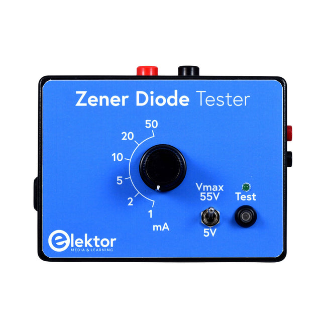
Elektor Zener Diode Tester
The Elektor Zener Diode Tester is essentially a constant-current source that can be switched in steps from 1 to 50 mA. It can be used to test Z-diodes up to a maximum of 54 V. Thanks to a 60-V step-up converter, the device can be powered by the usual 5 to 12 V. The principle of this tester is straightforward. A Z-diode or other DUT (device under test, such as an LED) is biased by an adjustable current source. The voltage across the DUT can be measured with a multimeter. The voltage of most (small) Z-diodes is specified at a current of 5 mA. Depending on the application, the voltage at other currents can also be of interest. That is why six current settings are available: 1, 2, 5, 10, 20, and 50 mA. LEDs are often specified at a current of 20 mA. What can be tested is: Whether a Z-diode is defective (short circuit or high impedance). Whether a Z-diode exhibits the correct Z-voltage. How a Z-voltage changes with different currents. What exact voltage is present at an integrated voltage reference. Whether LEDs in a series chain differ in brightness (hence the 20 mA current). What the current gain is for different base currents in (power) transistors. The kit contains all parts listed in the bill of materials including PCB and enclosure. Specifications Supply voltage 5…12 V/2 A (USB-C) Supply current (Itest = 50 mA) 1.1 A @ 5 V / 412 mA @ 12 V Selectable currents 1, 2, 5, 10, 20, and 50 mA Max. test voltage >54 V @ Itest ≥1 mA Max. output voltage 60 V @ Itest = 0 mA Voltage limit at 5 V 4.5 V @ Itest = 1 mA / 5.18 V @ Itest = 50 mA Enclosure dimensions 110 x 82 x 44 mm PCB size 105.4 x 67.3 mm Connections 4 mm banana sockets for multimeter 2 mm banana sockets for test clips USB-C socket for power supply Included Resistors R1 = 3.3 kΩ, 600 mW, 1% R2 = 0.15 Ω, 1 W, 5%, LS 12.7 mm, ø 3.5 mm R3, R8 = 180 Ω, 600 mW, 1% R4, R6, R16 = 1 kΩ, 600 mW, 1% R5, R19 = 47 kΩ, 600 mW, 1% R7 = 3.9 kΩ, 1 W, 5%, LS 12.7 mm, ø 3.5 mm R9, R10, R12 = 10 kΩ, 600 mW, 1% R11, R13 = 100 Ω, 600 mW 1% R14 = 249 Ω, 600 mW, 1% R15 = 499 Ω, 600 mW, 1% R17 = 2.49 kΩ, 250 mW, 1% R18 = 4.99 kΩ, 250 mW, 1% Capacitors C1 = 470 uF / 35 V, 20%, Ir = 1.86 A, ø 12.5 mm, LS 5 mm, ESR = 0.038 Ω (Panasonic EEUTP1V471) C2 = 1 uF / 100 V, 10%, X7R, LS 5 mm C3 = 2.2 nF / 50 V, 10%, X7R, LS 5 mm C4, C7 = 100 nF / 100 V, 10%, X7R, LS 5 mm C5 = 100 uF / 100 V, 20%, ø 14 mm max., LS 5 mm C6 = 1 nF / 100 V, 10%, X7R, LS 5 mm Inductor L1 = 100 uH, Irms = 2.4 A, Isat = 3.5 A, 0.09 Ω, radial, pitch 2.5/5/10 mm, ø 14 mm max. (Kemet SBC8-101-242) Semiconductors D1 = MUR120G, DO-41 D2, D4 = STPS3150RL, DO-201AD D3 = Z-diode, 18 V, 1.3 W (BZX85C18) D5 = Z-diode, 5.1 V, 0.5 W (1N5231B) LED1 = LED in pushbutton S1 LED2 = LED, green, 3 mm IC1 = MC34063, DIP-8 IC2 = LM4040BIZ-5.0/NOPB, TO-92 (TO-226AA-3) IC3 = TL051CP, DIP-8 T1 = BC327.25, TO-92 T2 = STP40NF10L, TO-220 T3 = IRF9510PBF, TO-220 T4 = 2N7000, TO-92 Others K1, K2, S1, S3 = 2-way screw terminal block, LS 3.5 mm, max. 1.5 mm² connected to K1 = USB-C socket, 30 V/3 A, chassis mounted, wired, 9 x 16 mm connected to K2 = Banana Connector, 2 mm, Socket, 60 VDC, Panel Mount, red (Multicomp 24.102.1) connected to K2 = Banana Connector, 2 mm, Socket, 60 VDC, Panel Mount, black (Multicomp 24.102.2) Test clip, red, 30 VAC/60 VDC (Hirschmann 931467101) Test clip, black, 30 VAC/60 VDC (Hirschmann 931467100) S1 = Pushbutton, panel mount, SPST-NO, 30 DC/100 mA, with red LED S2 = Rotary Switch, 6 position, 2 pole, 30°, 250 V/150 mA S3 = Toggle switch, panel mount, SPDT, solder lugs, 28 VDC T2, T3 = Heat sink, 15°C/W, FK 214 SA-CB Enclosure Hammond 1591XXSSBK, ABS, 110 x 82 x 44 mm Knob for S2, round shaft 6 mm, ø 21 mm, with indicator line (Multicomp CP-LB21-6-6D) 4 x Self-tapping screw #4-1/4", carbon steel, pan head Banana plug, red, 2 mm, 60 VDC (Multicomp 25.205.1) Banana plug, black, 2 mm, 60 VDC (Multicomp 25.205.2) Banana socket, black 4 mm, panel mount Banana socket, red 4 mm, panel mount for LED1, LED2 = Pin header, 1 x 2, vertical, pitch 2.54 mm for LED1, LED2 = Pin socket, 1 x 2, vertical, pitch 2.54 mm for T2, T3 = M3 screw, 10 mm, steel, pan head 2 x M3 washer, plain, steel 4 x M3 nut for IC1, IC3 = DIP-8 socket Wire, black, 0.25 mm² (24 AWG), stranded 14 x 0.15 mm, 1 m Wire, red, 0.25 mm² (24 AWG), stranded 14 x 0.15 mm, 1 m PCB 250772-1 v1.1 Links Article Elektor Labs
€ 79,95
Best Price
-

OWON OWON XDM1241 True RMS Multimeter
The OWON XDM1241 is a fast, high-precision digital True RMS benchtop multimeter with a high-resolution 3.5-inch LCD and 50,000 counts. Its DC voltage accuracy is up to 0.05% and it can measure up to 65 values per second. Features 3.5' high-resolution LCD (480x320 pixels) 55000 counts, DC voltage accuracy up to 0.05% Up to 65 readings per second Dual line display supported Trend analysis accessible in chart mode AC True RMS measurements (bandwidth: 20 Hz – 1 kHz) SCPI support: Remote control the multimeter through PC software via USB port Data record function, you can record the measured data into internal memory, and then read and process the recorded data with your computer. Specifications Measurement Range Resolution Accuracy DC Voltage 50.000 mV 0.001 mV 0.1% +10 500.00 mV 0.01 mV 0.05% +5 5.0000 V 0.0001 V 0.05% +5 50.000 V 0.001 V 0.05% +5 500.00 V 0.01 V 0.1% +5 1000.0 V 0.1 V 0.1% +10 AC Voltage 500 mV~750 V 20 Hz~45 Hz 1% +30 45 Hz~65 Hz 0.5% +30 65 Hz~1 KHz 0.7% +30 DC Current 500 uA 0.01 uA 0.15% +20 5000 uA 0.1 uA 0.15% +10 50 mA 0.001 mA 0.15% +20 500 mA 0.01 mA 0.15% +10 5 A 0.0001 A 0.5% +10 10 A 0.001 A 0.5% +10 AC Current 500 uA~500 mA 20 Hz~1 KHz 0.5% +20 5 A-10 A 1.5% +20 Resistance 500 Ω 0.01 Ω 0.15% +10 5 KΩ 0.0001 KΩ 0.15% +5 50 KΩ 0.001 KΩ 0.15% +5 500 KΩ 0.01 KΩ 0.15% +5 5 MΩ 0.0001 MΩ 0.3% +5 50 MΩ 0.001 MΩ 1% +10 Frequency 10.000 Hz~60 MHz / ±(0.2% +10) Capacitance 50 nF~500 uF / 2.5% +10 5 mF~50 mF 5% +10 Diode 3.0000 V 0.0001 V / Continuity 1000 Ω 0.1 Ω Adjustable threshold Temperature K type, PT100 Max Display 55,000 counts Data-logging Function Logging Duration 15ms~9999.999s Logging Length 1,000 points Display 3.5' TFT LCD (480x320 pixels) Power supply Lithium battery via USB-C or 5 V DC input Dimensions 235 x 88 x 65 mm Weight approx. 0.5 kg Included 1x OWON XDM1241 Multimeter 2x Test leads 1x USB cable 1x USB to DC cord 1x Manual Downloads Programming Manual PC Software
€ 108,90
-

OWON OWON XDM2041 True RMS Multimeter
The OWON XDM2041 is a low-cost, high-precision benchtop multimeter. The meter has a True RMS function to measure the AC voltage and current and it has a reading speed of up to 65 values per second. Also, the XDM2041 is equipped with functions such as measuring 2-wire and 4-wire resistance. The XDM2041 is able to store data internally in the memory of the meter and display it on the 3.7" high-resolution LCD display. Up to 1000 points can be stored and the time interval can be varied from 15ms to 9999s. By means of the RS232 port on the back of the device, the meter can be programmed and controlled via SCPI. Specifications Measurement Range Resolution Accuracy ±(% of reading + LSB) DC Voltage 50.000mV 0.001mV 0.1%+10 500.00mV 0.01mV 0.025%+5 5.0000V 0.0001V 0.025%+5 50.000V 0.001V 0.03%+5 500.00V 0.01V 0.1%+5 1000.0V 0.1V 0.1%+5 AC Voltage 500mv-750v 20Hz~45Hz 1%+30 45Hz~65Hz 0.5%+30 65Hz~1KHz 0.7%+30 DC Current 500uA 0.01uA 0.15%+20 5000uA 0.1uA 0.15%+10 50mA 0.001mA 0.15%+20 500mA 0.01mA 0.15%+10 5A 0.0001A 0.5%+10 10A 0.001A 0.5%+10 AC Current 500uA-500mA 20 Hz-1 kHz 0.5%+20 5A-10A 1.5%+20 Resistance 500Ω 0.01Ω 0.1%+10 5KΩ 0.0001KΩ 0.1%+5 50KΩ 0.001KΩ 0.1%+5 500KΩ 0.01KΩ 0.1%+5 5MΩ 0.0001MΩ 0.25%+5 50MΩ 0.001MΩ 0.1%+10 Four-wire resistance 500Ω 0.01Ω 0.1%+10 5KΩ 0.0001KΩ 0.1%+5 50KΩ 0.001KΩ 0.1%+5 Measurement Range Resolution Accuracy ±(% of reading + % of range) Frequency 10.000Hz-60MHz / ±(0.2%+8) Capacitance 50nF-500uF / 2.5%+5 5mF-50mF 5%+8 Diode 3.0000 V 0.0001V / Continuity 1000 Ω 0.1Ω / Temperature K type,PT100 Display 55,000 Data-logging Function Logging Duration 15ms-9999s Logging Length 1,000 points Included 1x OWON XDM2041 Multimeter 2x Multimeter leads 2x Alligator clips 1x Fuse 1x Manual Downloads User manual Programming manual PC software
€ 154,88


-
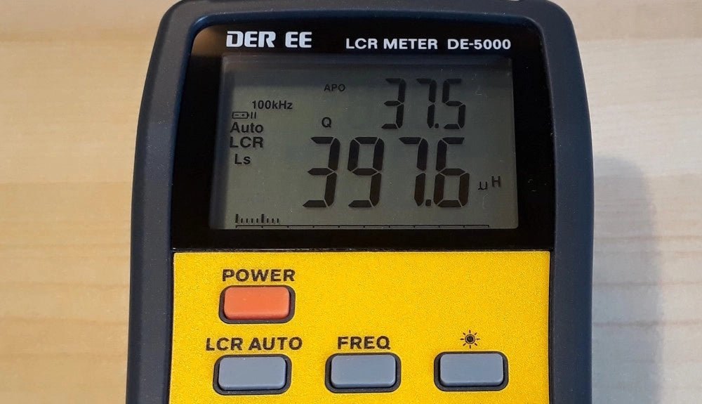
, by Jean-François Simon The DE-5000 LCR Meter (Review)
The DER-EE DE-5000 is a streamlined, portable LCR meter ideally suited for precise measurements of inductance, capacitance, and resistance in electronic components. Dive into its...
