
Search results for "elektor or special or power or supplies or and or batteries"
-
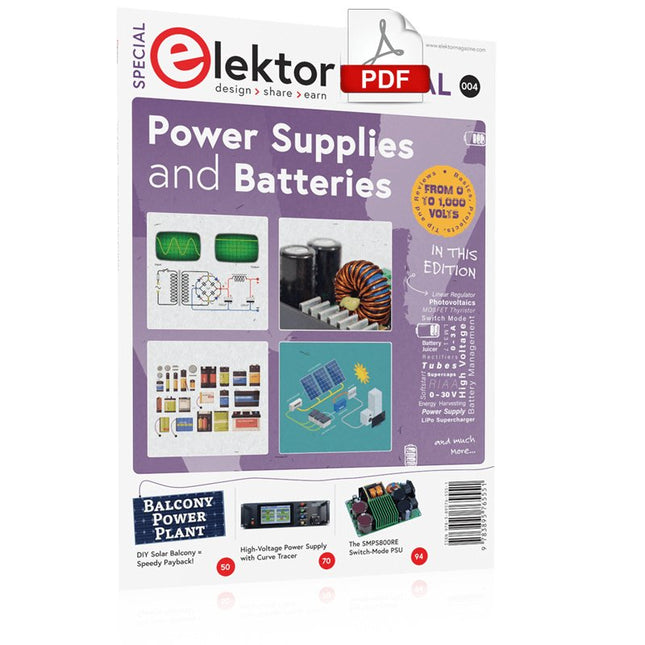
Elektor Digital Elektor Special: Power Supplies and Batteries (PDF)
Whatever the methods or even then financial means you have to make your circuits work, the power supply should rank high if not Number One in your considerations. The design block simply called “power supply” is hugely underrated both in electronics creation and repair. Yet, the “PSU” has enormous diversity and comes in wildly differing guises like AC/DC, generator, battery (rechargeable or not), PV panel, benchtop, linear or switch-mode, to mention but a few. The output ranges are also staggering like nano-amps to kiloamps and the same for voltages.This special covers the features and design aspects of power supplies.ContentsBasics Battery ManagementWhat to be aware of when using (Lithium) batteries. Fixed-Voltage Power Supply using Linear RegulatorsThe best result right after batteries. Light Energy HarvestingA small solar panel is used in an energy harvesting project to manage and charge four AAA cells. Mains Powered Adapter DesignBasic circuits and tips for transformers, rectification, filtering and stabilization. LM317 Soft StartThe high inrush current pulse should be avoided. Controllable RectifiersSome suggestions to keep the power loss in the linear regulator as low as possible. Components Worksheet: The LM117 / LM217 / LM317 Voltage Regulators SupercapsLow voltage but lots of current… or not? Reviews JOY-iT RD6006 Benchtop Power Supply Kit Siglent SDL1020X Programmable DC Electronic Load Projects Balcony Power PlantDIY solar balcony = speedy payback! DIY LiPo Supercharger KitFrom handcrafted to mass market Dual-Anode MOSFET ThyristorFaster and less wasteful than the old SCR Battery JuicerDo not throw away, squeeze! High-Voltage Power Supply with Curve TracerGenerate voltages up to 400 V and trace characteristics curves for valves and transistors High Voltage Supply for RIAAFor RIAA tube preamps and other applications. MicroSupplyA lab power supply for connected devices Phantom Power Supply using Switched CapacitorsVoltage tripler using three ICs The SMPS800RE Switch-Mode Supply for the Elektor Fortissimo-100Reliable, light and affordable Soft Start for PSUBe nice to your power supply – and its load UniLab 20-30 V, 3 A compact switch-mode lab power supply Tips Soft Start for Step-Down Switching Regulators Low Loss Current Limit Powerbank Surprise A Virtual Ground Battery Maintainer Battery Pack Discharger Connecting Voltage Regulators in Parallel
€ 11,95
Members: € 10,76
-

Elektor Labs Elektor Low-Noise Lab Power Supply
The Elektor Low-Noise Lab Power Supply is a fully analogue, adjustable, medium-power symmetrical bench supply that contains no switching or digital components. It provides an output voltage adjustable between 0 V and ±22 V, and an output current adjustable from 0 A to 1 A. Because it avoids any form of switching circuitry, the design delivers extremely low noise. To display both output voltages and currents, four miniature moving-coil panel meters are used. Most modern laboratory power supplies and AC adapters employ switch-mode techniques. Even the best examples inevitably exhibit high-frequency ripple and other switching artefacts on their output, which can interfere with the testing of sensitive analogue circuits and disturb low-level measurements. To overcome this, the concept here is a completely analogue power supply. Although less efficient than its switch-mode counterparts, the reduced efficiency is of little importance for test-bench use and ensures cleaner, more reliable measurement results. Because many analogue circuits require a symmetrical supply, this design delivers positive and negative output voltages of equal magnitude. A small amount of adjustment is available to compensate for any imbalance. Naturally, a variable current-limit function is also included. The kit includes the components required to build the power supply, except for the transformers. Specifications Output Voltage 0…+22 V, 0, −22 V Output Current 0…+1 A, 0…−1 A Noise −85 dBV, (at 0.95 A/20 V, B = 22 kHz) −84 dBV (at 0.95 A/20 V, B > 500 kHz) Ripple 50 µVRMS (at 950 mA/20 V, B = 22 kHz, mainly 100 Hz component) Included 3x PCBs: Regulator (PCB-1), Mains Filter (PCB-2) and Transformer (PCB-3) All the components except the AC transformers 4x moving-coil meters Additional parts for wiring (wires, banana sockets, IEC Power entry module, etc.) Not included The three AC transformers An enclosure Parts List For the Regulator PCB (240386-1) Resistors (250 mW, 1%) R1 = 12 Ω R2, R8, R37, R62 = 1 MΩ R3, R7, R10, R13, R17, R20, R22, R30, R35, R42, R45, R47, R55, R60 = 100 Ω, 600 mW R4, R5 = 4.7 kΩ R6 = 100 kΩ R9, R12, R14, R36, R38, R39, R61, R63, R66, R72, R78, R79 = 10.0 kΩ, 600 mW R11 = 9.76 kΩ, 600 mW R15, R40 = 44.2 kΩ, 600 mW R16, R41, R77 = 1 kΩ R18, R43 = 1.5 kΩ, 1 W, 5% R19, R44 = 470 Ω, 1 W, 5% R21, R46 = 330 Ω, 600 mW R23, R24, R48, R49 = 1.0 Ω, 1 W R25, R50 = 1 kΩ, 1 W, 5% R26, R28, R51, R53 = 1.000 kΩ 0.1%, 15 ppm/C R27, R29, R52, R54 = 10.00 kΩ 0.1%, 15 ppm/C R31, R56 = 1.2 kΩ, 1 W, 5% R32, R57 = 47 kΩ R33, R58 = 270 Ω R34, R59 = 27 kΩ R64, R69 = 12.0 kΩ R65 = 3.0 kΩ, 600 mW R67, R80 = 470 Ω, 600 mW R68, R70 = 6.8 kΩ, 600 mW R71 = 30.0 kΩ,, 600 mW R73, R74, R75, R76 = 10 MΩ P1, P2, P3 = 10 kΩ, 200 mW, 20%, potentiometer, 1 turns, single, lin., panel mount P4, P5 = 500 Ω, 500 mW, 10%, trimmer, 25 turns, 3296Y-1-501LF Bourns P6, P7 = 10 kΩ, 500 mW, 10%, trimmer, 25 turns, 3296Y-1-501LF Bourns Capacitors C1 = 100 nF, 50 V, 10%, ceramic X7R, LS 5 mm C2, C3, C6, C7, C30 = 10 µF, 63V, 20%, LS 2.5 mm, 3000hours@105°C C4, C5, C8, C9, C13, C14, C18, C19, C23, C24, C28, C29, C31, C32, C38, C39 = 100 nF, 250 V, 10%, PET, LS 7.5 mm C10, C20 = 47 nF, 100 V, 5%, PET, LS 5 mm C11, C21 = 10 nF, 100 V, 5%, PET, LS 5 mm C12, C22 = 220 µF, 35 V, 20%, 0.024 Ω, LS2.5/3.5 mm, Ir 3.4 A, 2000hours@125°C, polymer C15, C25 = 120 µF, 50 V, 20%, ESR 0.02 Ω, Diam. 10 mm max., LS 5 mm C16, C26 = 15 nF, 100 V, 5%, PET, LS 5 mm C17, C27 = 47 nF, 100 V, 5%, PET, LS 5 mm C33, C34 = 22 µF, 50 V, 20%, LS 2 mm, 10000 hours @ 105°C C35, C36, C44, C45 = 1 µF, 100 V, 10%, LS 5 mm, ceramic X7R C37 = 100 uF, 50 V, 20%. LS 3.5 mm C40, C41, C42, C43, C46, C47, C48, C49 = 1000 µF, 50 V, 20%, LS 5/7.5 mm, Ir 3.32 A, 10000hours@105°C, D 16 mm C50, C51, C52, C53 = 47 nF, 100 V, 10%, ceramic X7R, LS 5 mm Inductors L1, L2 = 4.7 µH, 3.2 A, 0.033 Ω, LS 5 mm, RLB0914-4R7ML Bourns L3 = Commom mode choke, 14.5 mH, 3 A, SSRH24NH-30145 Kemet Semiconductors D1, D2, D3, D4, D5, D9, D10, D11, D15 = BAT85, DO-34 D6, D7, D12, D13 = SR560, DO-201AD D8, D14, D16 = 1N4148, DO-35 D17 = Zenerdiode, 5.6 V, 0.5 W, DO-41 D18, D19 = 1N4004, DO-41 D20, D21 D22, D23 = V30100CI-M3/P, dual common cathode, TO-220 D24 = Zener diode, 30 V, 1 W, DO-41 LED1, LED2 = LED, red, T-1 (3 mm) LED3, LED4 = LED, green, T-1 (3 mm) TVS1, TVS2 = BZW50-33B, R6 T1, T2, T4 = BC337.25, TO-92 T3 = NJW0302G, TO-3P T5, T6, T8 = BC327.25, TO-92 T7 = NJW0281G, TO-3P T9 = BD139, TO-126 (SOT-32) IC1 = LM334Z, TO-92 IC2 = LM4040AIZ-5.0/NOPB, TO-92 (TO-226AA-3) IC3, IC4 = OPA2992IDR, SOIC-8 IC5, IC6 = OPA4992IDR, SOIC-14 IC7 = OPA992IDBVR, SOT-23-5 IC8 = LM339N, DIP-14 IC9 = LM317, TO-220 IC10 = LM337, TO-220 Others F1, F2 = 5×20 mm fuse, 1.6 A, fast acting HS1, HS2 = Heatsink MC33271 (for T3/T7), 2.7°C/W, PCB mount, height 63.5 mm K1, K4 = 3-way screw terminal block, LS 3.5 mm, max. 1.5 mm² K2, K3 = 3-way screw terminal block, LS 3.5 mm, max. 1 mm² M1, M3 = Moving coil meter, Range 30 V, type 91C4, 45×45 mm M2, M4 = Moving coil meter, Range 1 A, type 91C4, 45×45 mm² RE1 = Relay DPDT,5V, UA2-5NU Miscellaneous 3× 3-way screw terminal block, LS 3.5 mm, max. 1 mm² (for P1, P2, P3) 4× Pin header, 1×2, vertical, pitch 2.54 mm (for LED1, LED2, LED3, LED4) 4× Pin socket, 1×2, vertical. pitch 2.54 mm (for LED1, LED2, LED3, LED4) 2× Heatsink FK222SA220, 20°C/W, PCB mount (for IC9 & IC10) 2× Mica thermal pad for TO-220, 12×18×0.05 mm (for IC9 & IC10) 2× Insulating bushing IB 6, TO-220 (for IC9 & IC10) 2× Ceramic thermal pad, 23×20×2 mm (for T3 & T7) 2× PCB Fuse Holder, for 5×20 mm fuse, 10 A (for F1, F2) 2× Cover for PCB Fuse Holder, transparent (for F1, F2) 2× 2-way screw terminal block, LS 3.5 mm, max. 1 mm² (for M1 & M3) 2× 2-way screw terminal block, LS 3.5 mm, max. 1.5 mm² (for M2 & M4) 8× M3 solder lug, thickness 0.35 mm (for M1…M4) M4 solder lug, thickness 0.35 mm (to connect 4 mm banana connectors) Screened cable, 1 pair, 2×24 AWG/0.22 mm², 1 m (for P1, P2 & P3) IC socket, DIP, 14 contacts (for IC8) M3 washer, plain, steel M3 screw, 16 mm, steel, pan head M3 nut M3 spring washer 50 mm M3 standoff, steel, male-female 12 mm M3 standoff, steel, male-female 10 mm M3 standoff, steel, male-female M3 screw, 8 mm, steel, pan head For the Mains Fiter PCB (240386-2) Resistor R1 = 220 kΩ, 1 W, 500 V, 5% Capacitors C1, C2 = 470 nF, 305 VAC, Class X2, 11 × 27 mm max., LS 15/22.5 mm C3, C4, C5, C6 = 2.2 nF, 300 VAC, Class Y2, 13 × 4 mm, LS 10 mm, PP Inductors L1, L2 = Common-mode choke, 6.8 mH, 1.7 A, TDK B82732R2172B030 Semiconductor MOV1 = TVS varistor, 300 VAC, S14K300 (230 VAC, B72214S0301K101) and SK14K150 (150 VAC, B72214S0151K101) Others K1, K2 = 3-way screw terminal block, LS 7.62 mm F1 = Time-delay fuse, 0.5 A (230 VAC) or 1 A (115 VAC) Miscellaneous 1× Fuse holder, 5×20 mm, 10 A, 500 VAC 1× Transparent fuse cover 4× 10 mm M3 standoff, steel, male–female 4× M3 screw, 8 mm, steel, pan head 4× M3 nut For the Transformer PCB (240386-3) Resistors R1, R2 = 2.7 kΩ, 600 mW, 1% R3 = 10.0 kΩ, 600 mW, 1% Capacitor C1 = 220 µF, 50 V, 20%, Ø10 mm, LS 5 mm, 4000 h @ 105°C Transformers (not included in this kit!) TR1, TR2, TR3 = 2×7 V, 25 VA, PCB-mounted toroid, 70060K Talema Semiconductors D1–D4 = 1N4148, DO-35 D5, D6 = 1N4004, DO-41 D7 = Zener 5.6 V, 1.3 W, DO-41 LED1 = LED, red, T-1 (3 mm) IC1, IC2 = MOC8021M, CTR ≥ 1000%, DIP-6 Others F1, F2, F3 = 160 mA time-delay fuse (230 VAC) or 315 mA time-delay fuse (115 VAC) K1 = 2-way screw terminal block, LS 7.62 mm K2 = 3-way screw terminal block, LS 3.5 mm, max 1.5 mm² K3, K4 = 3-way screw terminal block, LS 3.5 mm, max 1 mm² RE1, RE2 = Relay DPDT, 5 A/250 VAC / 24 VDC Miscellaneaous 1× Pin header 1×2, pitch 2.54 mm + matching socket for LED1 3× Fuse holder 5 × 20 mm, 10 A, 500 VAC + transparent cover 3× M4 screw, 8 mm, pan head + washer for TR1-TR3 8× M3 screw, 8 mm, pan head + nut + washer 8× 10 mm M3 standoff, steel, male–female 2× IC socket, DIP-6 for IC1 & IC2 Additional Parts 1 m red insulated wire, stranded, 1.5 mm² 0.5 m blue insulated wire, stranded, 1.5 mm² 0.5 m black insulated wire, stranded, 1.5 mm², 0.5 m 2 m red insulated wire, stranded, D 0.56 mm (0.25 mm²) 2 m black insulated wire, stranded, D 0.56 mm (0.25 mm²) 0.5 m Multicore Cable, Flexible, 3 Core, 0.75 mm² (24 x 0.2 mm) Red banana socket Black banana socket Blue banana socket Green banana socket IEC Power Entry Module with switch, IEC C14 3 crimp terminals, FASTON, 4.75 x 0.81 mm 3 knobs Links Elektor Labs JumpStarter Page Article (Part 1) Article (Part 2)
€ 299,00€ 249,00Best Price
-

Elektor Digital Elektor Circuit Special 2026 (PDF) EN
Elektor GREEN and GOLD members can download their digital edition here. Not a member yet? Click here. A Current Source for Testing (Z-)DiodesChecking Z-Diodes from 1 to 54 V @ 1 to 50 mA ESD Strap TesterA Bench Tool with Pass, Borderline, and Fail Indication Power Supply Transient Response TesterA Repeatable Step-Load Generator for Bench Power Supplies Euclidean Sequencer Without a MicrocontrollerTrigger Patterns and CV Sequences with Simple CMOS Logic LED Flashing Light for Gates and More with an Audible Alert Need PCBs? The Elektor PCB Service Has You Covered. Toothbrush TimerUsing a Tiny PIC A Contactless Magnetic Combination LockWith the AS5600 Rotary Position Sensor Low-Noise Battery-Powered PreamplifierFor Dynamic Microphones The Arduino Nano TestLabMeasurement, Control, and Regulation Rhythmic Bass LightEmphasize the Rhythm of Your Music Low-Cut FilterNo Risk of Audio Feedback on Your System Precise 1 Hz Square Wave Generator for BreadboardsA Reliable CMOS-Based Clock Source 555 Upside DownDuty Cycles Down to Zero From Halfgeleidergids to Circuit Specials65 Years of Electronics Innovation Electrical IsolationCAN Interface with Digital Isolator and Power Module SpongillatorA Sponge-Based Oscillator True Random Number GeneratorWith Integrated Chi-Square Test 3D Viewer for HTML pagesSimple, and Almost Without Code Programming with TLScriptA Scripting Language for Measurement, Testing, and Control Circuit Design: Tips from Experts FeedbackWhat Is It and Why Is It Important? One Board, Endless Ideas: Arduino UNO QFrom Retro Gaming to Real-Time Environmental Monitoring How to Fix a Donut Antenna Standby KillerA Real On/Off Switch for Your TV Battery TestingMeasuring Batteries with the Arduino Nano Power Supply for Audio Power AmplifiersA Good Power Supply Without Mains Hum Prototyping Boards for RFFast Setups with DIY Prototyping Boards T3 Surge ProtectionA Type 3 Spike Suppressor for Your Sensitive Equipment IoT Room Thermostat BoardWith ESP32-C3/S3-Based Xiao MCU module From Rigid to SmartFlexible and Printed Electronics — Between Vision and Industrial Reality
€ 9,50
-
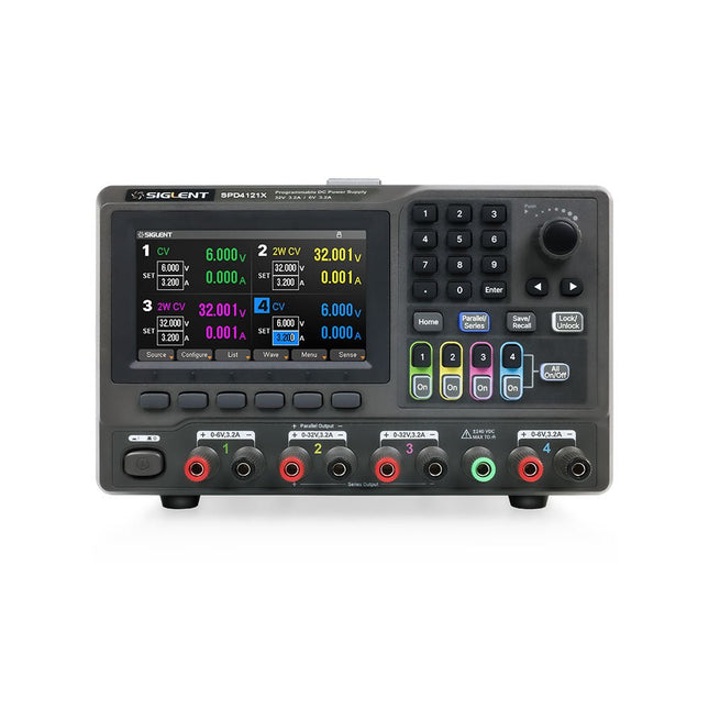
Siglent Siglent SPD4121X 4-ch DC Power Supply (285 W)
The Siglent SPD4121X is a 4-channel DC Linear Programmable Power Supply equipped with a 4.3-inch TFT-LCD display, friendly human-machine interface, and excellent performance indicators. Real-time waveform display provides engineers with an informative user interface. SPD4121X offers a total output power of 285 W with a resolution of 1 mV/1 mA. The maximum voltage and current for each channel are as follows: CH1: 15 V/1.5 A CH2: 12 V/10 A CH3: 12 V/10 A CH4: 15 V/1.5 A Features Rated output power: 285 W Rated voltage: 32 V, 12 V, 30 V Up to four high-precision power supplies with independent controllable outputs, supporting CH2 and CH3 series and parallel connections Clear graphical interface with waveform and timer display modes 5-digit voltage and current display with minimum resolution of 1 mV, 1 mA Fast output response time: <50us The high current channel support remote voltage compensation sense function. The maximum compensation voltage is 0.6 V Overvoltage protection and overcurrent protection or safe and accurate operation Equipped with a 4.3-inch TFT-LCD display (480 x 272 resolution) USB and LAN standard communication USB-GPIB module is optional Excellent channel density with up to 4 channels in a 3U half rack package Internal data storage for setups and parameters Embedded Web Server with instrument communication that doesn’t require software installation Fully SCPI programming command set support as well as a LabView driver for remote control and system automation Specifications SPD4323X SPD4121X SPD4306X Channel Output CH1: Voltage 0 to 6 V Current 0 to 3.2 ACH2: Voltage 0 to 32 V Current 0 to 3.2 ACH3: Voltage 0 to 32 V Current 0 to 3.2 ACH4: Voltage 0 to 6 V Current 0 to 3.2 A CH1: Voltage 0 to 15 V Current 0 to 1.5 ACH2: Voltage 0 to 12 V Current 0 to 10 ACH3: Voltage 0 to 12 V Current 0 to 10 ACH4: Voltage 0 to 15 V Current 0 to 1.5 A CH1: Voltage 0 to 15 V Current 0 to 1.5 ACH2: Voltage 0 to 30 V Current 0 to 6 ACH3: Voltage 0 to 30 V Current 0 to 6 ACH4: Voltage 0 to 15 V Current 0 to 1 A Resolution 1 mV, 1 mA 1 mV, 1 mA 1 mV, 1 mA Setting Accuracy Voltage: ±(0.03% of reading+10) mV, Current: ±(0.3% of reading+10) mA Voltage: ±(0.03% of reading+10) mV, Current: ±(0.3% of reading+10) mA Voltage: ±(0.03% of reading+10) mV, Current: ±(0.3% of reading+10) mA Readback Accuracy Voltage: ±(0.03% of reading+10) mV, Current: ±(0.3% of reading+10) mA Voltage: ±(0.03% of reading+10) mV, Current: ±(0.3% of reading+10) mA Voltage: ±(0.03% of reading+10) mV, Current: ±(0.3% of reading+10) mA Display 4.3" TFT-LCD 5-digit voltage and current display 4.3" TFT-LCD 5-digit voltage and current display 4.3" TFT-LCD 5-digit voltage and current display Output power 240 W 285 W 400 W Included 1x Siglent SPD4121X Power Supply 1x Power cord (EU) 1x Output test cord (3 A) 1x USB cable 1x Quick start guide Downloads Datasheet Manual Quick start
€ 871,20
-

Elektor Classics The Elektor Power Supply Collection 2026 (USB Stick)
More than 275 Power Supply Designs for Home Construction This USB Stick contains over 275 different power supply circuits from the volumes 2001-2025 of Elektor. The article search feature allows you to search full-text content. The results are always displayed as pre-formatted PDF documents. Highlights Cuk Converter Automatic Battery Switchover Battery Voltage LED Digital Benchtop Power Supply Lithium-Ion Charger Solar Cell Charger Electronic Fuse High Voltage Regulator Power Supply for USB Devices Step-up Converter for LEDs Battery Management and much more... On the Stick you will also find a folder with additional material such as PCB layouts, Gerber files and software. Specifications Storage 16 GB Interfaces 1x USB-A1x USB-C System requirements PC with Adobe Reader 7.0 or higher Web browser
€ 49,95€ 39,95Best Price
-

Elektor Classics The Elektor Circuit Collection 2026 (USB Stick)
3K5 Noteworthy Designs (1975-2026) This USB archive stick contains over 3,500 noteworthy circuits from all areas of electronics (audio & video, hobby & modelling, home & garden, test & measurement, computers & microcontrollers, radio, power supplies & batteries) published in Elektor Magazine since 1975. Most circuits are sourced from the Elektor Summer Circuits editions. You can use the article search function to find specific content in the full text. The results are always shown as preformatted PDF documents. Adobe Reader may be used to browse articles as well as find individual words and expressions using the program’s integrated Search functions. Please note that no Summer Circuits editions were published between 2014 and 2022, so these years are not included in the directory. Specifications Storage 16 GB Connectors 1x USB-A1x USB-C
€ 49,95€ 39,95Best Price
-
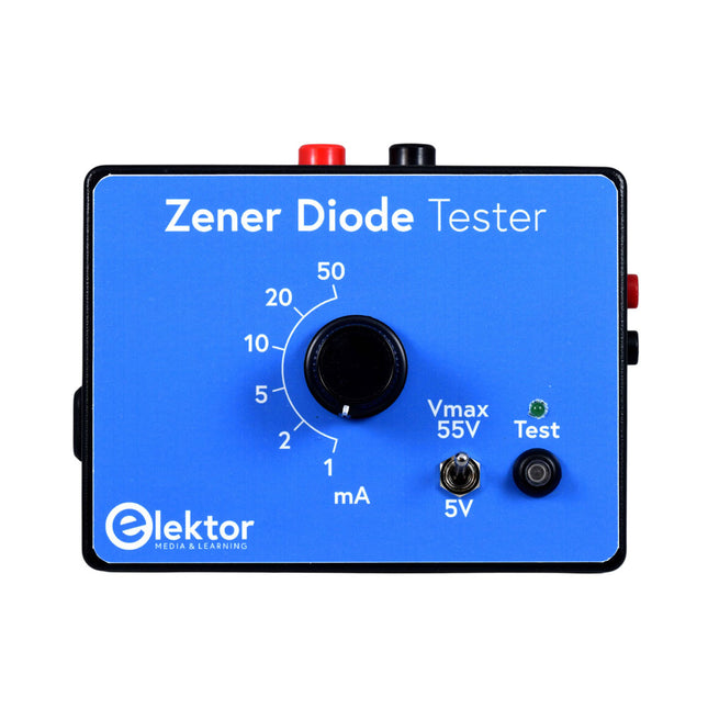
Elektor Zener Diode Tester
The Elektor Zener Diode Tester is essentially a constant-current source that can be switched in steps from 1 to 50 mA. It can be used to test Z-diodes up to a maximum of 54 V. Thanks to a 60-V step-up converter, the device can be powered by the usual 5 to 12 V. The principle of this tester is straightforward. A Z-diode or other DUT (device under test, such as an LED) is biased by an adjustable current source. The voltage across the DUT can be measured with a multimeter. The voltage of most (small) Z-diodes is specified at a current of 5 mA. Depending on the application, the voltage at other currents can also be of interest. That is why six current settings are available: 1, 2, 5, 10, 20, and 50 mA. LEDs are often specified at a current of 20 mA. What can be tested is: Whether a Z-diode is defective (short circuit or high impedance). Whether a Z-diode exhibits the correct Z-voltage. How a Z-voltage changes with different currents. What exact voltage is present at an integrated voltage reference. Whether LEDs in a series chain differ in brightness (hence the 20 mA current). What the current gain is for different base currents in (power) transistors. The kit contains all parts listed in the bill of materials including PCB and enclosure. Specifications Supply voltage 5…12 V/2 A (USB-C) Supply current (Itest = 50 mA) 1.1 A @ 5 V / 412 mA @ 12 V Selectable currents 1, 2, 5, 10, 20, and 50 mA Max. test voltage >54 V @ Itest ≥1 mA Max. output voltage 60 V @ Itest = 0 mA Voltage limit at 5 V 4.5 V @ Itest = 1 mA / 5.18 V @ Itest = 50 mA Enclosure dimensions 110 x 82 x 44 mm PCB size 105.4 x 67.3 mm Connections 4 mm banana sockets for multimeter 2 mm banana sockets for test clips USB-C socket for power supply Included Resistors R1 = 3.3 kΩ, 600 mW, 1% R2 = 0.15 Ω, 1 W, 5%, LS 12.7 mm, ø 3.5 mm R3, R8 = 180 Ω, 600 mW, 1% R4, R6, R16 = 1 kΩ, 600 mW, 1% R5, R19 = 47 kΩ, 600 mW, 1% R7 = 3.9 kΩ, 1 W, 5%, LS 12.7 mm, ø 3.5 mm R9, R10, R12 = 10 kΩ, 600 mW, 1% R11, R13 = 100 Ω, 600 mW 1% R14 = 249 Ω, 600 mW, 1% R15 = 499 Ω, 600 mW, 1% R17 = 2.49 kΩ, 250 mW, 1% R18 = 4.99 kΩ, 250 mW, 1% Capacitors C1 = 470 uF / 35 V, 20%, Ir = 1.86 A, ø 12.5 mm, LS 5 mm, ESR = 0.038 Ω (Panasonic EEUTP1V471) C2 = 1 uF / 100 V, 10%, X7R, LS 5 mm C3 = 2.2 nF / 50 V, 10%, X7R, LS 5 mm C4, C7 = 100 nF / 100 V, 10%, X7R, LS 5 mm C5 = 100 uF / 100 V, 20%, ø 14 mm max., LS 5 mm C6 = 1 nF / 100 V, 10%, X7R, LS 5 mm Inductor L1 = 100 uH, Irms = 2.4 A, Isat = 3.5 A, 0.09 Ω, radial, pitch 2.5/5/10 mm, ø 14 mm max. (Kemet SBC8-101-242) Semiconductors D1 = MUR120G, DO-41 D2, D4 = STPS3150RL, DO-201AD D3 = Z-diode, 18 V, 1.3 W (BZX85C18) D5 = Z-diode, 5.1 V, 0.5 W (1N5231B) LED1 = LED in pushbutton S1 LED2 = LED, green, 3 mm IC1 = MC34063, DIP-8 IC2 = LM4040BIZ-5.0/NOPB, TO-92 (TO-226AA-3) IC3 = TL051CP, DIP-8 T1 = BC327.25, TO-92 T2 = STP40NF10L, TO-220 T3 = IRF9510PBF, TO-220 T4 = 2N7000, TO-92 Others K1, K2, S1, S3 = 2-way screw terminal block, LS 3.5 mm, max. 1.5 mm² connected to K1 = USB-C socket, 30 V/3 A, chassis mounted, wired, 9 x 16 mm connected to K2 = Banana Connector, 2 mm, Socket, 60 VDC, Panel Mount, red (Multicomp 24.102.1) connected to K2 = Banana Connector, 2 mm, Socket, 60 VDC, Panel Mount, black (Multicomp 24.102.2) Test clip, red, 30 VAC/60 VDC (Hirschmann 931467101) Test clip, black, 30 VAC/60 VDC (Hirschmann 931467100) S1 = Pushbutton, panel mount, SPST-NO, 30 DC/100 mA, with red LED S2 = Rotary Switch, 6 position, 2 pole, 30°, 250 V/150 mA S3 = Toggle switch, panel mount, SPDT, solder lugs, 28 VDC T2, T3 = Heat sink, 15°C/W, FK 214 SA-CB Enclosure Hammond 1591XXSSBK, ABS, 110 x 82 x 44 mm Knob for S2, round shaft 6 mm, ø 21 mm, with indicator line (Multicomp CP-LB21-6-6D) 4 x Self-tapping screw #4-1/4", carbon steel, pan head Banana plug, red, 2 mm, 60 VDC (Multicomp 25.205.1) Banana plug, black, 2 mm, 60 VDC (Multicomp 25.205.2) Banana socket, black 4 mm, panel mount Banana socket, red 4 mm, panel mount for LED1, LED2 = Pin header, 1 x 2, vertical, pitch 2.54 mm for LED1, LED2 = Pin socket, 1 x 2, vertical, pitch 2.54 mm for T2, T3 = M3 screw, 10 mm, steel, pan head 2 x M3 washer, plain, steel 4 x M3 nut for IC1, IC3 = DIP-8 socket Wire, black, 0.25 mm² (24 AWG), stranded 14 x 0.15 mm, 1 m Wire, red, 0.25 mm² (24 AWG), stranded 14 x 0.15 mm, 1 m PCB 250772-1 v1.1 Links Article Elektor Labs
€ 99,95€ 79,95Best Price
-
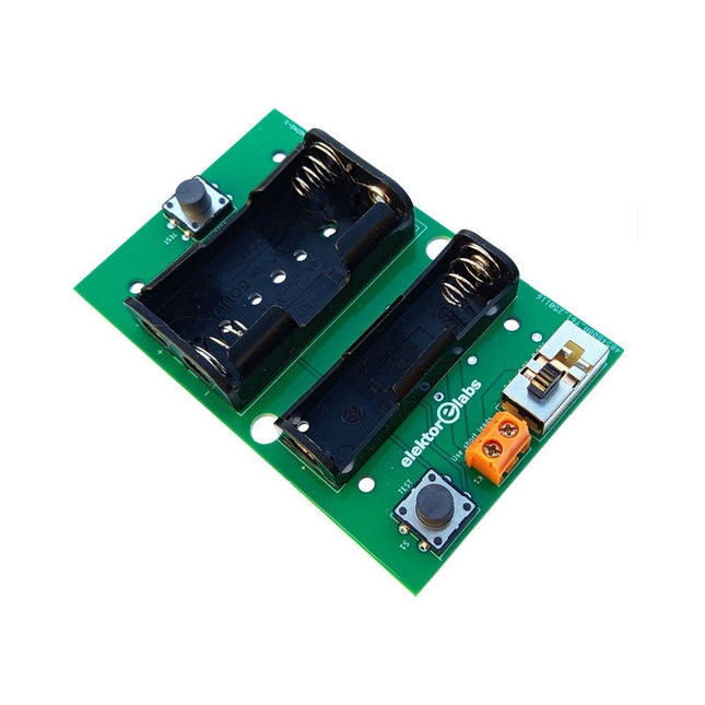
Elektor Labs Elektor Milliohmmeter Adapter
The Elektor Milliohmmeter Adapter uses the precision of a multimeter to measure very low resistance values. It is an adapter that converts a resistance into a voltage that can be measured with a standard multimeter. The Elektor Milliohmmeter Adapter can measure resistances below 1 mΩ using a 4-wire (Kelvin) method. It is useful for locating short circuits on printed circuit boards (PCB). The adapter features three measurement ranges – 1 mΩ, 10 mΩ, and 100 mΩ – selectable via a slide switch. It also includes onboard calibration resistors. The Elektor Milliohmmeter Adapter is powered by three 1.5 V AA batteries (not included). Specifications Measurement ranges 1 mΩ, 10 mΩ, 100 mΩ, 0.1% Power supply 3x 1.5 V AA batteries (not included) Dimensions 103 x 66 x 18 mm (compatible with Hammond 1593N-type enclosure, not included) Special feature On-board calibration resistors Downloads Documentation
€ 34,95
Members: € 31,46
-

Elektor Digital Elektor Special: Stromversorgung & Batterien (PDF)
Der simpel „Stromversorgung“ genannte Schaltungsteil wird sowohl bei der Entwicklung als auch bei der Reparatur von Elektronik enorm unterschätzt. Dabei ist die Vielfalt bei Netzteilen oder neudeutsch „PSU“ enorm. Es gibt sie in den unterschiedlichsten Ausführungen: mit Gleich- oder Wechselspannung, als Generator, Akku oder Batterie, als Solar-Panel, extern oder eingebaut, linear oder „geschaltet“ – um nur einige zu nennen. Auch die Leistungsbereiche sind enorm: von Nano-Ampere bis Kilo-Ampere – dasselbe gilt für Spannungen. Bei der konkreten Umsetzung kann man zwischen ICs oder diskreten Bauteilen, zwischen fertigem Gerät bzw. Modul oder der Realisation aus selbstverlöteten Bauteilen wählen. Dieses Special deckt die wichtigsten Merkmale und Gestaltungsaspekte von Stromversorgungen ab. Inhalt Grundlagen BatteriemanagementWas man beim Einsatz von (Lithium-)Akkus beachten muss. Festspannungsnetzgerät mit LinearreglerDas beste Ergebnis gleich nach den Batterien. Lichtenergie sammelnWie man ein Solarmodul für ein Energy-Harvesting-Projekt verwenden kann. Netzbetriebene VersorgungsgeräteBasis-schaltungen und Tipps für Transformatoren, Gleichrichtung, Siebung und Stabilisierung. SanftanlaufDer hohe Einschaltstrompuls sollte vermieden werden. Steuerbare GleichrichterEinige Vorschläge um die Verlustleistung im Längsregler möglichst gering zu halten. Komponenten Arbeitsblatt: Spannungsreglerserie LM117 / LM217 / LM317 Supercaps Reviews Labornetzteil-Kit Joy-iT RD6006 Elektronische Last Siglent SDL1020X-E Projekte Balkon-KraftwerkSelbst installiert = schnell amortisiert! DIY-LiPo-Supercharger-KitVom Prototyp zum Massenmarkt. Doppelanoden-MOSFET-ThyristorSchneller und effizienter als herkömmliche SCRs. Batterie-EntsafterNicht wegwerfen, ausquetschen! Hochspannungsnetzteil mit KennlinienschreiberSpannungen bis 400 V einstellen und Kennlinien für Röhren und Transistoren erstellen. HochspannungsnetzteilFür RIAA-Röhrenvorverstärker und andere Anwendungen. MicroSupplyEine Laborstromversorgung für universelle Anwendungen. Phantom-Speisung mit geschalteten KondensatorenSpannungsverdreifachung mit zwei ICs. Das SMPS800RE Schaltnetzteil für den Elektor Fortissimo-100Zuverlässig, leicht und erschwinglich. SoftstartSchont das Netzgerät und die Last. UniLab 2Geschaltetes Labornetzteil 0…30 V/3 A Tipps Softstart für Step-Down-Schaltregler Stromabschaltung mit minimalen Verlusten Powerbank-Geheimnisse Künstliche Masse Akku-Erfrischer Akkupack-Entlader Parallelschaltung von Spannungsreglern
€ 11,90
Members: € 10,71
-
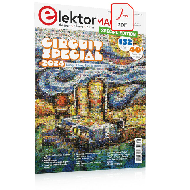
Elektor Digital Elektor Circuit Special 2024 PDF (EN)
Elektor GREEN and GOLD members can download their digital edition here. Not a member yet? Click here. Digital Load for High-Current TestingFrom Necessity to Innovation Vocal RemoverInstant Karaoke Circuit Audio A/B Selector With Gain ControlSwitches from Microphone to Line Inputs Better Charging for the LIR2032Be Kind to Your Coin Cells Touch Sensing Made SimpleA DIY Guide for Any Microcontroller Universal Infrared Remote SwitchA New Life for Old Remotes Microcontroller-Powered Moo BoxMaking Playful Sounds With a Microcontroller USB Battery Interface Powering Low-Draw Devices With Power BanksA “Stay Alive” Solution Small Class-A Audio Amplifier With Current OutputDrive Speakers with Current Instead of Voltage Pseudo-Balanced ModuleHigh CMRR with Unbalanced Audio Links Ni-MH Cells Automatic ChargerRefill All Your Battery Packs in One Go! Thyristor-Based Power Supply Protection Fingerprint Sensor SwitchA Useful Proof-of-Identity Device DC-DC 3-A Power ConverterUpgrade Your Fixed-Voltage Sources Remote Water Heater MonitorVoltage and Current Detection for AC Lines Attenuators for Audio Signals (1)Adjustable Via Jumpers Pimp My Car Battery Charger (Part 1)Don’t Throw It Away, Mod It! A Board for the Blue OnePCB for Alps Motorized Potentiometer with Feedback 50-Hz Reference from 60-Hz Mains VoltageHow to Use 50-Hz Electronics in 60-Hz Environments Digital IsolatorsRealizing Galvanic Isolation Easily Compact 12-W Hi-Fi Mono AmplifierSmall But Powerful LM386 Ramp Generator Three-Phase GeneratorWith Raspberry Pi Pico Door Opener for the Musically Talented Elektor Classic: Surf SynthesizerOcean Watersports Background Sound Generator (OWBSG) Pimp my Car Battery Charger (Part 2)Don’t Throw It Away, Mod It! Lamp Current MonitorWith a Raspberry Pi Pico Infrared Telegraphy Fnirsi SWM-10Repair Battery Packs With This Portable Intelligent Spot Welding Machine Stereo Audio Codec for the ESP32 and Co.No Need to Be Afraid of Audio Measurement Technology Tin Soldering TechniquesMake Them Well Right Away! Attenuators for Audio Signals (2)Switching Via Relays USB-C PowerDrawing Power from USB-C Power Adapters Three Circuits with Two and Three Counter ICs4017 ICs Working Together Active Components – The Diode A Timer For Ultra-Long DelaysSet It, and Forget It! Jack In and Jack OutA Useful Insert Option for Audio Circuits Power an ESP32 from a Single Li-ion Cell Hexadoku
€ 7,50
-

Elektor Bundles 555-Timer-Projekte (Bundle)
Dieses Bundle befasst sich mit der Entwicklung von Projekten, die auf dem 555-Timer-IC basieren. Das Buch enthält über 45 vollständig getestete und dokumentierte Projekte. Zusammen mit dem Kit, das mehr als 130 durchkontaktierte Bauteile enthält, können Sie alle beschriebenen Projekte auf einem Breadboard nachbauen. Der Aufbau macht es auch einfach, die Projekte zu modifizieren und mit ihnen zu experimentieren. Über 45 Projekte für den legendären 555-Chip (und den 556, 568) Einige der Projekte im Buch sind: Abwechselnd blinkende LEDs Veränderung der Blinkrate von LEDs Touchsensor-Ein/Aus-Schalter Ein-/Ausschaltverzögerung Lichtabhängiger Ton Dunkel-Hell-Lichtschalter Tonburst-Generator Langzeit-Timer Lauflichter LED-Roulette-Spiel Ampelsteuerung Durchgangsprüfer Elektronisches Schloss Kontaktentprellung für Schalter Spielzeug-Elektronikorgel Mehrfachsensor-Alarmsystem Metronom Spannungsmultiplizierer Elektronischer Würfel 7-Segment-Display-Zähler Motorsteuerung 7-Segment-Display-Würfel Elektronische Sirene Verschiedene andere Projekte Inhalt des Kits Widerstände 1x 15 kΩ 1x 68 kΩ 2x 47 kΩ 1x 82 kΩ 2x 820 Ω 1x 8,2 kΩ 3x 10 kΩ 1x 1,8 kΩ 1x 6,8 kΩ 14x 2,2 kΩ 10x 680 Ω 1x 27 kΩ 1x 5,6 kΩ 1x 560 kΩ 1x 4,7 kΩ 1x 3,3 kΩ 3x 33 kΩ 1x 36 kΩ 2x 100 kΩ 5x 1 kΩ 1x 3,9 kΩ 2x 56 kΩ 2x 12 kΩ 1x 10 kΩ Potentiometer 1x 1 MΩ Potentiometer 2x 50 kΩ Potentiometer 3x 20 kΩ Potentiometer 1x 10 kΩ Potentiometer 1x 10 kΩ Potentiometer 1x 50 kΩ Potentiometer 1x 100 kΩ Potentiometer 1x 50 kΩ Potentiometer Kondensatoren 1x 0,33 μF 1x 1 μF 1x 10 nF 1x 22 nF 1x 47 nF 1x 100 nF 1x 10 μF electrolytisch 1x 33 μF electrolytisch 2x 100 μF electrolytisch LEDs 10x 5 mm rote LED 10x 3 mm rote LED 3x 3 mm gelbe LED 3x 3 mm grüne LED 1x 7-Segment-LED mit gemeinsamer Kathode Halbleiter 3x 555-Timer 1x CD4017 Counter 1x CD4026 Counter 1x CD4011 NAND-Gate 4x 1N4148 Diode 1x IRFZ46N MOSFET 1x Thermistor 1x Lichtabhängiger Widerstand (LDR) Sonstiges 1x Passiver Summer 1x Aktiver Summer 1x SG90-Servo 1x 8 Ω Mini-Lautsprecher 1x 9 V DC Bürstenmotor 1x 5 V Relais 1x 9 V Batterieclip 7x Drucktastenschalter 1x Breadboard 1x Breadboard-Überbrückungskabel
€ 69,95€ 54,95Best Price


-
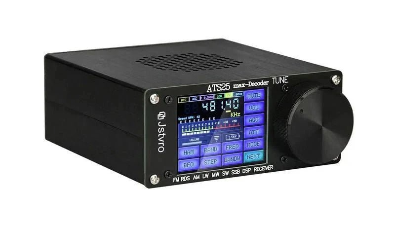
, by Jan Buiting Introducing the ATS25 Max: The Ultimate Ultra-Portable Decoder Receiver
Elektor proudly presents the ATS25 max-Decoder, a powerful yet ultra-compact multimode DSP receiver. This cutting-edge device offers comprehensive coverage of LW, SW, MW, FM, and...
