
Search results for "eagle OR 6 OR pcb"
-

Elektor Digital EAGLE V6 Getting Started Guide (E-book)
Whether you are an electronics enthusiast or engineering professional, this book provides the reader with an introduction to the use of the CadSoft’s EAGLE PCB design software package. EAGLE is a user-friendly, powerful and affordable software package for the efficient design of printed circuit boards. It offers the same power and functionality to all users, at a smaller cost than its competitors. A free version of EAGLE is available to enthusiasts for their own use. EAGLE can be used on the main computing platforms including: Microsoft Windows (XP, Vista or Windows 7); Linux (based on kernel 2.6 or above) and Apple Mac OS X (Version 10.6 or higher). Any hardware that supports these software platforms will run the EAGLE application. The book is intended for anyone who wants an introduction to the capabilities of EAGLE. The reader may be a novice at PCB design or a professional wanting to learn about EAGLE, with the intention of migrating from another CAD package. This book will quickly allow you to: obtain an overview of the main modules of EAGLE: the schematic editor; layout editor and autorouter in one single interface; learn to use some of the basic commands in the schematic and layout editor modules of EAGLE; apply your knowledge of EAGLE commands to a small project; learn more about some of the advanced concepts of EAGLE and its capabilities; understand how EAGLE relates to the stages of PCB manufacture; create a complete project, from design through to PCB fabrication. The project discussed in the book is a popular, proven design from the engineering team at Elektor. After reading this book while practicing some of the examples, and completing the projects, the reader should feel confident about taking on more challenging endeavors.
€ 29,95
Members: € 26,96
-
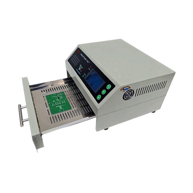
puhui Upgraded T-962 v2.0 Reflow Soldering Oven (Elektor Version)
This upgraded version 2.0 (available exclusively from Elektor) contains the following improvements: Enhanced protective earthing (PE) for furnace chassis Extra thermal insulation layer around furnace to reduce odors Connection to a computer, allowing curve editing on a PC Features such as constant temperature control and timing functions The infrared IC heater T-962 v2.0 is a microprocessor-controlled reflow oven that you can use for effectively soldering various SMD and BGA components. The whole soldering process can be completed automatically and it is very easy to use. This machine uses a powerful infrared emission and circulation of the hot air flow, so the temperature is being kept very accurate and evenly distributed. A windowed drawer is designed to hold the work-piece, and allows safe soldering techniques and the manipulation of SMDBGA and other small electronic parts mounted on a PCB assembly. The T-962 v2.0 may be used to automatically rework solder to correct bad solder joints, remove/replace bad components and complete small engineering models or prototypes. Features Large infrared soldering area Effective soldering area: 180 x 235 mm; this increases the usage range of this machine drastically and makes it an economical investment. Choice of different soldering cycles Parameters of eight soldering cycles are pre defined and the entire soldering process can completed automatically from Preheat, Soak and Reflow through to cool down. Special heat up and temperature equalization with all designs Uses up to 800 Watts of energy efficient Infrared heating and air circulation to re-flow solder. Ergonomic design, practical and easily operated Good build quality but at the same time light weight and a small footprint allows the T-962 v2.0 to be easily bench positioned transported or stored. Large number of available functions The T-962 v2.0 can solder most small parts of PCB boards, for example CHIP, SOP, PLCC, QFP, BGA etc. It is the ideal rework solution from single runs to on-demand small batch production. Specifications Soldering area (max) 180 x 235 mm (7.1 x 9.3") Power (max) 800 W Temperature range 0-280°C (32-536°F) Heating method Infrared Processing time 1~8 minutes Power supply 220 V AC/50 Hz Display LCD with Backlight Control mode 8 intelligent temperature curves Dimensions 310 x 290 x 170 mm (12.2 x 11.4 x 6.7") Weight 6.2 kg Included 1x T-962 v2.0 Reflow Soldering Oven (Elektor Version) 2x Fuses 1x Power cord (EU)
€ 349,00€ 299,00Best Price
-

Elektor Digital The EAGLE Companion (E-book)
EAGLE – the “Easily Applicable Graphical Layout Editor“ is a professional-grade CAD (computer aided design) software package for the design and drafting of electronic schematics as well as the design and fabrication of printed circuit boards (PCBs). This Advanced User Guide provides the experienced EAGLE user with insight into using some of the more advanced features of EAGLE software. It is not a guide to teach the reader the basic concepts of EAGLE, nor does it discuss the ‘how to’ of the EAGLE interface and the simpler operations and commands of the software. That is the purpose of the author’s previous title EAGLE V6 Getting Started Guide also published by Elektor. This eBook is intended as an enduring document covering the more advanced modules, commands, and functions which make up EAGLE. It is hoped that this eBook will provide a quick, succinct reference to assist with more complex applications and uses of EAGLE – an ‘EAGLE User’s Companion’, if you like. Complementing the EAGLE Advanced User Guide, the EAGLE User Language manual is included in this eBook in unabridged form, reproduced with permission of CadSoft GmbH. At the time of writing, the material in this eBook covers version 7 of the EAGLE software suite.
€ 39,95
Members: € 35,96
-

Great Scott Gadgets Great Scott Gadgets HackRF Pro SDR (100 kHz – 6 GHz) + FREE E-book
DEAL: Order the HackRF Pro now and get the new e-book "SDR with HackRF One & HackRF Pro" worth €20 for FREE! HackRF Pro is latest Software Defined Radio (SDR) from Great Scott Gadgets and the powerful successor to the legendary HackRF One. With a frequency range from 100 kHz to 6 GHz, it covers an enormous spectrum for transmitting and receiving radio signals. Designed as an open-source hardware platform, the HackRF Pro is the ideal tool for analyzing and developing modern wireless technologies. It can be used flexibly as a USB peripheral or programmed for standalone operation. Specifications Frequency: 100 kHz to 6 GHz Adjustable from 0 Hz to 7.1 GHz Half-duplex transceiver Up to 20 million samples per second 8-bit quadrature samples (8-bit I and 8-bit Q) Compatible with GNU Radio, SDR#, and more Software-configurable RX and TX gain and baseband filter Software-controlled RF port power (50 mA at 3.3 V) SMA RF connector SMA clock input and output for synchronization and triggering Convenient buttons for programming Internal pin headers for expansion High-Speed USB 2.0 with USB-C connector USB-powered Open source hardware Compared to its predecessor, HackRF Pro offers a variety of new features, including: Wider operating frequency range Improved RF performance with flatter frequency response USB-C connector Built-in TCXO crystal oscillator for superior timing stability Logic upgrade from a CPLD to a power-efficient FPGA Elimination of the DC spike Extended-precision mode with 16-bit samples for low sample rates (typical ENOB: 9-11) Half-precision mode with 4-bit samples at up to 40 Msps More RAM and flash memory for custom firmware Installed shielding around the radio section Trigger input and output accessible through clock connectors Cutout in the PCB provides space for future add-ons Improved power management Enhanced RF port protection Facility to hardware-disable transmit mode Full Compatibility: Thanks to its proven architecture, existing software for the HackRF One can also be used directly with the HackRF Pro. The HackRF Pro offers seamless backward compatibility while significantly increasing performance. Note: An antenna is not included. We recommend the ANT500 for the best experience. Included HackRF Pro SDR with plastic enclosure NEW e-book: SDR with HackRF One & HackRF Pro (normal price: €20) Downloads Documentation GitHub
€ 489,00€ 429,00Best Price
-
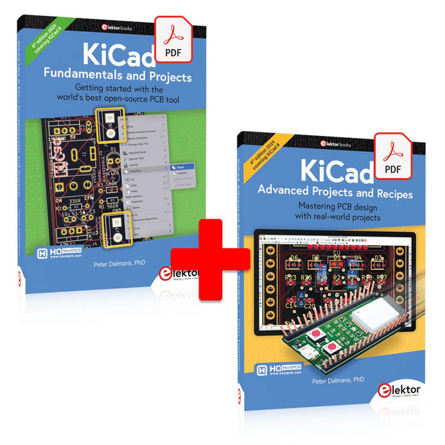
Elektor Digital KiCad Like A Pro (E-book Bundle)
This bundle includes both volumes of "KiCad Like a Pro" (4th edition 2024). In Fundamentals and Projects (normal price: €39.95), you'll learn how to use KiCad through a practical approach, helping you quickly become productive and start designing your own boards. Advanced Projects and Recipes (normal price: €34.95) allows you to practice your new KiCad skills by challenging yourself with a series of real-world projects. The latest iteration of KiCad, the world’s best free-to-use Printed Circuit Board tool, is packed with features usually found only in expensive commercial CAD tools. This modern, cross-platform application suite built around schematic and design editors, with auxiliary applications is a stable and mature PCB tool. KiCad 8 is a perfect fit for electronic engineers and makers. Here are the most significant improvements and features in KiCad 8, both over and under the hood: Modern user interface, completely redesigned from earlier versions Improved and customizable electrical and design rule checkers Theme editor allowing you to customize KiCad on your screen Ability to import projects from Eagle, CADSTART, and more Python scripting API Improved integrated SPICE circuit simulator Multi-sheet schematics Filters define selectable elements Enhanced interactive router helps you draw single tracks and differential pairs with precision New or enhanced tools to draw tracks, measure distances, tune track lengths, etc. Advanced interactive router Built-in bill of materials generator Realistic ray-tracing capable 3D viewer Customizable teardrops Plug-in manager for quick installation of themes, libraries and functionalities such as autorouters and BOM generators The first book KiCad Like A Pro – Fundamentals and Projects will teach you to use KiCad through a practical approach. It will help you become productive quickly and start designing your own boards. Example projects illustrate the basic features of KiCad, even if you have no prior knowledge of PCB design. The author describes the entire workflow from schematic entry to the intricacies of finalizing the files for PCB production and offers sound guidance on the process. The second book KiCad Like A Pro – Advanced Projects and Recipes will help you to practice your new KiCad skills by challenging you in a series of real-world projects. The projects are supported by a comprehensive set of recipes with detailed instructions on how to achieve a variety of simple and complex tasks. Design the PCBs for a solar power supply, an LED matrix array, an Arduino-powered datalogger, and a custom ESP32 board. Understand the finer details of the interactive router, how to manage KiCad project teams with Git, how to use an autorouter on 2 and 4-layer PCBs, and much more.
€ 84,95€ 69,95Best Price
-
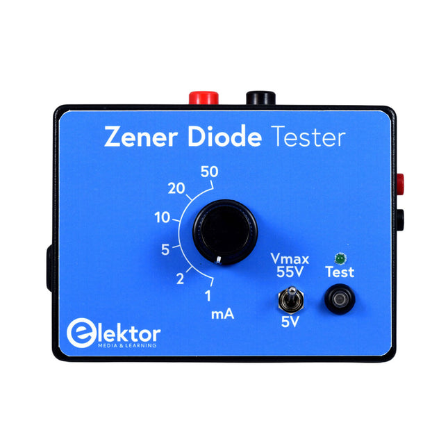
Elektor Zener Diode Tester
The Elektor Zener Diode Tester is essentially a constant-current source that can be switched in steps from 1 to 50 mA. It can be used to test Z-diodes up to a maximum of 54 V. Thanks to a 60-V step-up converter, the device can be powered by the usual 5 to 12 V. The principle of this tester is straightforward. A Z-diode or other DUT (device under test, such as an LED) is biased by an adjustable current source. The voltage across the DUT can be measured with a multimeter. The voltage of most (small) Z-diodes is specified at a current of 5 mA. Depending on the application, the voltage at other currents can also be of interest. That is why six current settings are available: 1, 2, 5, 10, 20, and 50 mA. LEDs are often specified at a current of 20 mA. What can be tested is: Whether a Z-diode is defective (short circuit or high impedance). Whether a Z-diode exhibits the correct Z-voltage. How a Z-voltage changes with different currents. What exact voltage is present at an integrated voltage reference. Whether LEDs in a series chain differ in brightness (hence the 20 mA current). What the current gain is for different base currents in (power) transistors. The kit contains all parts listed in the bill of materials including PCB and enclosure. Specifications Supply voltage 5…12 V/2 A (USB-C) Supply current (Itest = 50 mA) 1.1 A @ 5 V / 412 mA @ 12 V Selectable currents 1, 2, 5, 10, 20, and 50 mA Max. test voltage >54 V @ Itest ≥1 mA Max. output voltage 60 V @ Itest = 0 mA Voltage limit at 5 V 4.5 V @ Itest = 1 mA / 5.18 V @ Itest = 50 mA Enclosure dimensions 110 x 82 x 44 mm PCB size 105.4 x 67.3 mm Connections 4 mm banana sockets for multimeter 2 mm banana sockets for test clips USB-C socket for power supply Included Resistors R1 = 3.3 kΩ, 600 mW, 1% R2 = 0.15 Ω, 1 W, 5%, LS 12.7 mm, ø 3.5 mm R3, R8 = 180 Ω, 600 mW, 1% R4, R6, R16 = 1 kΩ, 600 mW, 1% R5, R19 = 47 kΩ, 600 mW, 1% R7 = 3.9 kΩ, 1 W, 5%, LS 12.7 mm, ø 3.5 mm R9, R10, R12 = 10 kΩ, 600 mW, 1% R11, R13 = 100 Ω, 600 mW 1% R14 = 249 Ω, 600 mW, 1% R15 = 499 Ω, 600 mW, 1% R17 = 2.49 kΩ, 250 mW, 1% R18 = 4.99 kΩ, 250 mW, 1% Capacitors C1 = 470 uF / 35 V, 20%, Ir = 1.86 A, ø 12.5 mm, LS 5 mm, ESR = 0.038 Ω (Panasonic EEUTP1V471) C2 = 1 uF / 100 V, 10%, X7R, LS 5 mm C3 = 2.2 nF / 50 V, 10%, X7R, LS 5 mm C4, C7 = 100 nF / 100 V, 10%, X7R, LS 5 mm C5 = 100 uF / 100 V, 20%, ø 14 mm max., LS 5 mm C6 = 1 nF / 100 V, 10%, X7R, LS 5 mm Inductor L1 = 100 uH, Irms = 2.4 A, Isat = 3.5 A, 0.09 Ω, radial, pitch 2.5/5/10 mm, ø 14 mm max. (Kemet SBC8-101-242) Semiconductors D1 = MUR120G, DO-41 D2, D4 = STPS3150RL, DO-201AD D3 = Z-diode, 18 V, 1.3 W (BZX85C18) D5 = Z-diode, 5.1 V, 0.5 W (1N5231B) LED1 = LED in pushbutton S1 LED2 = LED, green, 3 mm IC1 = MC34063, DIP-8 IC2 = LM4040BIZ-5.0/NOPB, TO-92 (TO-226AA-3) IC3 = TL051CP, DIP-8 T1 = BC327.25, TO-92 T2 = STP40NF10L, TO-220 T3 = IRF9510PBF, TO-220 T4 = 2N7000, TO-92 Others K1, K2, S1, S3 = 2-way screw terminal block, LS 3.5 mm, max. 1.5 mm² connected to K1 = USB-C socket, 30 V/3 A, chassis mounted, wired, 9 x 16 mm connected to K2 = Banana Connector, 2 mm, Socket, 60 VDC, Panel Mount, red (Multicomp 24.102.1) connected to K2 = Banana Connector, 2 mm, Socket, 60 VDC, Panel Mount, black (Multicomp 24.102.2) Test clip, red, 30 VAC/60 VDC (Hirschmann 931467101) Test clip, black, 30 VAC/60 VDC (Hirschmann 931467100) S1 = Pushbutton, panel mount, SPST-NO, 30 DC/100 mA, with red LED S2 = Rotary Switch, 6 position, 2 pole, 30°, 250 V/150 mA S3 = Toggle switch, panel mount, SPDT, solder lugs, 28 VDC T2, T3 = Heat sink, 15°C/W, FK 214 SA-CB Enclosure Hammond 1591XXSSBK, ABS, 110 x 82 x 44 mm Knob for S2, round shaft 6 mm, ø 21 mm, with indicator line (Multicomp CP-LB21-6-6D) 4 x Self-tapping screw #4-1/4", carbon steel, pan head Banana plug, red, 2 mm, 60 VDC (Multicomp 25.205.1) Banana plug, black, 2 mm, 60 VDC (Multicomp 25.205.2) Banana socket, black 4 mm, panel mount Banana socket, red 4 mm, panel mount for LED1, LED2 = Pin header, 1 x 2, vertical, pitch 2.54 mm for LED1, LED2 = Pin socket, 1 x 2, vertical, pitch 2.54 mm for T2, T3 = M3 screw, 10 mm, steel, pan head 2 x M3 washer, plain, steel 4 x M3 nut for IC1, IC3 = DIP-8 socket Wire, black, 0.25 mm² (24 AWG), stranded 14 x 0.15 mm, 1 m Wire, red, 0.25 mm² (24 AWG), stranded 14 x 0.15 mm, 1 m PCB 250772-1 v1.1 Links Article Elektor Labs
€ 99,95€ 79,95Best Price
-
Elektor Digital Universal Display Book for PIC Microcontrollers (E-book)
The newcomer to Microchip’s PIC microcontrollers invariably gets an LED to flash as their first attempt to master this technology. You can use just a simple LED indicator in order to show that your initial attempt is working, which will give you confidence to move forward. This is how the book begins — simple programs to flash LEDs, and eventually by stages to use other display indicators such as the 7-segment display, alphanumeric liquid crystal displays and eventually a colour graphic LCD. As the reader progresses through the book, bigger and upgraded PIC chips are introduced, with full circuit diagrams and source code, both in assembler and C. In addition, a small tutorial is included using the MPLAB programming environment, together with the EAGLE schematic and PCB design package to enable readers to create their own designs using the book’s many case studies as working examples to work from.
€ 19,95
Members: € 17,96
-
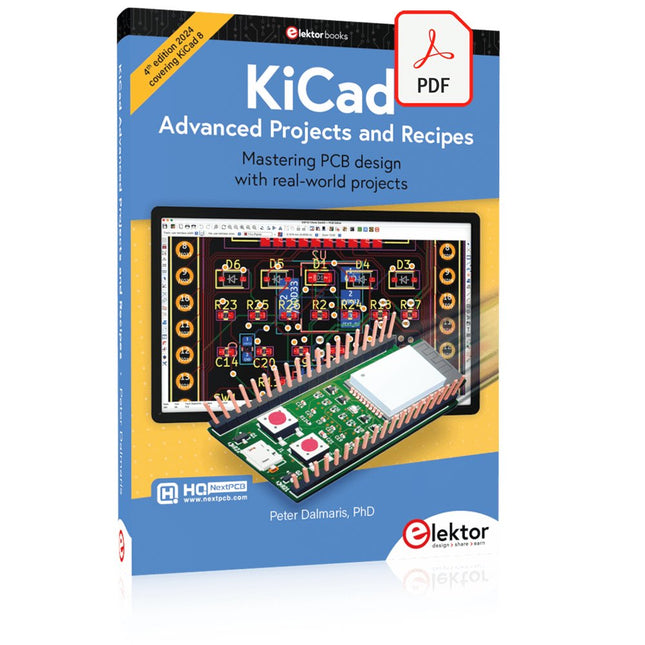
Elektor Digital KiCad Like A Pro – Advanced Projects and Recipes (E-book)
Mastering PCB design with real-world projects This book builts on KiCad Like a Pro – Fundamentals and Projects and aims to help you practice your new KiCad skills by challenging you in a series of real-world projects. The projects are supported by a comprehensive set of recipes with detailed instructions on how to achieve a variety of simple and complex tasks. Design the PCBs for a solar power supply, an LED matrix array, an Arduino-powered datalogger, and a custom ESP32 board. Understand the finer details of the interactive router, how to manage KiCad project teams with Git, how to use an autorouter on 2 and 4-layer PCBs, and much more. KiCad 8 is a modern, cross-platform application suite built around schematic and design editors. This stable and mature PCB tool is a perfect fit for electronic engineers and makers. With KiCad 8, you can create PCBs of any complexity and size without the constraints associated with the commercial packages. Here are the most significant improvements and features in KiCad 8, both over and under the hood: Modern user interface, completely redesigned from earlier versions Improved and customizable electrical and design rule checkers Theme editor allowing you to fully customize the look of KiCad on your screen Ability to import projects from Eagle, CADSTART, and more An improved and tightly integrated SPICE circuit simulator Autorouting with the Freerouting plugin Filters define which elements of a layout are selectable Enhanced interactive router helps you draw single tracks and differential pairs with precision New or enhanced tools to draw tracks, measure distances, tune track lengths, etc. Enhanced tool for creating filled zones A customizable coordinate system facilitates data exchange with other CAD applications Realistic ray-tracing capable 3D viewer Differential pair routing Rich repositories of symbol, footprint, and 3D shape libraries Python scripting API for programmatic customization and extensions Improved footprint wizard for fast custom footprints
€ 39,95
Members: € 35,96
-

Elektor Digital Professional SMD Assembly (E-book)
Practical Low-Cost Methods for Reliable PCB Production This book explains how to carry out reliable SMD assembly using affordable tools and small-scale equipment. It follows the complete workflow step by step, including tool selection, solder paste handling, stencil use, component placement, reflow methods, inspection, and rework. The focus is on bench-level and small-lab production rather than industrial assembly lines. It shows practical methods for building single and double-sided SMD boards with repeatable results. Topics include solder paste and flux, temperature profiles, hot air and hotplate techniques, small reflow ovens, inspection methods, and defect correction. Checklists and example workflows are included to help reduce errors and improve consistency. Key features: Tools and supplies for SMD assembly and rework Solder paste types, storage, and handling Stencils and paste application methods Pick and place workflow and component orientation Temperature profiles and reflow methods Hot air, hotplate, and reflow oven processes Inspection and quality control Common defects such as tombstoning and solder bridges Practical rework and component replacement Bench-level professional workflows and checklists This book is designed as a practical bench reference for anyone who wants to assemble and troubleshoot their own SMD boards with reliable results.
€ 19,95
Members: € 17,96
-
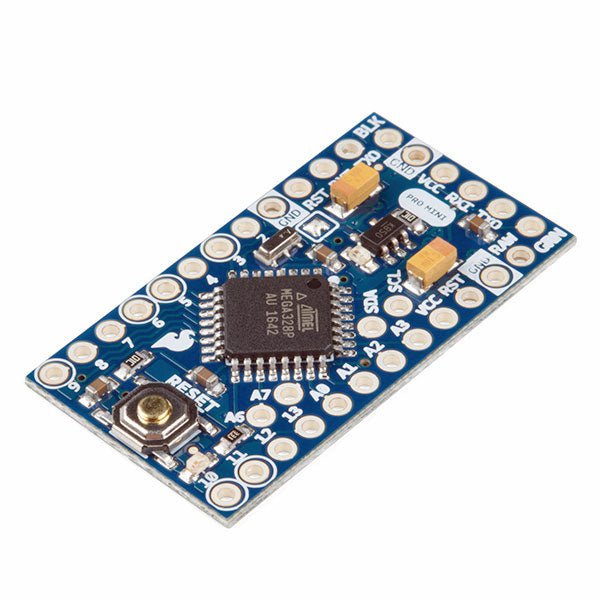
SparkFun SparkFun Arduino Pro Mini 328 (5 V, 16 MHz)
The Arduino Pro Mini is a microcontroller board based on the ATmega328P. It has 14 digital input/output pins (of which 6 can be used as PWM outputs), 6 analog inputs, an on-board resonator, a reset button, and holes for mounting pin headers. A six pin header can be connected to an FTDI cable or SparkFun breakout board to provide USB power and communication to the board. The Arduino Pro Mini is intended for semi-permanent installation in objects or exhibitions. The board comes without pre-mounted headers, allowing the use of various types of connectors or direct soldering of wires. The pin layout is compatible with the Arduino Mini. The Arduino Pro Mini was designed and is manufactured by SparkFun Electronics. Specifications Microcontroller ATmega328P Board Power Supply 5-12 V Circuit Operating Voltage 5 V Digital I/O Pins 14 PWM Pins 6 UART 1 SPI 1 I²C 1 Analog Input Pins 6 External Interrupts 2 DC Current per I/O Pin 40 mA Flash Memory 32 KB of which 2 KB used by bootloader SRAM 2 KB EEPROM 1 KB Clock Speed 16 MHz Dimensions 18 x 33.3 mm (0.7 x 1.3") Downloads Eagle files Schematics
€ 14,95€ 7,95Best Price


-
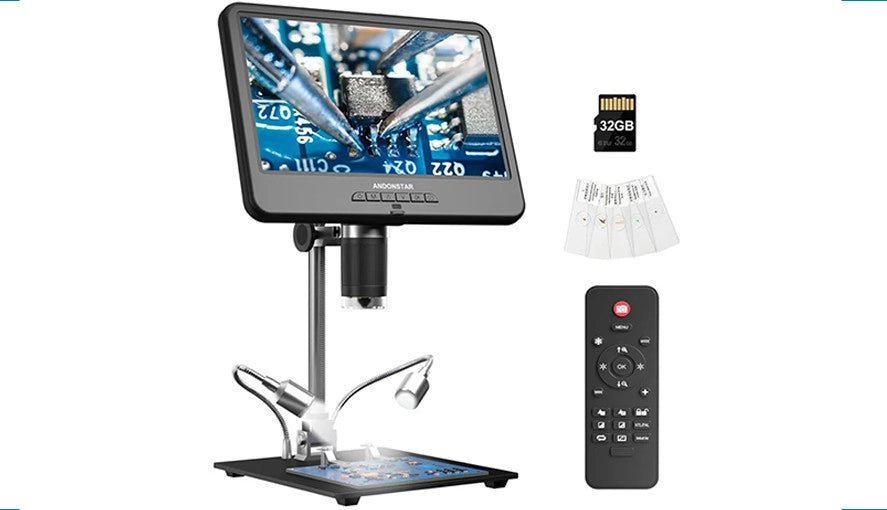
, by Clemens Valens Explore the Tiny World: Andonstar AD210 Digital Microscope in Focus
The Andonstar AD210 offers an accessible entry point into the world of digital microscopy with its expansive 10.1" display. Designed primarily for electronics labs, this...
-

, by Lobna Belarbi Kickstart Your Electronics Journey with Elektor’s Learning Collection
Whether you're new to electronics or aiming to level up your embedded skills, Elektor’s Learning Collection delivers expert-curated kits, courses, and hands-on bundles. The first...
