
Search results for "analog OR circuit OR design OR 3"
-

Elektor Digital Introduction to Electronic Filters (E-book)
Learn RC and RL Filters with Hands-On Circuits and Simulation Introduction to Electronic Filters is your comprehensive guide to understanding, designing, and applying first-order electronic filters using resistors, capacitors, and inductors. Whether you are a student, maker, or educator, this book demystifies the theory behind RC and RL filters and bridges the gap between concepts and real-world applications through simulation and experimentation. From the basics of frequency response and phase shift to hands-on breadboard builds and Python-based simulations, this book offers a deeply practical learning experience. You will learn to analyse filters using Bode plots and phasors, and explore applications in audio tone shaping, sensor signal conditioning, noise reduction, and power supply filtering. As you progress, you’ll build, measure, simulate, and tune filters using modern tools like CircuitLab, Python, and the Analog Discovery 3. Each chapter includes thoughtfully crafted activities that reinforce learning by doing – designing filters for specific tasks, simulating dynamic behaviour, and observing how theory translates into performance. Inside you’ll find: A clear introduction to the fundamentals of electronic filters Detailed explanations of RC and RL filters, cutoff frequency, and phase Guided activities using both simulation and hardware tools Real-life applications in audio, sensors, power supplies, and more A beginner-friendly primer on Python and algebra for electronics Whether you’re working through simulations or experimenting with real components on your workbench, this book will help you develop a solid understanding of electronic filters and their role in practical circuits.
€ 32,95
Members: € 29,66
-
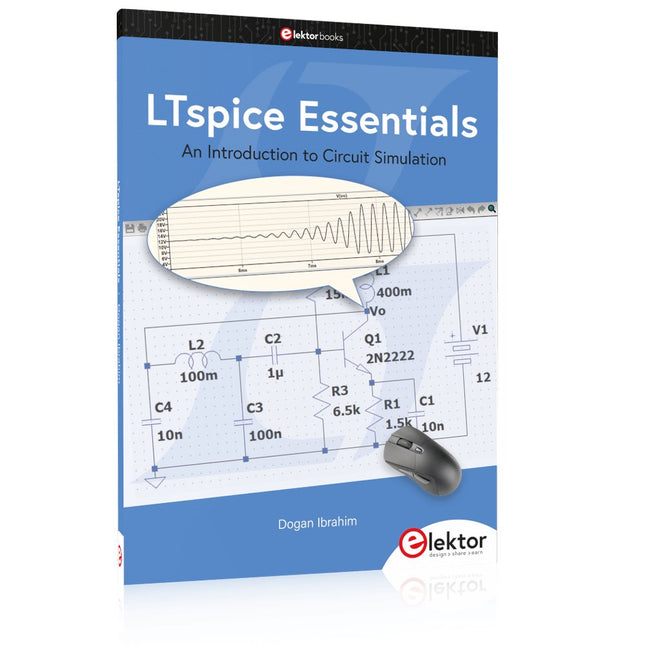
Elektor Publishing LTspice Essentials
An Introduction to Circuit Simulation LTspice, developed by Analog Devices, is a powerful, fast, and free SPICE simulator, schematic capture, and waveform viewer with a large database of components supported by SPICE models from all over the world. Drawing a schematic in LTspice is easy and fast. Thanks to its powerful graphing features, you can visualize the voltages and currents in a circuit, and also the power consumption of its components and much more. This book is about learning to design and simulate electronic circuits using LTspice. Among others, the following topics are treated: DC and AC circuits Signal diodes and Zener diodes Transistor circuits including oscillators Thyristor/SCR, diac, and triac circuits Operational amplifier circuits including oscillators The 555 timer IC Filters Voltage regulators Optocouplers Waveform generation Digital logic simulation including the 74HC family SPICE modeling LTspice is a powerful electronic circuit simulation tool with many features and possibilities. Covering them all in detail is not possible in a book of this size. Therefore, this book presents the most common topics like DC and AC circuit analysis, parameter sweeping, transfer functions, oscillators, graphing, etc. Although this book is an introduction to LTspice, it covers most topics of interest to people engaged in electronic circuit simulation. The book is aimed at electronic/electrical engineers, students, teachers, and hobbyists. Many tested simulation examples are given in the book. Readers do not need to have any computer programming skills, but it will help if they are familiar with basic electronic circuit design and operation principles. Readers who want to dive deeper can find many detailed tutorials, articles, videos, design files, and SPICE circuit models on the Internet. All the simulation examples used in the book are available as files at the webpage of this book. Readers can use these example circuits for learning or modify them for their own applications.
€ 39,95
Members: € 35,96
-

Elektor Publishing Introduction to Electronic Filters
Learn RC and RL Filters with Hands-On Circuits and Simulation Introduction to Electronic Filters is your comprehensive guide to understanding, designing, and applying first-order electronic filters using resistors, capacitors, and inductors. Whether you are a student, maker, or educator, this book demystifies the theory behind RC and RL filters and bridges the gap between concepts and real-world applications through simulation and experimentation. From the basics of frequency response and phase shift to hands-on breadboard builds and Python-based simulations, this book offers a deeply practical learning experience. You will learn to analyse filters using Bode plots and phasors, and explore applications in audio tone shaping, sensor signal conditioning, noise reduction, and power supply filtering. As you progress, you’ll build, measure, simulate, and tune filters using modern tools like CircuitLab, Python, and the Analog Discovery 3. Each chapter includes thoughtfully crafted activities that reinforce learning by doing – designing filters for specific tasks, simulating dynamic behaviour, and observing how theory translates into performance. Inside you’ll find: A clear introduction to the fundamentals of electronic filters Detailed explanations of RC and RL filters, cutoff frequency, and phase Guided activities using both simulation and hardware tools Real-life applications in audio, sensors, power supplies, and more A beginner-friendly primer on Python and algebra for electronics Whether you’re working through simulations or experimenting with real components on your workbench, this book will help you develop a solid understanding of electronic filters and their role in practical circuits.
€ 39,95
Members: € 35,96
-
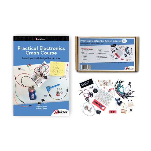
Elektor Bundles Practical Electronics Crash Course (Bundle)
Getting started in electronics is not as difficult as you may think. With this bundle (book + kit of parts), you can explore and learn the most important electrical and electronics engineering concepts in a fun way by doing various experiments. You will learn electronics practically without getting into complex technical jargon and long calculations. As a result, you will be creating your own projects soon. This kit contains the components required to build most of the detailed examples of the book on a breadboard and try them out for real. The kit can, of course, also be used without the book for building other circuits and doing your own experiments. Kit contents 1x 39 Ω, 1 W resistor 1x 47 Ω resistor 1x 180 Ω resistor 1x 330 Ω resistor 3x 1 kΩ resistor 1x 2.2 kΩ resistor 1x 3.9 kΩ resistor 1x 6.8 kΩ resistor 1x 10 kΩ resistor 1x 15 kΩ resistor 1x 22 kΩ resistor 1x 33 kΩ resistor 1x 47 kΩ resistor 1x 56 kΩ resistor 1x 82 kΩ resistor 1x 120 kΩ resistor 1x 680 kΩ resistor 2x 100 kΩ resistor 1x 10 kΩ trimmer 1x 10 kΩ linear potentiometer 1x 100 kΩ linear potentiometer 1x LDR 1x 1 nF ceramic capacitor 2x 10 nF ceramic capacitor 1x 100 nF ceramic capacitor 1x 1 µF, 25 V aluminium electrolytic capacitor 2x 10 µF, 25 V aluminium electrolytic capacitor 1x 100 µF, 25 V aluminium electrolytic capacitor 1x 470 µF, 25 V aluminium electrolytic capacitor 1x 1000 µF, 25 V aluminium electrolytic capacitor 1x RGB LED, Common-Cathode (CC) 1x 1N4148 small signal diode 1x 1N4733A 5.1 V, 1 W Zener diode 3x LED, red 2x BC337 NPN transistor 1x IRFZ44N N-channel MOSFET 2x NE555 timer 1x LM393 comparator 1x 74HCT08 quad AND gate 3x Tactile switch 2x SPDT switch 1x Relay, SPDT, 9 VDC 1x Active buzzer 1x Passive buzzer 50 cm Solid wire, 16 AWG, unjacketed 2x PP3 9 V battery clip 1x Breadboard 20x Jumper wire This bundle contains: Practical Electronics Crash Course Kit (valued at: €45) Book: Practical Electronics Crash Course (normal price: €45)
€ 89,95€ 69,95Best Price
-
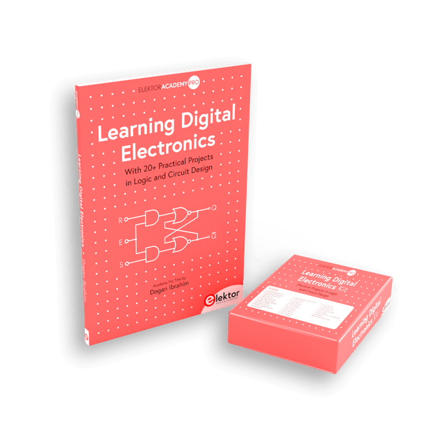
Elektor Bundles Learning Digital Electronics (Bundle)
Master digital electronics – the hands-on way! This bundle includes the book Learning Digital Electronics, featuring 20+ practical projects in Logic and Circuit design, as well as a 100-piece kit – so you can start building logic circuits, counters, displays, and more right away. Learning Digital Electronics (Book) This book is a practical guide to digital electronics, covering the essential components of modern digital systems: number systems, logic gates, Boolean algebra, combinational and sequential logic, and more. Through more than 20 structured projects, you’ll design and build digital systems using real-world components such as logic gates, multiplexers, decoders, flip-flops, counters, and shift registers. The projects range from basic LED logic circuits to digital locks, display systems, traffic light controllers, and timing-based designs. Selected projects introduce the use of tools such as CircuitVerse for circuit simulation, while several designs make use of 74HC-series logic devices, commonly used in digital hardware prototyping. Inside, you’ll find: Clear coverage of number systems and binary arithmetic Logic gate fundamentals and universal gate implementations Step-by-step projects using flip-flops, counters, and registers Real-world design with 74HC-series logic chips Techniques for designing combinational and sequential systems This book takes a design-first, application-driven approach to digital electronics—built around working circuits, tested logic, and hands-on experimentation. Learning Digital Electronics (Kit) This kit has been specially developed to complement the book "Learning Digital Electronics". Since all necessary components are included, you can complete every practical project in the book directly. Kit contents 2x 74HC08 AND gate chip 2x 74HC00 NAND gate chip 1x 74HC86 XOR gate chip 1x 555 timer chip 1x 74HC161 counter chip 1x 74HC164 shift register 1x CD4511 7-segment decoder 1x CD4027 JK flip-flop 1x BC337 NPN transistor 1x KPS-5161 7-segment common-cathode display 1x Light dependent resistor (LDR) 4x 10 KΩ resistors 8x 1 KΩ resistor 2x 47 KΩ resistors 1x 100 KΩ resistor 4x 2.7 KΩ resistors 1x 5.6 KΩ resistor 1x 150 KΩ resistor 1x 10 μF capacitor 2x 0.01 μF capacitor 2x 100 nF capacitor 8x Small red LED 1x Small green LED 1x Small orange LED 4x Pushbutton switches 1x Active buzzer 1x Battery holder for 3x AA batteries (batteries not included) 1x Breadboard 40x Male-to-male jumper wires (length: 200 mm)
€ 69,95€ 59,95Best Price
-
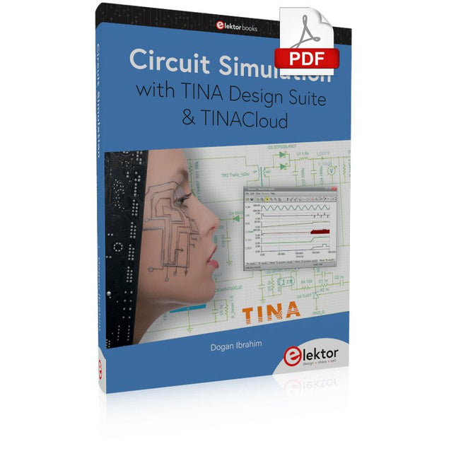
Elektor Digital Circuit Simulation with TINA Design Suite & TINACloud (E-book)
TINA Design Suite is a professional, powerful and affordable circuit simulator. It is a circuit designer and PCB design software package for analysing, designing, and real-time testing of analogue, digital, IBIS, VHDL, Verilog, Verilog AMS, SystemC, MCU, and mixed electronic circuits and their PCB layouts. In this book, top-selling Elektor author, Prof. Dr. Dogan Ibrahim aims to teach the design and analysis of electrical and electronic circuits and develop PCB boards using both TINA and TINACloud. The book is aimed at electrical/electronic engineers, undergraduate electronic/electrical engineering students at technical colleges and universities, postgraduate and research students, teachers, and hobbyists. Many tested and working simulation examples are provided covering most fields of analogue and digital electrical/electronic engineering. These include AC and DC circuits, diodes, zener diodes, transistor circuits, operational amplifiers, ladder diagrams, 3-phase circuits, mutual inductance, rectifier circuits, oscillators, active and passive filter circuits, digital logic, VHDL, MCUs, switch-mode power supplies, PCB design, Fourier series, and spectrum. Readers do not need to have any programming experience unless they wish to simulate complex MCU circuits.
€ 39,95
Members: € 35,96
-

FNIRSI FNIRSI 2D15P (3-in-1) 2-ch Oscilloscope (100 MHz) + Multimeter + Signal Generator
The FNIRSI 2D15P is a compact 3-in-1 test tool combining a 2-channel digital oscilloscope, True RMS multimeter, and waveform generator in one device. With a 4.3" capacitive touchscreen, 100 MHz bandwidth, 500 MSa/s sampling rate, and up to 1,200 fps capture speed, it’s ideal for fast troubleshooting, signal analysis, and electronics testing. Features Dual-Channel Input (100 MHz single-channel, 50 MHz dual-channel operation) Selectable Memory Depths 20 MHz Bandwidth Limit Grayscale & Color Temperature Visualization Math Operations (Add, Subtract, Multiply, Divide, etc.) XY Mode & Infinite Persistence Cursor Function & 13 Auto Measurements Auto / Normal / Single Trigger Modes True RMS Multimeter (19,999 Counts) 10 MHz DDS Signal Generator Specifications General Display 4.3" IPS Capacitive Touchscreen Operation Touch + Knob + Physical Buttons Charging USB-C (12 V/1 A fast charging) Battery 5000 mAh Lithium battery Dimensions 19.6 x 12.9 x 5.7 cm Weight 1.1 kg Oscilloscope Channels 2 Analog Bandwidth 100 MHz Sample Rate 500 MSa/s Memory Depth 10K, 100K, 1M Input Impedance 1 MΩ Timebase Range 5ns - 50s Vertical Sensitivity 10 mV - 10 V/div Max Input Voltage 800 V (x10 Probe) Trigger Mode Auto, Normal, Single Trigger Type Rising, Falling, Both Edges Coupling AC/DC Persistence min / 2s / 5s / 10s / 20s / 50s / ∞ Math Operations Yes Waveform Capture Yes Waveform Export Yes Cursor Measurement Yes Multimeter DC Voltage 1.9999V / 19.999V / 199.99V / 1000V AC Voltage 1.9999V / 19.999V / 199.99V / 750.0V DC Current 19.999mA / 199.99mA / 1.9999A / 9.999A AC Current 19.999mA / 199.99mA / 1.9999A / 9.999A Resistance 19.999MΩ / 1.9999MΩ / 199.99KΩ / 19.999KΩ / 1.9999KΩ / 199.99Ω Capacitance 999.9uF / 99.99uF / 9.999uF / 999.9nF / 99.99nF / 9.999nF / 9.999mF / 99.99mF Diode Yes Continuity Yes Signal Generator Channels 1 Frequency 0–10 MHz Amplitude 0.1–3.0 Vpp Duty Cycle 0–100% Included 1x FNIRSI 2D15P Oscilloscope 2x P6100 Oscilloscope Probes 1x Multimeter Probe 1x Alligator Clip Probe 1x USB Data Cable 1x Manual Downloads Manual Firmware V2.7.0.7
€ 209,00€ 179,95Best Price
-

Red Pitaya Red Pitaya STEMlab 125-14 PRO Gen 2 Starter Kit (incl. Book)
This bundle includes the Red Pitaya STEMlab 125-14 PRO Gen 2 Starter Kit and the new book "Experimenting with Red Pitaya STEMlab Gen 2". The Red Pitaya STEMlab 125-14 PRO Gen 2 Starter Kit is a powerful and flexible platform for signal processing, data acquisition, and electronic measurement applications. Designed for engineers, developers, researchers, and educators, this kit provides everything required to start building advanced measurement and control systems. At the core of the kit is the STEMlab 125-14 PRO Gen 2 board, an upgraded and ultra-lightweight development platform. Powered by the Xilinx Zynq-7010 SoC with 512 MB of RAM, it combines FPGA programmability with ARM processing power to enable high-performance instrumentation and custom signal-processing solutions. The board offers 14-bit ADC and DAC resolution, a 125 MS/s sampling rate, an input range of ±20 V, and up to 60 MHz bandwidth. Its improved low-noise analog front-end, USB-C connectivity, and compact design make it suitable for demanding applications such as RF development, radar systems, photonics research, software-defined radio (SDR), and industrial automation. The Starter Kit includes all essential accessories for immediate use: a microSD card with preinstalled operating system, power supply, Ethernet cable for remote access, two 100 MHz oscilloscope probes, and SMA-to-BNC adapters for flexible signal connections. The Red Pitaya STEMlab 125-14 PRO Gen 2 Starter Kit is an excellent platform for rapid prototyping, FPGA development, measurement instrumentation, and advanced electronics experimentation. Features 14-bit ADC and DAC resolution 125 MS/s sampling rate ±20 V input range Up to 60 MHz bandwidth Xilinx Zynq-7010 SoC (FPGA + ARM processor) 512 MB RAM Low-noise analog front- and back-ends Applications RF development and testing Radar and wireless systems Software-defined radio (SDR) Photonics and optical research Industrial automation and control systems Signal analysis and instrumentation Rapid prototyping of electronic measurement systems Specifications Processor Dual-core ARM Cortex-A9 FPGA AMD Xilinx Zynq-7010 SoC RAM 512 MB (4 Gb) Storage microSD card (up to 32 GB) Operating System Linux-based Red Pitaya OS ADC Resolution 14-bit DAC Resolution 14-bit Bandwidth 60 MHz (DC) Sampling Rate 125 MS/s Analog Input Channels 2 Analog Output Channels 2 Input Voltage Range ±1 V (LV) / ±20 V (HV) Input Impedance 1 MΩ / 10 pF Output Voltage Range ±1 V Ethernet 1x Gigabit Ethernet (RJ45) USB 2x USB-C 2.0 (for power and console) Digital I/O 16x GPIO (3.3 V) Communication Interfaces I²C, SPI, UART, CAN Power Supply 5 V/3 A via USB-C Dimensions 106.8 x 60.0 x 17.9 mm Included 1x Red Pitaya STEMlab 125-14 PRO Gen 2 board 2x 100 MHz oscilloscope probes 2x SMA-to-BNC adapters 1x microSD card with preinstalled OS 1x USB-C Power supply 1x Ethernet cable Downloads Documentation Schematics Book: Experimenting with Red Pitaya STEMlab Gen 2 With this new book, Red Pitaya goes beyond a versatile board. It becomes a powerful laboratory instrument for precision measurement, analysis, and control. From the fundamentals of electronic project development, monitoring, control, and design to testing, this book walks you step-by-step through everything you need to know to harness the full potential of Red Pitaya hardware and software. The book presents real-time, FPGA-based projects that are developed on a PC using the Vivado environment, then transferred to the Red Pitaya for execution and testing. You will learn about enhanced performance, expanded I/O capabilities, improved FPGA features, and advanced connectivity options that open up new frontiers for precision measurement, monitoring, and control in your embedded applications. Inside the book you will discover: A deep dive into Red Pitaya architecture and hardware design Electronic experiments using Red Pitaya for measurement and monitoring Hands-on projects using the Python programming language Practical guidance for FPGA programming using Red Pitaya Red Pitaya FPGA projects using the Verilog HDL under Vivado IDE Practical design of electronic projects including measurement and testing Step-by-step examples that bridge theory and real-world implementation Whether you are designing your own electronic circuits, developing signal analysis tools, or creating real-time control or monitoring systems, this book provides you the knowledge and confidence you need to fully learn and customize the Red Pitaya platform.
€ 799,00
Best Price
-

Elektor Bundles 555-Timer-Projekte (Bundle)
Dieses Bundle befasst sich mit der Entwicklung von Projekten, die auf dem 555-Timer-IC basieren. Das Buch enthält über 45 vollständig getestete und dokumentierte Projekte. Zusammen mit dem Kit, das mehr als 130 durchkontaktierte Bauteile enthält, können Sie alle beschriebenen Projekte auf einem Breadboard nachbauen. Der Aufbau macht es auch einfach, die Projekte zu modifizieren und mit ihnen zu experimentieren. Über 45 Projekte für den legendären 555-Chip (und den 556, 568) Einige der Projekte im Buch sind: Abwechselnd blinkende LEDs Veränderung der Blinkrate von LEDs Touchsensor-Ein/Aus-Schalter Ein-/Ausschaltverzögerung Lichtabhängiger Ton Dunkel-Hell-Lichtschalter Tonburst-Generator Langzeit-Timer Lauflichter LED-Roulette-Spiel Ampelsteuerung Durchgangsprüfer Elektronisches Schloss Kontaktentprellung für Schalter Spielzeug-Elektronikorgel Mehrfachsensor-Alarmsystem Metronom Spannungsmultiplizierer Elektronischer Würfel 7-Segment-Display-Zähler Motorsteuerung 7-Segment-Display-Würfel Elektronische Sirene Verschiedene andere Projekte Inhalt des Kits Widerstände 1x 15 kΩ 1x 68 kΩ 2x 47 kΩ 1x 82 kΩ 2x 820 Ω 1x 8,2 kΩ 3x 10 kΩ 1x 1,8 kΩ 1x 6,8 kΩ 14x 2,2 kΩ 10x 680 Ω 1x 27 kΩ 1x 5,6 kΩ 1x 560 kΩ 1x 4,7 kΩ 1x 3,3 kΩ 3x 33 kΩ 1x 36 kΩ 2x 100 kΩ 5x 1 kΩ 1x 3,9 kΩ 2x 56 kΩ 2x 12 kΩ 1x 10 kΩ Potentiometer 1x 1 MΩ Potentiometer 2x 50 kΩ Potentiometer 3x 20 kΩ Potentiometer 1x 10 kΩ Potentiometer 1x 10 kΩ Potentiometer 1x 50 kΩ Potentiometer 1x 100 kΩ Potentiometer 1x 50 kΩ Potentiometer Kondensatoren 1x 0,33 μF 1x 1 μF 1x 10 nF 1x 22 nF 1x 47 nF 1x 100 nF 1x 10 μF electrolytisch 1x 33 μF electrolytisch 2x 100 μF electrolytisch LEDs 10x 5 mm rote LED 10x 3 mm rote LED 3x 3 mm gelbe LED 3x 3 mm grüne LED 1x 7-Segment-LED mit gemeinsamer Kathode Halbleiter 3x 555-Timer 1x CD4017 Counter 1x CD4026 Counter 1x CD4011 NAND-Gate 4x 1N4148 Diode 1x IRFZ46N MOSFET 1x Thermistor 1x Lichtabhängiger Widerstand (LDR) Sonstiges 1x Passiver Summer 1x Aktiver Summer 1x SG90-Servo 1x 8 Ω Mini-Lautsprecher 1x 9 V DC Bürstenmotor 1x 5 V Relais 1x 9 V Batterieclip 7x Drucktastenschalter 1x Breadboard 1x Breadboard-Überbrückungskabel
€ 69,95€ 54,95Best Price
-
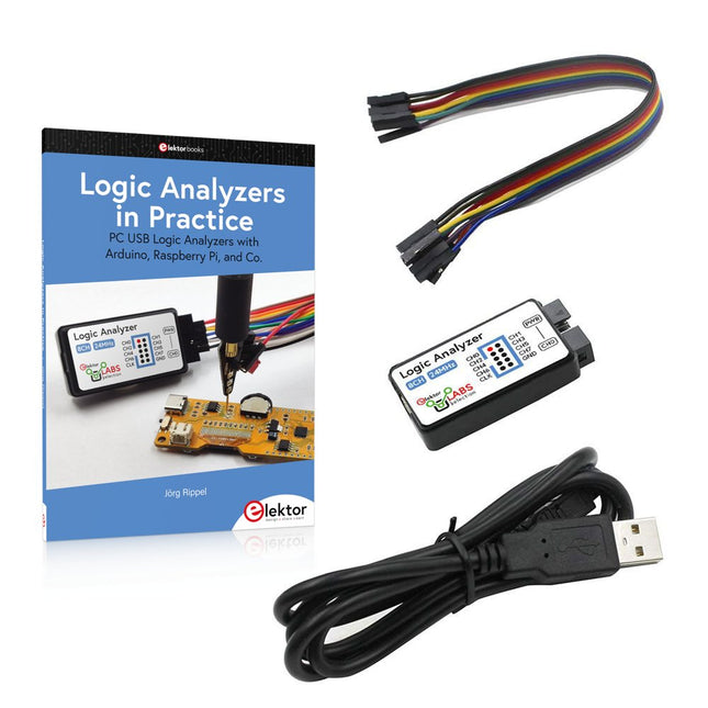
Elektor Bundles Logic Analyzers in Practice (Bundle)
Book: Logic Analyzers in Practice Step-by-step instructions guide you through the analysis of modern protocols such as I²C, SPI, UART, RS-232, NeoPixel, WS28xx, HD44780 and 1-Wire. With the help of numerous experimental circuits based on the Raspberry Pi Pico, Arduino Uno and the Bus Pirate, you will learn the practical application of popular USB logic analyzers. All the experimental circuits presented in this book have been fully tested and are fully functional. The necessary program listings are included – no special programming or electronics knowledge is required for these circuits. The programming languages used are MicroPython and C along with the development environments Thonny and Arduino IDE. This book uses several models of flexible and widely available USB logic analyzers and shows the strengths and weaknesses of each price range. You will learn about the criteria that matter for your work and be able to find the right device for you. Whether Arduino, Raspberry Pi or Raspberry Pi Pico, the example circuits shown allow you to get started quickly with protocol analysis and can also serve as a basis for your own experiments. After reading this book, you will be familiar with all the important terms and contexts, conduct your own experiments, analyze protocols independently, culminating in a comprehensive knowledge set of digital signals and protocols. USB Logic Analyzer (8-ch, 24 MHz) This USB Logic Analyzer is an 8-channel logic analyzer with each input dual purposed for analog data recording. It is perfect for debugging and analyzing signals like I²C, UART, SPI, CAN and 1-Wire. It operates by sampling a digital input connected to a device under test (DUT) at a high sample rate. The connection to the PC is via USB. Specifications Channels 8 digital channels Maximum sampling rate 24 MHz Maximum input voltage 0 V ~ 5 V Operating temperature 0°C ~ 70°C Input impedance 1 MΩ || 10 pF Supported protocols I²C, SPI, UART, CAN, 1-Wire, etc. PC connection USB Dimensions 55 x 28 x 14 mm Downloads Software This bundle contains: Book 'Logic Analyzers in Practice' (normal price: €35) USB Logic Analyzer (8-ch, 24 MHz) (normal price: €20) USB Cable Jumper Wire Ribbon Cable
€ 54,95€ 44,95Best Price


-
, by Udo Bormann Electronics Projects Archive for Engineers, Makers & Education
Access thousands of electronics projects, Arduino tutorials, audio designs, and power supply circuits with Elektor Classics USB sticks. Designed for younger engineers, university professors, electronics educators,...
-
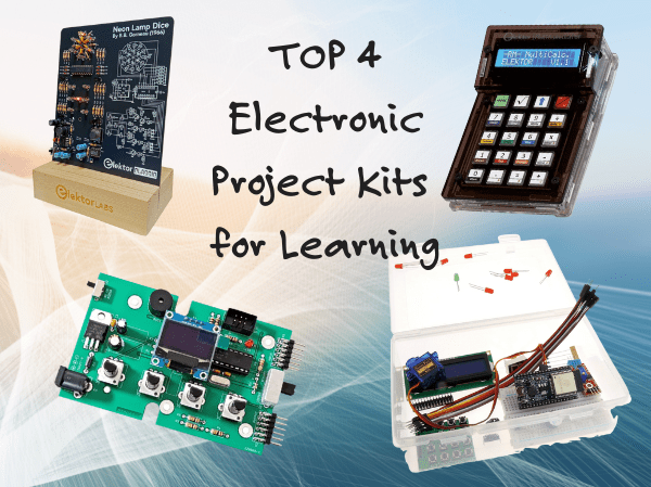
, by Udo Bormann Top 4 Elektor Electronics Project Kits for Learning and Skill Development
Discover four of Elektor’s most exciting electronics kits — from IoT and Arduino to retro logic and motion control. Whether you're just starting out or...
