
Search results for "seeed OR studio OR grove OR gps OR module"
-
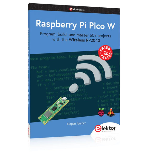
Elektor Publishing Raspberry Pi Pico W (Book)
Program, build, and master 60+ projects with the Wireless RP2040 The Raspberry Pi Pico and Pico W are based on the fast, efficient, and low-cost dual-core ARM Cortex M0+ RP2040 microcontroller chip running at up to 133 MHz and sporting 264 KB of SRAM and 2 MB of Flash memory. Besides spacious memory, the Pico and Pico W offer many GPIO pins, and popular peripheral interface modules like ADC, SPI, I²C, UART, PWM, timing modules, a hardware debug interface, and an internal temperature sensor. The Raspberry Pi Pico W additionally includes an on-board Infineon CYW43439 Bluetooth and Wi-Fi chipset. At the time of writing this book, the Bluetooth firmware was not yet available. Wi-Fi is however fully supported at 2.4 GHz using the 802.11b/g/n protocols. This book is an introduction to using the Raspberry Pi Pico W in conjunction with the MicroPython programming language. The Thonny development environment (IDE) is used in all of the 60+ working and tested projects covering the following topics: Installing the MicroPython on Raspberry Pi Pico using a Raspberry Pi or a PC Timer interrupts and external interrupts Analogue-to-digital converter (ADC) projects Using the internal temperature sensor and external sensor chips Using the internal temperature sensor and external temperature sensor chips Datalogging projects PWM, UART, I²C, and SPI projects Using Bluetooth, WiFi, and apps to communicate with smartphones Digital-to-analogue converter (DAC) projects All projects are tried & tested. They can be implemented on both the Raspberry Pi Pico and Raspberry Pi Pico W, although the Wi-Fi-based subjects will run on the Pico W only. Basic programming and electronics experience are required to follow the projects. Brief descriptions, block diagrams, detailed circuit diagrams, and full MicroPython program listings are given for all projects.
€ 44,95
Best Price
-

Elektor Digital Édition spéciale : Shields pour Arduino (PDF)
Concrétisez vos rêves, réalisez les projets les plus fous : un odomètre pour la roue de votre hamster, la surveillance complètement automatisée de votre fourmilière avec interface web, ou le Sandwich-O-Mat ? une machine qui grille les sandwichs de votre choix. Avec les cartes Arduino et le mouvement DIY (« fais-le toi-même ») ou maker, se mettre à programmer des microcontrôleurs est devenu un jeu d?enfant. Une deuxième révolution a eu lieu : des développeurs ingénieux ont mis sur le marché de petites cartes ? appelées « shields » ou modules ? qui simplifient considérablement l?utilisation d?autres dispositifs. Ces petits modules contiennent tous les composants électroniques nécessaires pour la connexion au microcontrôleur ; quelques fils avec des fiches suffisent pour le raccordement, ce qui évite d?avoir à câbler et fait gagner du temps. En outre, il est également possible de manipuler de minuscules composants dépourvus de pattes de connexion (ceux de type CMS). Projets Arduino et le monde extérieur Capteur BMP180, introduction aux bibliothèques et à l?I²C Initiation aux entrées/sorties avec un shield polyvalent Adaptateur I²C pour LCD et afficheurs à matrice de points Shield clavier & LCD Convertisseur de niveau W5100 : connexion à internet Shields d?extension des entrées/sorties Relais et relais statiques Shield multifonction : unité de commande universelle Connexion d?un lecteur de carte SD par SPI Touches et afficheurs à 7 segments Convertisseur analogique/numérique à 16 bits Convertisseur numérique/analogique MCP4725 Pilote de servomoteurs à 16 voies PWM Lecteur MP3 Enregistreur de données GPS avec stockage sur carte SD Capteur tactile Joystick SHT31 : température et humidité Capteur d?UV-A VEML6070 Temps de vol VL53L0X Mesure de distance à ultrasons Afficheur matriciel à LED à base de MAX7219 Horloge en temps réel DS3231 Circuit d?extension de port MCP23017 Communication radio à 433 MHz Gyroscope MPU-6050 Accéléromètre ADXL345 LED RVB WS2812 Cartes d?alimentation Capteurs de gaz MQ-xx Capteur de dioxyde de carbone (CO2) Capteur de courant ACS712 Capteur de courant INA219 Pilote de moteur L298 Kit RFID MFRC522 Moteur pas à pas 28BYJ-48 Carte avec pilote de moteur ultra-silencieux TMC2209 Potentiomètre numérique X9C10x Écran couleur TFT avec contrôleur/pilote ST7735 Écran à encre électronique Module Bluetooth Compteur Geiger Module GSM SIM800L Multiplexeur I²C Module CAN (Controller Area Network)
€ 10,95
Members: € 9,86
-

Elektor Digital SPS-Programmierung mit dem Raspberry Pi und dem OpenPLC-Projekt (PDF)
Einführung in die SPS-Programmierung mit dem Open-Source-Projekt auf dem Raspberry Pi und Modbus-Beispiele mit dem Arduino Uno und ESP8266 Die SPS-Programmierung ist heute in der Industrie und in der Hausautomation sehr weit verbreitet. In diesem Buch beschreibt der Autor, wie der Raspberry Pi 4 als SPS eingesetzt werden kann. Angefangen mit der Softwareinstallation auf dem Raspberry Pi und dem SPS-Editor auf dem PC geht es nach einer Beschreibung der Hardware an das Programmieren. Es folgen interessante Beispiele nach IEC 61131-3 in den verschiedenen Programmiersprachen. Ausführlich wird auch erklärt, wie der SPS-Editor benutzt wird und wie die Programme auf den Raspberry Pi geladen und ausgeführt werden. Angefangen mit der Programmierung mit KOP (Kontaktplan) über ST (Structured Control Language) bis zu AS (Special Function Chart) werden alle IEC-Sprachen mit Beispielen behandelt. Diese können auf der Website des Autors heruntergeladen werden. Auch die Vernetzung kommt nicht zu kurz. Der Arduino Uno und der ESP8266 werden als ModbusRTU- bzw. ModbusTCP-Module programmiert, um Zugriff auf externe Peripherie zu erhalten. Damit ist es möglich, Sensoren einzulesen und Verbraucher zu schalten. Interessant dürften auch E/A-Schaltungen sein, die dem 24V-Industriestandard entsprechen. Befehlsübersichten für ST und KOP runden das Buch ab. Nach dem Durcharbeiten des Buches ist der Leser in der Lage, eigene SPS-Steuerungen mit dem Raspberry Pi zu verwirklichen.
€ 32,80
Members: € 29,52
-

Elektor Labs Elektor Low-Noise Lab Power Supply
The Elektor Low-Noise Lab Power Supply is a fully analogue, adjustable, medium-power symmetrical bench supply that contains no switching or digital components. It provides an output voltage adjustable between 0 V and ±22 V, and an output current adjustable from 0 A to 1 A. Because it avoids any form of switching circuitry, the design delivers extremely low noise. To display both output voltages and currents, four miniature moving-coil panel meters are used. Most modern laboratory power supplies and AC adapters employ switch-mode techniques. Even the best examples inevitably exhibit high-frequency ripple and other switching artefacts on their output, which can interfere with the testing of sensitive analogue circuits and disturb low-level measurements. To overcome this, the concept here is a completely analogue power supply. Although less efficient than its switch-mode counterparts, the reduced efficiency is of little importance for test-bench use and ensures cleaner, more reliable measurement results. Because many analogue circuits require a symmetrical supply, this design delivers positive and negative output voltages of equal magnitude. A small amount of adjustment is available to compensate for any imbalance. Naturally, a variable current-limit function is also included. The kit includes the components required to build the power supply, except for the transformers. Specifications Output Voltage 0…+22 V, 0, −22 V Output Current 0…+1 A, 0…−1 A Noise −85 dBV, (at 0.95 A/20 V, B = 22 kHz) −84 dBV (at 0.95 A/20 V, B > 500 kHz) Ripple 50 µVRMS (at 950 mA/20 V, B = 22 kHz, mainly 100 Hz component) Included 3x PCBs: Regulator (PCB-1), Mains Filter (PCB-2) and Transformer (PCB-3) All the components except the AC transformers 4x moving-coil meters Additional parts for wiring (wires, banana sockets, IEC Power entry module, etc.) Not included The three AC transformers An enclosure Parts List For the Regulator PCB (240386-1) Resistors (250 mW, 1%) R1 = 12 Ω R2, R8, R37, R62 = 1 MΩ R3, R7, R10, R13, R17, R20, R22, R30, R35, R42, R45, R47, R55, R60 = 100 Ω, 600 mW R4, R5 = 4.7 kΩ R6 = 100 kΩ R9, R12, R14, R36, R38, R39, R61, R63, R66, R72, R78, R79 = 10.0 kΩ, 600 mW R11 = 9.76 kΩ, 600 mW R15, R40 = 44.2 kΩ, 600 mW R16, R41, R77 = 1 kΩ R18, R43 = 1.5 kΩ, 1 W, 5% R19, R44 = 470 Ω, 1 W, 5% R21, R46 = 330 Ω, 600 mW R23, R24, R48, R49 = 1.0 Ω, 1 W R25, R50 = 1 kΩ, 1 W, 5% R26, R28, R51, R53 = 1.000 kΩ 0.1%, 15 ppm/C R27, R29, R52, R54 = 10.00 kΩ 0.1%, 15 ppm/C R31, R56 = 1.2 kΩ, 1 W, 5% R32, R57 = 47 kΩ R33, R58 = 270 Ω R34, R59 = 27 kΩ R64, R69 = 12.0 kΩ R65 = 3.0 kΩ, 600 mW R67, R80 = 470 Ω, 600 mW R68, R70 = 6.8 kΩ, 600 mW R71 = 30.0 kΩ,, 600 mW R73, R74, R75, R76 = 10 MΩ P1, P2, P3 = 10 kΩ, 200 mW, 20%, potentiometer, 1 turns, single, lin., panel mount P4, P5 = 500 Ω, 500 mW, 10%, trimmer, 25 turns, 3296Y-1-501LF Bourns P6, P7 = 10 kΩ, 500 mW, 10%, trimmer, 25 turns, 3296Y-1-501LF Bourns Capacitors C1 = 100 nF, 50 V, 10%, ceramic X7R, LS 5 mm C2, C3, C6, C7, C30 = 10 µF, 63V, 20%, LS 2.5 mm, 3000hours@105°C C4, C5, C8, C9, C13, C14, C18, C19, C23, C24, C28, C29, C31, C32, C38, C39 = 100 nF, 250 V, 10%, PET, LS 7.5 mm C10, C20 = 47 nF, 100 V, 5%, PET, LS 5 mm C11, C21 = 10 nF, 100 V, 5%, PET, LS 5 mm C12, C22 = 220 µF, 35 V, 20%, 0.024 Ω, LS2.5/3.5 mm, Ir 3.4 A, 2000hours@125°C, polymer C15, C25 = 120 µF, 50 V, 20%, ESR 0.02 Ω, Diam. 10 mm max., LS 5 mm C16, C26 = 15 nF, 100 V, 5%, PET, LS 5 mm C17, C27 = 47 nF, 100 V, 5%, PET, LS 5 mm C33, C34 = 22 µF, 50 V, 20%, LS 2 mm, 10000 hours @ 105°C C35, C36, C44, C45 = 1 µF, 100 V, 10%, LS 5 mm, ceramic X7R C37 = 100 uF, 50 V, 20%. LS 3.5 mm C40, C41, C42, C43, C46, C47, C48, C49 = 1000 µF, 50 V, 20%, LS 5/7.5 mm, Ir 3.32 A, 10000hours@105°C, D 16 mm C50, C51, C52, C53 = 47 nF, 100 V, 10%, ceramic X7R, LS 5 mm Inductors L1, L2 = 4.7 µH, 3.2 A, 0.033 Ω, LS 5 mm, RLB0914-4R7ML Bourns L3 = Commom mode choke, 14.5 mH, 3 A, SSRH24NH-30145 Kemet Semiconductors D1, D2, D3, D4, D5, D9, D10, D11, D15 = BAT85, DO-34 D6, D7, D12, D13 = SR560, DO-201AD D8, D14, D16 = 1N4148, DO-35 D17 = Zenerdiode, 5.6 V, 0.5 W, DO-41 D18, D19 = 1N4004, DO-41 D20, D21 D22, D23 = V30100CI-M3/P, dual common cathode, TO-220 D24 = Zener diode, 30 V, 1 W, DO-41 LED1, LED2 = LED, red, T-1 (3 mm) LED3, LED4 = LED, green, T-1 (3 mm) TVS1, TVS2 = BZW50-33B, R6 T1, T2, T4 = BC337.25, TO-92 T3 = NJW0302G, TO-3P T5, T6, T8 = BC327.25, TO-92 T7 = NJW0281G, TO-3P T9 = BD139, TO-126 (SOT-32) IC1 = LM334Z, TO-92 IC2 = LM4040AIZ-5.0/NOPB, TO-92 (TO-226AA-3) IC3, IC4 = OPA2992IDR, SOIC-8 IC5, IC6 = OPA4992IDR, SOIC-14 IC7 = OPA992IDBVR, SOT-23-5 IC8 = LM339N, DIP-14 IC9 = LM317, TO-220 IC10 = LM337, TO-220 Others F1, F2 = 5×20 mm fuse, 1.6 A, fast acting HS1, HS2 = Heatsink MC33271 (for T3/T7), 2.7°C/W, PCB mount, height 63.5 mm K1, K4 = 3-way screw terminal block, LS 3.5 mm, max. 1.5 mm² K2, K3 = 3-way screw terminal block, LS 3.5 mm, max. 1 mm² M1, M3 = Moving coil meter, Range 30 V, type 91C4, 45×45 mm M2, M4 = Moving coil meter, Range 1 A, type 91C4, 45×45 mm² RE1 = Relay DPDT,5V, UA2-5NU Miscellaneous 3× 3-way screw terminal block, LS 3.5 mm, max. 1 mm² (for P1, P2, P3) 4× Pin header, 1×2, vertical, pitch 2.54 mm (for LED1, LED2, LED3, LED4) 4× Pin socket, 1×2, vertical. pitch 2.54 mm (for LED1, LED2, LED3, LED4) 2× Heatsink FK222SA220, 20°C/W, PCB mount (for IC9 & IC10) 2× Mica thermal pad for TO-220, 12×18×0.05 mm (for IC9 & IC10) 2× Insulating bushing IB 6, TO-220 (for IC9 & IC10) 2× Ceramic thermal pad, 23×20×2 mm (for T3 & T7) 2× PCB Fuse Holder, for 5×20 mm fuse, 10 A (for F1, F2) 2× Cover for PCB Fuse Holder, transparent (for F1, F2) 2× 2-way screw terminal block, LS 3.5 mm, max. 1 mm² (for M1 & M3) 2× 2-way screw terminal block, LS 3.5 mm, max. 1.5 mm² (for M2 & M4) 8× M3 solder lug, thickness 0.35 mm (for M1…M4) M4 solder lug, thickness 0.35 mm (to connect 4 mm banana connectors) Screened cable, 1 pair, 2×24 AWG/0.22 mm², 1 m (for P1, P2 & P3) IC socket, DIP, 14 contacts (for IC8) M3 washer, plain, steel M3 screw, 16 mm, steel, pan head M3 nut M3 spring washer 50 mm M3 standoff, steel, male-female 12 mm M3 standoff, steel, male-female 10 mm M3 standoff, steel, male-female M3 screw, 8 mm, steel, pan head For the Mains Fiter PCB (240386-2) Resistor R1 = 220 kΩ, 1 W, 500 V, 5% Capacitors C1, C2 = 470 nF, 305 VAC, Class X2, 11 × 27 mm max., LS 15/22.5 mm C3, C4, C5, C6 = 2.2 nF, 300 VAC, Class Y2, 13 × 4 mm, LS 10 mm, PP Inductors L1, L2 = Common-mode choke, 6.8 mH, 1.7 A, TDK B82732R2172B030 Semiconductor MOV1 = TVS varistor, 300 VAC, S14K300 (230 VAC, B72214S0301K101) and SK14K150 (150 VAC, B72214S0151K101) Others K1, K2 = 3-way screw terminal block, LS 7.62 mm F1 = Time-delay fuse, 0.5 A (230 VAC) or 1 A (115 VAC) Miscellaneous 1× Fuse holder, 5×20 mm, 10 A, 500 VAC 1× Transparent fuse cover 4× 10 mm M3 standoff, steel, male–female 4× M3 screw, 8 mm, steel, pan head 4× M3 nut For the Transformer PCB (240386-3) Resistors R1, R2 = 2.7 kΩ, 600 mW, 1% R3 = 10.0 kΩ, 600 mW, 1% Capacitor C1 = 220 µF, 50 V, 20%, Ø10 mm, LS 5 mm, 4000 h @ 105°C Transformers (not included in this kit!) TR1, TR2, TR3 = 2×7 V, 25 VA, PCB-mounted toroid, 70060K Talema Semiconductors D1–D4 = 1N4148, DO-35 D5, D6 = 1N4004, DO-41 D7 = Zener 5.6 V, 1.3 W, DO-41 LED1 = LED, red, T-1 (3 mm) IC1, IC2 = MOC8021M, CTR ≥ 1000%, DIP-6 Others F1, F2, F3 = 160 mA time-delay fuse (230 VAC) or 315 mA time-delay fuse (115 VAC) K1 = 2-way screw terminal block, LS 7.62 mm K2 = 3-way screw terminal block, LS 3.5 mm, max 1.5 mm² K3, K4 = 3-way screw terminal block, LS 3.5 mm, max 1 mm² RE1, RE2 = Relay DPDT, 5 A/250 VAC / 24 VDC Miscellaneaous 1× Pin header 1×2, pitch 2.54 mm + matching socket for LED1 3× Fuse holder 5 × 20 mm, 10 A, 500 VAC + transparent cover 3× M4 screw, 8 mm, pan head + washer for TR1-TR3 8× M3 screw, 8 mm, pan head + nut + washer 8× 10 mm M3 standoff, steel, male–female 2× IC socket, DIP-6 for IC1 & IC2 Additional Parts 1 m red insulated wire, stranded, 1.5 mm² 0.5 m blue insulated wire, stranded, 1.5 mm² 0.5 m black insulated wire, stranded, 1.5 mm², 0.5 m 2 m red insulated wire, stranded, D 0.56 mm (0.25 mm²) 2 m black insulated wire, stranded, D 0.56 mm (0.25 mm²) 0.5 m Multicore Cable, Flexible, 3 Core, 0.75 mm² (24 x 0.2 mm) Red banana socket Black banana socket Blue banana socket Green banana socket IEC Power Entry Module with switch, IEC C14 3 crimp terminals, FASTON, 4.75 x 0.81 mm 3 knobs Links Elektor Labs JumpStarter Page Article (Part 1) Article (Part 2)
€ 249,00
Best Price
-

Elektor September/Oktober 2025 (NL)
Elektor GREEN en GOLD leden kunnen deze uitgave hier downloaden. Nog geen lid? Klik hier om een lidmaatschap af te sluiten. ESP32 Audio Transceiver Board (Deel 2)Draadloze audio-overdracht Inductieve AM-zenderGebruikt Pico's PIO in een Arduino-sketch Navigeren door draadloze protocollen navigerenEen technische gids Satelliettracking met behulp van LoRaHet TinyGS-netwerk brengt gegevens uit de ruimte naar de aarde. 4G-Compatibele SMS afstandsbedieningBedien je apparatuur op afstand Hogesnelheids-probeIngangen met hoge impedantie voor signalen tot 200 MHz Uit het leven gegrepenKafka KrakenSDR Prestatietests met de RP2350Is een upgrade van Raspberry Pi Pico 1 naar versie 2 de moeite waard? Contactloze E-veldmetingen (2)Een laservibrometer voor het beoordelen van de trillingen van het membraan Kristallen en oscillatorenVerbetering van de kristalnauwkeurigheid door gerichte keuze van condensatoren Alle begin......gaat audio! Zelf firmware coderen voor embedded projecten SPECTRAN® V6 MobileModulaire, configureerbare realtime-spectrumanalyzer voor betrouwbare metingen over alle frequentiebereiken De toekomst van AI wordt gesmeed in siliciumEen interview met Anastasiia Nosova Autonome Sensor-Node v2.0 (Systeemarchitectuur)Zonne-energieplatform met geïntegreerde GPS, LoRaWAN en meer Precieze positioneringBluetooth channel sounding getest Testgestuurd ontwikkelen bij het schrijven van firmware Telefoon gestuurde modelautoWi-Fi + ESP32 + Smartphone = Afstandsbediening 2025: Een AI-odysseeAI-redeneermodellen: De gedachtegang-revolutie Zonne-laadregelaar met MPP-tracking (3)Software en Inbedrijfstelling Raspberry Pi Zero Web Streaming CameraDe ZeroTier VPN gebruiken Beste soldeerder van de Beneluxvakmanschap in de schijnwerpers Seminaroverzicht Electronics & ApplicationsLeer, ontdek en netwerk op E&A 2025 Eurocircuits at E&A 2025 E&A gadget 2025: racen over de beursvloer met slimme printplaat op wielenVijf vragen aan Casper van Doorne, ontwerper van de beursgadget Beursgadget E&A bekendontwerp en bestuur je eigen raceauto Vakbeurs E&A is het elektronicaparadijs van de Benelux“Techneuten blijven kinderen” Rohde & SchwarzPioneering Innovation in Test & Measurement Diederik Jekel opent Electronics & Applications
€ 15,95
-

Elektor Digital Elektor Septembre/Octobre 2025 (PDF) FR
Le téléchargement intégral de ce numéro est disponible pour nos membres GOLD et GREEN sur le site Elektor Magazine ! Pas encore membre ? Cliquez ici. carte émetteur-récepteur audio ESP32 (2)Transmission audio sans fil émetteur AM par inductionUtiliser les PIO du Pico dans un croquis Arduino les protocoles sans filUn guide technique suivi de satellites avec LoRaTinyGS, le réseau open source qui capte les données spatiales télécommande par sms compatible 4GContrôlez votre équipement à distance sonde haute vitesseMesure à haute impédance jusqu’à 200 MHz sur le vifKafka KrakenSDR tests de performance avec le RP2350Pico 2 : une vraie amélioration ? mesures de champ électrique sans contact (2)Un vibromètre laser pour l’analyse des vibrations de la membrane quartz et oscillateursAméliorer la précision des quartz grâce au choix des condensateurs démarrer en électroniqueCI audio originaux se lancer dans le codage d'un projet DIY SPECTRAN® V6 MobileAnalyseur de spectre temps réel modulaire et configurable pour des mesures fiables sur l’ensemble des plages de fréquences l’avenir de l’IA repose sur le siliciumEntretien avec Anastasiia Nosova nœud de capteurs autonome v2.0 (architecture du système)Plateforme de mesure autonome alimentée par énergie solaire, avec GPS intégré, LoRaWAN et plus encore positionnement précisTests du sondage de canal Bluetooth développement logiciel piloté par les tests voiture miniature contrôlée par SmartphoneWi-Fi + ESP32 + Smartphone = contrôle à distance 2025 : une odyssée de l’IAModèles de raisonnement en IA : la révolution de la chaîne de pensée contrôleur de charge solaire avec MPPT (3)Logiciel et mise en service caméra Web Raspberry Pi ZeroStreaming avec VPN ZeroTier
€ 10,95
-
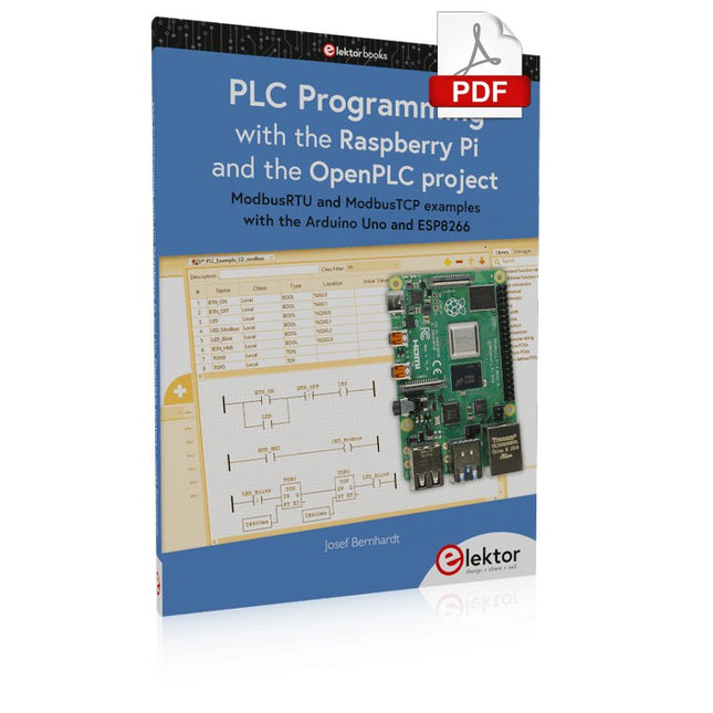
Elektor Digital PLC Programming with the Raspberry Pi and the OpenPLC Project (E-book)
ModbusRTU and ModbusTCP examples with the Arduino Uno and ESP8266 Introduction to PLC programming with OpenPLC, the first fully open source Programmable Logic Controller on the Raspberry Pi, and Modbus examples with Arduino Uno and ESP8266 PLC programming is very common in industry and home automation. This book describes how the Raspberry Pi 4 can be used as a Programmable Logic Controller. Before taking you into the programming, the author starts with the software installation on the Raspberry Pi and the PLC editor on the PC, followed by a description of the hardware. You'll then find interesting examples in the different programming languages complying with the IEC 61131-3 standard. This manual also explains in detail how to use the PLC editor and how to load and execute the programs on the Raspberry Pi. All IEC languages are explained with examples, starting with LD (Ladder Diagram) over ST (Structured Control Language) to SFC (Special Function Chart). All examples can be downloaded from the author's website. Networking gets thorough attention too. The Arduino Uno and the ESP8266 are programmed as ModbusRTU or ModbusTCP modules to get access to external peripherals, reading sensors and switching electrical loads. I/O circuits complying with the 24 V industry standard may also be of interest for the reader. The book ends with an overview of commands for ST and LD. After reading the book, the reader will be able to create his own controllers with the Raspberry Pi.
€ 32,95
Members: € 29,66
-
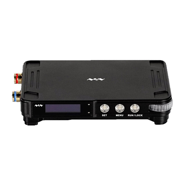
Miniware Miniware MDP-P906 Digital Power Supply (300 W)
MDP-P906 has a built-in cooling fan, and maximum output power of up to 300 W, which meets a wider range of testing needs and application scenarios. Through 2.4 GHz wireless communication, it can be connected to MDP-M01 Smart Digital Monitor module to realize the free combination of multiple channels of 300 W per channel. MDP-P906 has the index, stability and reliability comparable to a professional power supply. It can output pure current, and provide powerful functions such as programmable output, timing output, timing control, automatic compensation, boost mode, etc., making itself a real cost-effective, smart and customized programmable linear DC power supply. MDP-P906 adopts a precision CNC machined aluminum alloy shell, with fine workmanship, novel, mini and beautiful appearance, it completely subverts the rigid image of traditional desktop power supply. With stackable modular design and wireless communication function, MDP-P906 can work independently or paired, both on the workbench, and be carried out for on-site maintenance. MDP-P906 is a perfect solution for electronic engineer, especially field application engineers to meet different needs of power sources. Built-in silent cooling fan, instant cooling, ensure a stable and efficient output! Smart linear compensation, constant voltage & constant current Positive & negative output, series boost, parallel current sharing Applications Universal tests and teaching experiments in R&D laboratory Maintenance of digital products Property verification and fault diagnosis of devices and circuits Emergency power supply for model airplanes and vehicles Power supply testing of RF and microwave circuits or modules Quality control and quality inspection Supply purified power for high-accuracy digital-analog hybrid circuits and Hi-Fi audio devices Specifications Input DC 4.2-30 V/14 A (Max)QC 3.0/PD2.0, 20 V/5 A (Max) Output 0-30 V/0-10 A, 300 W (Max) Conversion efficiency 95% Output resolution 10 mV/2 mA, up to 1 mV/1 mA via Display Control module Output accuracy 0.03%+5 mV0.05%+2 mV Adjustment rate Load adjustment rate <±0.01%Power adjustment rate <±0.01% Ripple and noise <250 uVrms, 3 mVpp; 2 mArms Transient response <4 uS Safety protections Input over-voltage, under-voltage, reverse connection protection, output over-current, back-flow protection and over-temperature protection Others Automatically shut-down and enter micro-power modeSupport USB firmware upgrade Dimensions 112 x 66 x 20 mm Weight 181 g Included 1x MDP-P906 Digital Power Supply 2x Output Cable 1x User Manual Downloads User Manual v1.1 Firmware v1.32
€ 171,95
-

Elektor Special: Sensoren für Wetter und Umwelt
Bauen Sie Ihre perfekte Wetterstation oder forschen Sie zusammen mit der ganzen Welt an Umweltdaten. Mit vielen praktischen Projekten für Arduino, Raspberry Pi, NodeMCU, ESP32 und weiteren Developmentboards. Wetterstationen erfreuen sich seit Jahrzehnten großer Beliebtheit. Ob in aktuellen oder längst eingestellten Elektronik-Magazinen – regelmäßig finden sich Beiträge zum Eigenbau einer Wetterstation. Im Laufe der Jahre wurden diese Systeme immer ausgefeilter und können heute nahtlos in das Smart Home integriert werden. Allerdings erfordert dies oft die Bindung an einen (teuren) Markenhersteller, der sämtliche Komponenten abdeckt. Mit Ihrer eigenen Wetterstation können Sie jedoch mühelos mithalten – und sogar Messwerte erfassen, die kommerzielle Geräte nicht bieten. Dabei kommt der Spaß nicht zu kurz: Sie erweitern spielerisch Ihr Wissen über Elektronik, moderne Mikrocontroller-Developmentboards und Programmiersprachen. Schon für weniger als zehn Euro können Sie erste Umweltdaten erfassen und Ihr System Schritt für Schritt mit wachsendem Interesse weiter ausbauen. Aus dem Inhalt: Wind und Wetter auf der Spur Wetterdisplay mit OpenWeatherMap und Vakuum-Fluoreszenzanzeige Flüchtige organische Verbindungen in der Atemluft Mit MQ-Sensoren arbeiten: Kohlenmonoxid messen – geruchlos aber extrem giftig CO2-Ampel mit ThingSpeak-IoT-Anbindung Ein Gießautomat für Ihre Pflanzen Gutes Raumklima: Temperatur und Luftfeuchtigkeit sind wichtige Kriterien Schickes Thermometer mit alter Röhrentechnik Nostalgisches Wetterhäuschen für die ganze Familie Luftdruck und Temperatur genau messen Sonnenbrand-Warngerät DIY-Sensor für die Sonnenscheindauer Das Smartphone zeigt’s an: Nebel oder klare Sicht? Erdbeben erkennen Pegelstände von Gewässern und Behältern pH-Wert von Gewässern bestimmen Radioaktive Strahlung erkennen Mit GPS wissen Sie weltweit, wo ihr Sensor ist Logdateien mit Zeitstempel auf SD-Karten speichern LoRaWAN, The Things Network und ThingSpeak LoRaWAN-Gateway für TTN betreiben Mega-Display mit Wettervorhersage
€ 14,90
Members: € 13,41
-

Elektor Digital Explore ATtiny Microcontrollers using C and Assembly Language (E-book)
AVR Architecture and Programming An in-depth look at the 8-bit AVR architecture found in ATtiny and ATmega microcontrollers, mainly from a software and programming point of view. Explore the AVR architecture using C and assembly language in Microchip Studio (formerly Atmel Studio) with ATtiny microcontrollers. Learn the details of how AVR microcontrollers work internally, including the internal registers and memory map of ATtiny devices. Program ATtiny microcontrollers using an Atmel-ICE programmer/debugger, or use a cheap hobby programmer, or even an Arduino Uno as a programmer. Most code examples can be run using the Microchip Studio AVR simulator. Learn to write programs for ATtiny microcontrollers in assembly language. See how assembly language is converted to machine code instructions by the assembler program. Find out how programs written in the C programming language end up as assembly language and finally as machine code instructions. Use the Microchip Studio debugger in combination with a hardware USB programmer/debugger to test assembly and C language programs, or use the Microchip Studio AVR simulator. DIP packaged ATtiny microcontrollers are used in this volume for easy use on electronic breadboards, targeting mainly the ATtiny13(A) and ATtiny25/45/85. Learn about instruction timing and clocks in AVR microcontrollers using ATtiny devices. Be on your way to becoming an AVR expert with advanced debugging and programming skills.
€ 34,95
Members: € 31,46
-
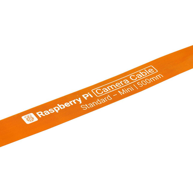
Raspberry Pi Foundation FPC Camera Cable for Raspberry Pi 5 (500 mm)
Raspberry Pi 5 provides two four-lane MIPI connectors, each of which can support either a camera or a display. These connectors use the same 22-way, 0.5 mm-pitch “mini” FPC format as the Compute Module Development Kit, and require adapter cables to connect to the 15-way, 1 mm-pitch “standard” format connectors on current Raspbery Pi camera and display products.These mini-to-standard adapter cables for cameras and displays (note that a camera cable should not be used with a display, and vice versa) are available in 200 mm, 300 mm and 500 mm lengths.
€ 3,95€ 1,95Best Price
-

Elektor September/Oktober 2026 (NL)
Elektor GREEN en GOLD leden kunnen deze uitgave hier downloaden. Nog geen lid? Klik hier om een lidmaatschap af te sluiten. De ESP-BLASTEen mini ESP32 raketdrone die ruim 100 km/u vliegt STM32Cube Innovation-ChallengeDoe mee met je beste STM32C5-ontwerp Wireless workshop (1)Radiomodules uitgelegd: 433 MHz CC1101 sub-GHz-transceiver AM-zenderMet sinus- en blokgolfgenerator op Raspberry Pi Pico AudiotronicaDe vervormingsfactor CoffeeCallerOmroepsysteem met mesh-netwerk en Zephyr gebaseerde software Elektor wordt 65Projecten uit voorgaande september- en oktobermaanden Bluetooth Channel Sounding voor het volgen van objectenAfstandsmeting met centimeterprecisie voor het IoT van de volgende generatie 2026: Een AI-odysseeKwantumcomputing is geen volgende GPU Om de cloud te beveiligen, is edge-beveiliging nodig Eerste ervaringen met de HackRF ProPraktische tests met de nieuwe SDR-hardware Modemupgrade van GPRS/2G naar LTE/4GEen draadloos alarmsysteem als voorbeeld Lusvormige antenne met RF-bouwstenenDeel 1: Een zelfbouw kortegolfantenne met instelbare richtingsgevoeligheid Internetradio naar AM-converterMet een ESP32-S3 als zender Err-lectronics Mioty, een overzichtFraunhofer's aanpak van LPWAN WerkbankwijsheidPraktische tips van experts Walter, de compacte IoT-moduleDeel 2: Toegang tot weer- en datadiensten
€ 15,95


