
Search results for "rtl OR sdr OR software OR defined OR radio OR with OR dipole OR antenna OR kit"
-
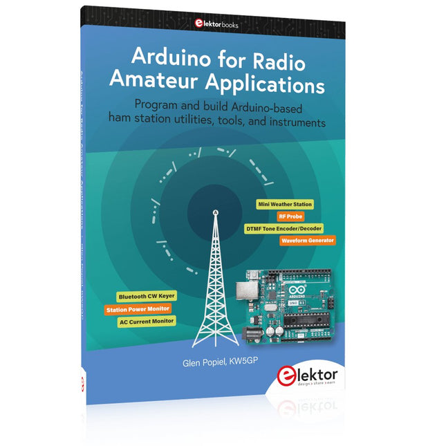
Elektor Publishing Arduino for Radio Amateur Applications
Program and build Arduino-based ham station utilities, tools, and instruments In addition to a detailed introduction to the exciting world of the Arduino microcontroller and its many variants, this book introduces you to the shields, modules, and components you can connect to the Arduino. Many of these components are discussed in detail and used in the projects included in this book to help you understand how these components can be incorporated into your own Arduino projects. Emphasis has been placed on designing and creating a wide range of amateur radio-related projects that can easily be built in just a few days. This book is written for ham radio operators and Arduino enthusiasts of all skill levels, and includes discussions about the tools, construction methods, and troubleshooting techniques used in creating amateur radio-related Arduino projects. The book teaches you how to create feature-rich Arduino-based projects, with the goal of helping you to advance beyond this book, and design and build your own ham radio Arduino projects. In addition, this book describes in detail the design, construction, programming, and operation of the following projects: CW Beacon and Foxhunt Keyer Mini Weather Station RF Probe with LED Bar Graph DTMF Tone Encoder DTMF Tone Decoder Waveform Generator Auto Power On/Off Bluetooth CW Keyer Station Power Monitor AC Current Monitor This book assumes a basic knowledge of electronics and circuit construction. Basic knowledge of how to program the Arduino using its IDE will also be beneficial.
€ 39,95
Members: € 35,96
-

Elektor Digital Elektor 09-10/2026 (PDF) DE
Diese Ausgabe steht allen GOLD- und GREEN-Mitgliedern auf der ElektorMagazine-Website zum Download bereit! Sie sind noch kein Mitglied? Hier klicken! Der ESP-BLASTEine Mini-Raketendrohne mit ESP32, die über 100 km/h erreicht Wireless Workshop (1)Freigeschaltetes Funkmodul: 433-MHz-CC1101-Sub-GHz-Transceiver AM-Sendermit Rechteck-/Sinuswellengenerator auf Raspberry Pi Pico STM32Cube Innovations ChallengeTreten Sie mit Ihrem besten STM32C5-Design an CoffeeCallerWie ein langer Flur zu einer maßgefertigten Mesh-Netzwerk-Platine führte AudiotronicsKlirrfaktor Elektor ist 65Projekte aus früheren September/Oktober-Ausgaben Geräteortung durch Bluetooth Channel SoundingZentimetergenaue Entfernungsmessung im IoT der nächsten Generation 2026: Eine KI-OdysseeQuantencomputing ist nicht die nächste GPU Cloud-Schutz durch Edge-Sicherheit Erste Erfahrungen mit dem HackRF ProPraktische Tests mit der neuen SDR-Hardware Herausforderung ElektromobilitätEffiziente Lötlösungen für moderne Fahrzeugtechnik Modem-Update von GPRS/2G auf LTE/4Gam Beispiel einer Funk-Alarmzentrale Loop-Antenne mit RF BricksTeil 1: Kurzwellen-Antenne mit einstellbarer Richtwirkung im Selbstbau Internetradio-zu-AM-KonverterVerwendung eines ESP32-S3 als Sender Projekt 2.0 mioty – ein ÜberblickLPWAN à la Fraunhofer Werkbank-WeisheitPraktische Tipps von Experten Walter, das kompakte IoT-ModulTeil 2: Zugriff auf Wetter- und Datendienste
€ 11,90
-
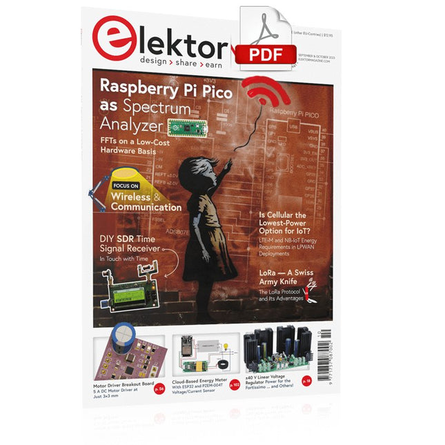
Elektor Digital Elektor September/October 2023 (PDF)
Elektor GREEN and GOLD members can download their digital edition here. Not a member yet? Click here. Raspberry Pi Pico as Spectrum AnalyzerFFTs on a Low-Cost Hardware Basis ±40-V Linear Voltage RegulatorAn Alternative Power Supply for the Fortissimo-100 Power Amplifier… and Others! MCU Wireless Communication Made FlexibleEEPROM Opens Networking Prospects for Wireless MCUs €5,000 up for grabs!Join the STM32 Wireless Innovation Design Contest 2023: An AI OdysseyGetting Started with ChatGPT’s Code Interpreter LoRa, a Swiss Army Knife (1)The LoRa Protocol and Its Advantages Adjustable Current Sink with Integrated Clock GeneratorTest Power Supplies, Voltage Converters and Batteries Two New Arduino UNO R4 Boards: Minima and WiFi Logarithmic PotentiometersThey’re Exponential! Motor Driver Breakout BoardA BoB for a 5 A DC Motor Driver with a 3×3 mm Size From Life’s ExperienceHazardous Electronics Is Cellular the Lowest-Power Option for IoT?LTE-M and NB-IoT Energy Requirements in LPWAN Deployments Wireless Communication in IoT Systems – Using Arduino MKR ModulesThe Right Board for Wi-Fi, LoRa, and Many More Standards AC Losses in Magnetic ComponentsAvoid Hot Inductors! Measurement for Optimal Cloud Deployment Matter Adoption: What does it take to deploy Matter devices? YARD Stick OneA Sub-1 GHz Wireless Test Tool Latching RelaysPeculiar Parts, the Series PIC O’Clock – In Touch with TimeDesigning an SDR Time Signal Receiver Due Diligence DirectiveBusiness as Usual Will Not Do Starting Out in Electronics……Voltage Amplification Infrasound Recorder with the Arduino Pro MiniA Sample Project from Elektor’s “Arduino & Co.” Book Cloud-Based Energy MeterWith ESP32 Module and PZEM-004T Voltage/Current Sensor A Bare-Metal Programming Guide (Part 2)Accurate Timing, the UART, and Debugging Hexadoku
€ 7,50
-
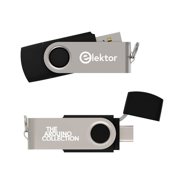
Elektor Classics The Elektor Arduino Collection (USB Stick)
This USB Stick contains more than 300 Arduino-related articles published in Elektor Magazine. The content includes both background articles and projects on the following topics: Software & hardware development: Tutorials on Arduino software development using Arduino IDE, Atmel Studio, Shields, and essential programming concepts. Learning: The Microcontroller Bootcamp offers a structured approach to programming embedded systems. Data acquisition & measurement: Projects such as a 16-bit data logger, lathe tachometer, and an AC grid analyzer for capturing and analyzing real-time signals. Wireless communication: Learn how to implement wireless networks, create an Android interface, and communicate effectively with microcontrollers. Robotics and automation: This covers the Arduino Nano Robot Controller, supporting boards for automation, and explores various Arduino shields to enhance functionality. Self-build projects: Unique projects such as laser projection, Numitron clock and thermometer, ELF receiver, Theremino, and touch LED interfaces highlight creative applications. Whether you're a beginner or an experienced maker, this collection is a valuable resource for learning, experimenting, and pushing the boundaries of Arduino technology.
€ 49,95
Members: € 44,96
-
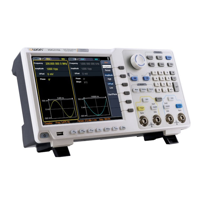
OWON OWON XDG3102 2-ch Arbitrary Waveform Generator (100 MHz)
Features Advanced DDS technology, up to 250 MHz frequency output 1.25 GS/s sampling rate, and 1 μHz frequency resolution Up to 1M arbitrary waveform length Vertical resolution: 14 bits Comprehensive waveform output: 6 groups waveforms, and 152 group built-in arbitrary waveforms Comprehensive modulation options: AM, FM, PM, FSK, 3FSK, 4FSK, PSK, OSK, ASK, BPSK, PWM, sweep, and burst High-accuracy frequency counter integrated, ranging from 100MHz till 200MHz SCPI and LabVIEW supported 8-inch 800 x 600 pixels touch screen LCD Specifications XDG3102 Channel 2 Frequency Output 100MHz Sample Rate 1.25GSa/s Vertical Resolution 14 bits Waveform Standard Waveform sine, square, pulse, ramp, noise, and harmonic Arbitrary Waveform exponential rise, exponential fall, sin(x)/x, step wave, and others, total of 150 built-in waveforms, and user-defined arbitrary waveform Frequency (resolution 1μHz) Sine 1μHz - 100MHz Square 1μHz - 40MHz Pulse 1μHz - 25MHz Ramp 1μHz - 5MHz Harmonic 1μHz - 50MHz Noise 120MHz (-3dB, typical) Arbitrary Waveform built-in waveform: 1uHz - 15MHzuser-defined waveform: 1uHz - 50MHz Accuracy ±1ppm, 0°C - 40°C Amplitude Amplitude (50Ω) 1mVpp - 10Vpp (≤40MHz); 1mVpp - 5Vpp (≤80MHz) 1mVpp - 2.5Vpp (≤120MHz); 1mVpp - 1Vpp (≤250MHz) Amplitude(high impedance) 2mVpp - 20Vpp (≤40MHz); 2mVpp - 10Vpp (≤80MHz); 2mVpp - 5Vpp (≤120MHz); 2mVpp - 2Vpp (≤250MHz) Resolution 1mV or 4 digits DC Offset Range (50Ω) ±(5 Vpk - Amplitude Vpp/2) Range (high-Z, open circuit) ±(10 Vpk - Amplitude Vpp/2) Accuracy ±(1% of |setting| + 1mV + Amplitude Vpp x 0.5%) Resolution 1mV or 4 digits Load Impedance 50Ω (typical) Accuracy ±(1% of setting + 1 mVpp) (typical, 1kHz sine, 0V offset) Sine Wave Spectrum Purity Harmonic Distortion Typical (0dB) DC - 1MHz: <-65dBc 1MHz - 10MHz: <-60dBc 10MHz - 120MHz: <-50dBc 120MHz - 200MHz: <-45dBc Total Harmonic Distortion <0.05 %, 10 Hz to 20 kHz, 1 Vpp Spurious (non-harmonic), Typical (0dB) ≤10MHz: <-70dBc >10MHz: <-70dBc + 6dB/ octave Phase Noise Typical (0 dBm, 10 kHz deviation) 10MHz: ≤-110dBc/Hz Square Rise/Fall Time <5ns Overshoot <3% Duty Cycle 50.0% (fixed) Jitter (rms) 300ps + 100ppm Pulse Pulse Width 12ns - 996875s Leading/Trailing Edge Time ≧7ns Overshoot <3% Jitter (rms) 300ps + 100ppm Ramp Linearity ≤1% of peak output (typical, 1kHz, 1 Vpp, 50% symmetry) Symmetry 0% to 100% Harmonic Harmonic Order ≤16 Harmonic Type even, odd, all, user Harmonic Amplitude could be set for all the harmonics Harmonic Phase Arbitrary Waveform Length 2 points - 1M points Vertical Resolution 14 bits Minimum Rise/Fall Time <7ns Jitter (rms) 3ns Modulation Type AM, FM, PM, PWM, FSK, 3FSK, 4FSK, PSK, OSK, ASK, BPSK, sweep, and burst AM Carrier Waveform sine, square, ramp, and arbitrary (except DC) Source internal / external Modulating Waveform sine, square, ramp, noise, and arbitrary Depth 0.0% - 100.0% Modulating Frequency 2 mHz - 100 kHz FM Carrier Waveform sine, square, ramp, and arbitrary (except DC) Source internal / external Modulating Waveform sine, square, ramp, noise, and arbitrary Modulating Frequency 2 mHz - 100 kHz PM Carrier Waveform sine, square, ramp, and arbitrary (except DC) Source internal / external Modulating Waveform sine, square, ramp, noise, and arbitrary Phase Deviation 0° - 180° Modulating Frequency 2 mHz - 100 kHz PWM Carrier Waveform pulse Source internal / external Modulating Waveform sine, square, ramp, noise, and arbitrary Width Deviation 0 ~ minimum (pulse duty ratio, 100% - pulse duty ratio) Modulating Frequency 2 mHz - 100 kHz FSK / 3FSK / 4FSK Carrier Waveform sine, square, ramp, and arbitrary (except DC) Source internal / external Modulating Waveform square with 50% duty cycle Key Frequency 2 mHz - 1MHz PSK Carrier Waveform sine, square, ramp, and arbitrary (except DC) Source internal / external Modulating Waveform square with 50% duty cycle Key Frequency 2 mHz - 1MHz OSK Carrier Waveform sine, square, ramp, and arbitrary (except DC) Source internal Oscillation Time square with 50% duty cycle Key Frequency 2 mHz - 1MHz ASK Carrier Waveform sine, square, ramp, and arbitrary (except DC) Source internal / external Modulating Waveform square with 50% duty cycle Key Frequency 2 mHz - 1MHz BPSK Carrier Waveform sine, square, ramp, and arbitrary (except DC) Source internal Modulating Waveform square with 50% duty cycle Key Frequency 2 mHz - 1MHz Sweep Carrier Waveform sine, square, ramp, and arbitrary (except DC) Type linear, and log Direction up, and down Sweep Time 1 ms to 500s, ± 0.1% Trigger Source internal, external, and manual Burst Carrier Waveform sine, square, ramp, pulse, and arbitrary (except DC) Burst Count 1 to 50,000 period, infinite, gating Internal Period 10 ns - 500 s Gated Source external trigger Frequency Counter Function frequency period, +width, -width, +duty, and -duty Frequency Range 100 MHz - 200 MHz Frequency Resolution 7 digits Input / Output Display 8”800 x 600 pixels touch screen LCD Type frequency counter, external modulation input,external trigger input,external reference clock input / output Communication Interface USB Host, USB Device, and LAN Dimension 340 x 177 x 90 mm Weight 2.50 kg
€ 650,00
-

Elektor Digital Radio-Baubuch (E-book)
Radio-Baubuch (E-book)
€ 29,80
Members: € 26,82
-
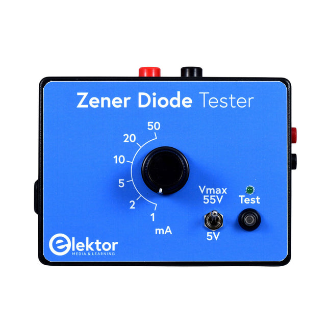
Elektor Zener Diode Tester
The Elektor Zener Diode Tester is essentially a constant-current source that can be switched in steps from 1 to 50 mA. It can be used to test Z-diodes up to a maximum of 54 V. Thanks to a 60-V step-up converter, the device can be powered by the usual 5 to 12 V. The principle of this tester is straightforward. A Z-diode or other DUT (device under test, such as an LED) is biased by an adjustable current source. The voltage across the DUT can be measured with a multimeter. The voltage of most (small) Z-diodes is specified at a current of 5 mA. Depending on the application, the voltage at other currents can also be of interest. That is why six current settings are available: 1, 2, 5, 10, 20, and 50 mA. LEDs are often specified at a current of 20 mA. What can be tested is: Whether a Z-diode is defective (short circuit or high impedance). Whether a Z-diode exhibits the correct Z-voltage. How a Z-voltage changes with different currents. What exact voltage is present at an integrated voltage reference. Whether LEDs in a series chain differ in brightness (hence the 20 mA current). What the current gain is for different base currents in (power) transistors. The kit contains all parts listed in the bill of materials including PCB and enclosure. Specifications Supply voltage 5…12 V/2 A (USB-C) Supply current (Itest = 50 mA) 1.1 A @ 5 V / 412 mA @ 12 V Selectable currents 1, 2, 5, 10, 20, and 50 mA Max. test voltage >54 V @ Itest ≥1 mA Max. output voltage 60 V @ Itest = 0 mA Voltage limit at 5 V 4.5 V @ Itest = 1 mA / 5.18 V @ Itest = 50 mA Enclosure dimensions 110 x 82 x 44 mm PCB size 105.4 x 67.3 mm Connections 4 mm banana sockets for multimeter 2 mm banana sockets for test clips USB-C socket for power supply Included Resistors R1 = 3.3 kΩ, 600 mW, 1% R2 = 0.15 Ω, 1 W, 5%, LS 12.7 mm, ø 3.5 mm R3, R8 = 180 Ω, 600 mW, 1% R4, R6, R16 = 1 kΩ, 600 mW, 1% R5, R19 = 47 kΩ, 600 mW, 1% R7 = 3.9 kΩ, 1 W, 5%, LS 12.7 mm, ø 3.5 mm R9, R10, R12 = 10 kΩ, 600 mW, 1% R11, R13 = 100 Ω, 600 mW 1% R14 = 249 Ω, 600 mW, 1% R15 = 499 Ω, 600 mW, 1% R17 = 2.49 kΩ, 250 mW, 1% R18 = 4.99 kΩ, 250 mW, 1% Capacitors C1 = 470 uF / 35 V, 20%, Ir = 1.86 A, ø 12.5 mm, LS 5 mm, ESR = 0.038 Ω (Panasonic EEUTP1V471) C2 = 1 uF / 100 V, 10%, X7R, LS 5 mm C3 = 2.2 nF / 50 V, 10%, X7R, LS 5 mm C4, C7 = 100 nF / 100 V, 10%, X7R, LS 5 mm C5 = 100 uF / 100 V, 20%, ø 14 mm max., LS 5 mm C6 = 1 nF / 100 V, 10%, X7R, LS 5 mm Inductor L1 = 100 uH, Irms = 2.4 A, Isat = 3.5 A, 0.09 Ω, radial, pitch 2.5/5/10 mm, ø 14 mm max. (Kemet SBC8-101-242) Semiconductors D1 = MUR120G, DO-41 D2, D4 = STPS3150RL, DO-201AD D3 = Z-diode, 18 V, 1.3 W (BZX85C18) D5 = Z-diode, 5.1 V, 0.5 W (1N5231B) LED1 = LED in pushbutton S1 LED2 = LED, green, 3 mm IC1 = MC34063, DIP-8 IC2 = LM4040BIZ-5.0/NOPB, TO-92 (TO-226AA-3) IC3 = TL051CP, DIP-8 T1 = BC327.25, TO-92 T2 = STP40NF10L, TO-220 T3 = IRF9510PBF, TO-220 T4 = 2N7000, TO-92 Others K1, K2, S1, S3 = 2-way screw terminal block, LS 3.5 mm, max. 1.5 mm² connected to K1 = USB-C socket, 30 V/3 A, chassis mounted, wired, 9 x 16 mm connected to K2 = Banana Connector, 2 mm, Socket, 60 VDC, Panel Mount, red (Multicomp 24.102.1) connected to K2 = Banana Connector, 2 mm, Socket, 60 VDC, Panel Mount, black (Multicomp 24.102.2) Test clip, red, 30 VAC/60 VDC (Hirschmann 931467101) Test clip, black, 30 VAC/60 VDC (Hirschmann 931467100) S1 = Pushbutton, panel mount, SPST-NO, 30 DC/100 mA, with red LED S2 = Rotary Switch, 6 position, 2 pole, 30°, 250 V/150 mA S3 = Toggle switch, panel mount, SPDT, solder lugs, 28 VDC T2, T3 = Heat sink, 15°C/W, FK 214 SA-CB Enclosure Hammond 1591XXSSBK, ABS, 110 x 82 x 44 mm Knob for S2, round shaft 6 mm, ø 21 mm, with indicator line (Multicomp CP-LB21-6-6D) 4 x Self-tapping screw #4-1/4", carbon steel, pan head Banana plug, red, 2 mm, 60 VDC (Multicomp 25.205.1) Banana plug, black, 2 mm, 60 VDC (Multicomp 25.205.2) Banana socket, black 4 mm, panel mount Banana socket, red 4 mm, panel mount for LED1, LED2 = Pin header, 1 x 2, vertical, pitch 2.54 mm for LED1, LED2 = Pin socket, 1 x 2, vertical, pitch 2.54 mm for T2, T3 = M3 screw, 10 mm, steel, pan head 2 x M3 washer, plain, steel 4 x M3 nut for IC1, IC3 = DIP-8 socket Wire, black, 0.25 mm² (24 AWG), stranded 14 x 0.15 mm, 1 m Wire, red, 0.25 mm² (24 AWG), stranded 14 x 0.15 mm, 1 m PCB 250772-1 v1.1 Links Article Elektor Labs
€ 99,95€ 79,95Best Price
-

Elektor Digital Retro Radio (E-book) NL
Retro Radio is een praktijkboek voor beginners en uitermate geschikt voor iedereen die wel eens een radio zou willen bouwen en meer wil weten over de radiotechniek. Na een inleiding in de beginselen van de techniek en de radio-ontvangst op de korte golf komen een aantal eenvoudige radio-ontwerpen aan bod. Het gaat om radio’s voor de middengolf en korte golf, waarbij de KG radio’s geschikt zijn voor de ontvangst van Single Side Band signalen. Het “retro” karakter dankt het boek aan het feit dat de gepubliceerde schakelingen klassiekers zijn uit de analoge radiotechniek. Ze zijn geïnspireerd door schakelingen uit de jaren ’50 en de begintijd van de radiotechniek. De auteur grijpt terug op de radio in zijn meest elementaire vorm. Al het “overbodige” is uit de schakelingen weggelaten. Er wordt gewerkt met spoelen, afstemcondensatoren, keramische filters en spoelfilters. Alle schakelingen zijn gebouwd met gewone transistors en een veldeffecttransistor. Elektronische chips worden niet gebruikt. Overigens is aan de nieuwste ontwikkelingen niet helemaal voorbij gegaan. Er is ook een SDR ontwerp opgenomen. Een greep uit de schema’s: een kristalradio, verschillende middengolf ontvangers (ook met een radiobuis), een “oer” schema geïnspireerd door de begintijd van de radio, twee korte golf ontvangers met SSB (2-12 MHz en 6-17 MHz) en een ontvanger voor de 80 meter band. Verder is in dit boek bijzonder veel aandacht besteed aan de praktische constructie van de radio’s en zijn er verschillende eenvoudige meetapparaten beschreven die dienst kunnen doen bij het ontwerpen en testen van radio’s (meetzender, absorptiemeter, transistortester e.d.).
€ 24,95
Members: € 22,46
-

Elektor Digital Nucleo Boards Programming with the STM32CubeIDE (E-book)
Hands-on in more than 50 projects STM32 Nucleo family of processors are manufactured by STMicroelectronics. These are low-cost ARM microcontroller development boards. This book is about developing projects using the popular STM32CubeIDE software with the Nucleo-L476RG development board. In the early Chapters of the book the architecture of the Nucleo family is briefly described. The book covers many projects using most features of the Nucleo-L476RG development board where the full software listings for the STM32CubeIDE are given for each project together with extensive descriptions. The projects range from simple flashing LEDs to more complex projects using modules, devices, and libraries such as GPIO, ADC, DAC, I²C, SPI, LCD, DMA, analogue inputs, power management, X-CUBE-MEMS1 library, DEBUGGING, and others. In addition, several projects are given using the popular Nucleo Expansion Boards. These Expansion Boards plug on top of the Nucleo development boards and provide sensors, relays, accelerometers, gyroscopes, Wi-Fi, and many others. Using an expansion board together with the X-CUBE-MEMS1 library simplifies the task of project development considerably. All the projects in the book have been tested and are working. The following sub-headings are given for each project: Project Title, Description, Aim, Block Diagram, Circuit Diagram, and Program Listing for the STM32CubeIDE. In this book you will learn about STM32 microcontroller architecture; the Nucleo-L476RG development board in projects using the STM32CubeIDE integrated software development tool; external and internal interrupts and DMA; DEBUG, a program developed using the STM32CubeIDE; the MCU in Sleep, Stop, and in Standby modes; Nucleo Expansion Boards with the Nucleo development boards. What you need a PC with Internet connection and a USB port; STM32CubeIDE software (available at STMicroelectronics website free of charge) the project source files, available from the book’s webpage hosted by Elektor; Nucleo-L476RG development board; simple electronic devices such as LEDs, temperature sensor, I²C and SPI chips, and a few more; Nucleo Expansion Boards (optional).
€ 39,95
Members: € 35,96
-
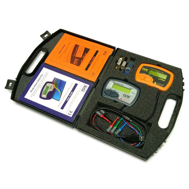
Peak Peak Atlas Pro Pack (LCR45 & DCA75)
This pack contains the LCR45 Passive Component Impedance Meter, great for advanced hobbyists and professionals. It also contains the very popular DCA Pro (model DCA75), fantastic for component identification, pinout identification, detailed characteristic measurement and curve tracing on a PC. Complete with USB cable and software on a USB flash drive. DCA75 Building on the continued success of Peak's existing component identification and analysis instruments, the DCA Pro brings an array of exciting new features for the hobbyist and professional alike. The DCA Pro is an advanced new design that features a graphics display, USB communications, PC Software and an enhanced component identification library. Automatic component type identification Automatic pinout identification (connect any way round) The DCA Pro supports all the components that the popular Peak Atlas DCA55 supports, but adds plenty more. Components supported include: Transistors (including Darlingtons), Silicon and Germanium types. Measures gain, Vbe and leakage MOSFETs, enhancement mode and depletion mode types. Measure on-threshold (at 5 mA) and approx transconductance (for span of 3-5 mA) JFETs, including normally off SiC types. Measures pinch-off voltage (at 1 uA) and approx transconductance (for span of 3-5 mA) IGBTs (insulated gate bipolar transistors). Measures on-threshold (at 5 mA) Diodes and Diode networks LEDs and bicolour LEDs (2 lead and 3 lead types) Zener Diodes with measurement of zener voltage up to 9 V at 5 mA Voltage regulators (measures regulation voltage, drop-out voltage, quiescent current) Triacs and Thyristors that require less than 10 mA of gate current and holding current Stand-alone or with a PC The instrument can be used stand-alone or connected to a PC. Either way, the DCA Pro will automatically identify the component type, identify the pinout and also measure a range of component parameters such as transistor gain, leakage, MOSFET and IGBT threshold voltages, pn characteristics and much more. Curve Tracing When connected to a PC using the supplied USB cable, a range of low current curve-tracing functions can be performed. Various graph types are available, with more to follow: Bipolar transistor output characteristics, IC vs VCE Bipolar transistor gain characteristics, HFE vs VCE Bipolar transistor gain characteristics, HFE vs IC MOSFET and IGBT output function, ID vs VDS MOSFET and IGBT transfer function, ID vs VGS JFET output function, ID vs VDS JFET transfer function, ID vs VGS Voltage regulator, VOUT vs VIN Voltage regulator, IQ vs VIN. PN junction I/V curves, forward and reverse options (for Zener diodes) Curve tracing is performed using test parameters in the range of +/-12 V or +/-12 mA. All curve-tracing data can be instantly pasted into Excel for further graphing and analysis. PC Software is included with the DCA Pro on a Peak USB memory stick. Software designed for Windows 7 and higher (all 32 or 64 bit). LCR45 A great handheld LCR analyzer that can measure the value of your passive component (inductor, capacitor or resistor) and also measure the detailed impedance in a number of modes. The LCR45 offers enhanced measurement resolution (better than 0.1 uH!) whilst also giving you continuous fluid measurements. Additionally, the test frequencies of DC, 1 kHz, 15 kHz and 200 kHz can be set to automatic or manual modes. Supplied with removable gold plated hook probes, battery and user guide. Compatible with standard 2 mm test connectors. Not designed for in-circuit use. Automatic or manual component type selection: Inductor, Capacitor or Resistor Automatic or manual test frequency selection: DC, 1 kHz, 15 kHz and 200 kHz Inductance from 0.1 uH to 10 H Capacitance from 0.1 pF to 10,000 uF Resistance from 0.1 Ohm to 2 MOhm Inductance measurement also shows DC winding resistance Display of "Component type and values", "Complex Impedance", "Magnitude/Phase" and "Admittance" Test frequency displayed for all measurements Typical accuracy of 1.5% for inductors and capacitors (see spec table for details) Typical accuracy of 1% for resistors Test lead complete with gold plated 2 mm plugs and sockets Supplied with removable gold plated hook probes Included LCR45 DCA75 Extra GP23 Battery Extra AAA cell Dual Carry Case
€ 325,49
-
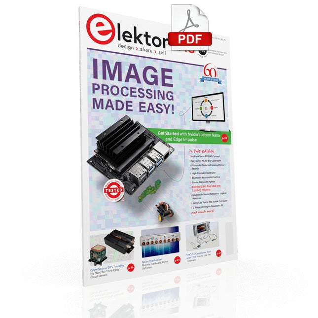
Elektor Digital Elektor November/December 2021 (PDF)
IMAGE PROCESSING WITH THE NVIDIA JETSON NANO (PART 2)Image Recognition Using Edge Impulse ELEKTOR JUMPSTARTER NEWSUpcoming Campaigns AN OPEN-SOURCE GPS TRACKING PLATFORMTraccar Maps Vehicle Tracking Without the Need for a Third-Party Cloud Server JOY-IT LCR-T7 MULTI-FUNCTION TESTERTesting Passives, Discrete Semiconductors and IR Remote Controls NOISE SYNTHESIZERFrom Noise to Music with the PRBSynth1 STARTING OUT IN ELECTRONICSEasier than Imagined! ... Continuing with the Coil UNDERSTANDING THE NEURONS IN NEURAL NETWORKS (PART 2)Logical Neurons ISSUES WITH SECURITY? FIGHT FIRE WITH FIRE!Flashbulb-Protected Analogue Memory Add-on For the Tamper-Evident Box LCR METER POSTER BLUETOOTH BEACONS IN PRACTICEBeacons Light the Way Ahead C PROGRAMMING ON RASPBERRY PICommunicating over Wi-Fi (Sample Chapter) EMC PRE-COMPLIANCE TEST FOR YOUR DC-POWERED PROJECT (PART 2)The Hardware and How to Use It HANDS ON THE PARALLAX PROPELLER 2 (PART 5)Inside the Smart Pin MODBUS OVER WLAN (PART 1)Hardware and Programming HOMELAB TOURSWhere the Junior Computer Is Brought to Life Again BUILD YOUR OWN HIGH-PRECISION CALIBRATOR-10 V to +10 V, 0 to 40 mA, 0.001% ARDUINO NANO RP2040 CONNECTRaspberry Pi RP2040 + Wi-Fi + Bluetooth THE PHYSICAL BODY OF ARTIFICIAL INTELLIGENCE ERR-LECTRONICSCorrections, Updates and Readers’ Letters CREATE GUIS WITH PYTHONIntroducing guizero CO2 METER KIT FOR THE CLASSROOMAn ESP8266-Based Device from the University of Applied Sciences Aachen NOSTALGIC MK484 MW/LW RADIO...Always Fun to Build! ELEKTOR @ 60Let There Be Light! HEXADOKUThe Original Elektorized Sudoku
€ 7,50
-

Elektor Classics Elektor Archive 1974-2025 (USB Stick) EN
52 Volumes on USB – Now incl. Volume 2025! NEW: For articles from the year 2000 onwards, there is now a separate download option for additional materials such as PCB layouts, Gerber files, and software! This USB stick (64 GB) is loaded with all the Elektor magazine English editions (as PDFs) from 1974 to 2025. Elektor engineers, authors, and editors aim to inspire you to master electronics and computer technology by presenting professionally designed circuits that are easy to build. We also cover the latest developments in electronics and information technology. With the Elektor Archive on a USB stick, you can browse our previous English editions at your convenience and learn about MCU-based projects, robotics, electronics testing, embedded programming, analog techniques, and much more. All the Elektor magazine editions are stored as PDFs on a 32-GB USB stick (USB 3.0). The 10,000+ articles have been classified by date of publication (month/year), and a comprehensive index enables you to search the entire USB stick. Subject areas include: Audio & video Computers & microcontrollers Radio, hobby & modelling Home & garden Power supplies & batteries Test & measurement Software And everything else that doesn’t fit in one of these categories. Elektor GPT Elektor GPT is an AI-powered tool that helps users navigate through the decades-long Elektor archive. Using advanced search algorithms and natural language processing, Elektor GPT quickly finds articles, projects, and other resources from the archive. Specifications Storage 64 GB Interfaces 1x USB-A1x USB-C System requirements PC with Adobe Reader 7.0 or higher Web browser
€ 199,95€ 99,95Best Price


