
Search results for "labnation or smartscope or usb or oscilloscope"
-
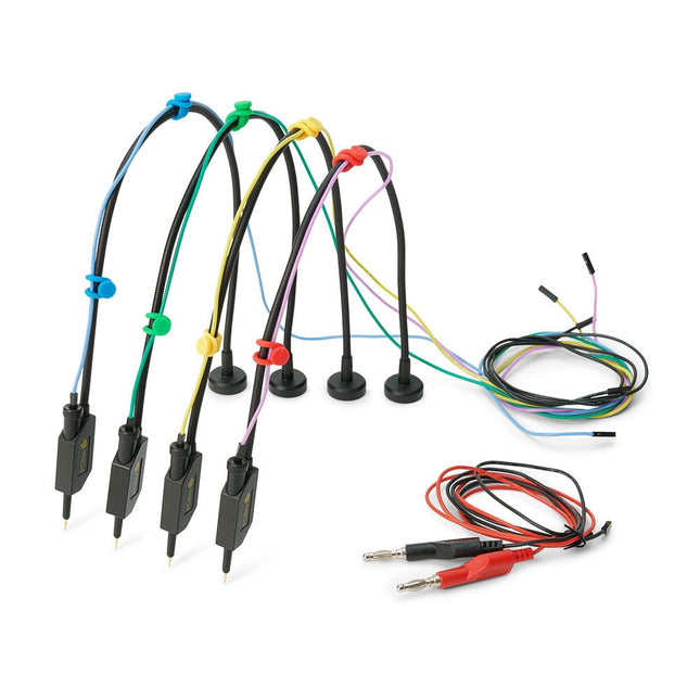
Sensepeek Sensepeek 6005 4x SQ10 Probe incl. Test Wires
The SQ series of handsfree PCBite probes from Sensepeek are insulated, come with included color-coded cable holders and have a lower point of gravity making them even more stable compared with the original SP series of probes. All the loved features of handsfree measurement, exchangeable fine pitch spring tipped test needle and the minimalistic design is maintained to make traditional sized and handheld probes obsolete. Features All handsfree probes from Sensepeek makes instant measurements or long triggering sessions a breeze. No more soldering wires to connect your probe or complicated tools to setup, just positioning the probe needle on any test point or component in the signal path and release. Saves time and frustration during development, verification and repairs. The minimalist design and the spring-loaded test needle makes it possible to simultaneously measure on fine pitch components and nearby signals. Both length and weight of the SQ probes are perfectly balanced to be used with PCBite PCB holders and base plate which is a must for handsfree function. The probe holder comes with a powerful magnet in the base, as for all PCBite probes and holders which makes the probe easy to place and reposition. The SQ series of probes can be used handheld without the probe holder as they have an insulated grip but their full potential is used when measuring handsfree. Included 4x SQ10 probes and pin tipped test needles (black) 2x Banana to dupont test wires (red/black) 5x Dupont to dupont test wires 1x Set of cable holders (4 colors) 4x Extra test needles Downloads User guide
€ 107,69
-
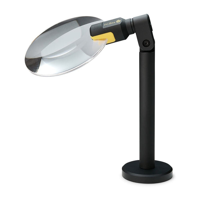
Sensepeek Sensepeek 4020 PCBite 3x Magnifier
The PCBite Magnifier (premium build quality made from CNC machined aluminum) enlarges your target and makes it easier to see during soldering, inspection and measurements. Especially useful when placing PCBite hands free probes on fine pitch SMD components during measurements. 3x magnification edgeless lens for increased visibility of the work surface and AR coating (anti-reflection) to reduce reflections from nearby light sources. Optimized design, magnification and focal point for use together with the PCBite PCB holders and baseplates included in all PCBite kits. Can also be used handheld but not standalone without a metal surface as base. At the bottom of the magnifier foot there is a strong magnet perfectly balanced in strength. A low friction bottom cap protects the magnet and the baseplate to make the magnifier easy to slide when repositioning or removing the magnifier from the baseplate. Friction based adjustment of lens tilt and rotate positions takes away the need for annoying and complicated set screws.
€ 71,39
-
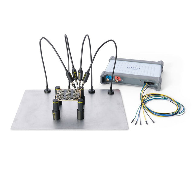
Sensepeek Sensepeek 4003 PCBite Kit incl. 4x SP10 Probe and Test Wires
The minimalist design and the spring loaded test needle makes it possible to simultaneously measure on fine pitch components and nearby signals. The probe is steady but yet flexible made for instant measurements or total hands-free operations together with your multimeter, logic analyzer or preferred tool. The dual pin header connector fits directly on a 2.54 mm (0.100”) connector. The SP10 comes with a powerful magnet in the base, as for all PCBite probes and holders which makes the probe easy to place and reposition. Included 4x PCBite holder 1x Large base plate (A4) 4x PCBite probe with pin tipped test needle 4x Extra crown tipped test needle 1x Set of yellow insulation washers 5x Dupont to dupont test wire 2x Banana to dupont test wire 1x Microfiber cloth Downloads User Guide
€ 152,46
-

Elektor July/August 2026 (EN)
Elektor GREEN and GOLD members can download their digital edition here. Not a member yet? Click here. MultiRF Dev BoardA Platform for Evaluating Short- and Long-Range Wireless Protocols Elektor at 65Disrupting Electronics Since 1961 Wi-Fi-Based Person Detection on an ESP32When Your Router Becomes a Motion Sensor Wireless ScalesFour Small Scales = One Big Scale Walter, the Compact IoT ModuleESP32-S3 SoC, LTE-M/NB-IoT 5G Modem, and GNSS Receiver 3- and 4-Wire RTD Sensors ConditioningWith Full-Scale Adjustment and Cable Compensation 3-in-1 2-Channel Oscilloscope/Generator/MultimeterA Review of The Fnirsi 2D15P electronica Fast Forward 2026 Invites Startups and Industry Partners EcologgingA Modular Environmental IoT Station for Field Research Wireless Connectivity in Medical ApplicationsAlways on the Pulse with Bluetooth LE AudiotronicsHum Reduction Increasing Agricultural Efficiency with AI Modeling and SensorsBoosting Agricultural Productivity OPC UA — An OverviewPlatform-Independent Data Exchange Redox Meter Instrumentation Amplifier for Physics and Engineering Experiments Active Differential Audio FiltersFor Professional Crossovers and More Elektor Community Perspectives on IoT & Sensors Telegram-Controlled Water Heater Interface ModuleA Solution Based on an ESP32 and Arduino Software 2026: An AI OdysseyWhatever Happened to Fuzzy Logic? Err-lectronics Alarm Signal Injector Plus PowerTools for Finding Broken Wires
€ 14,90
-
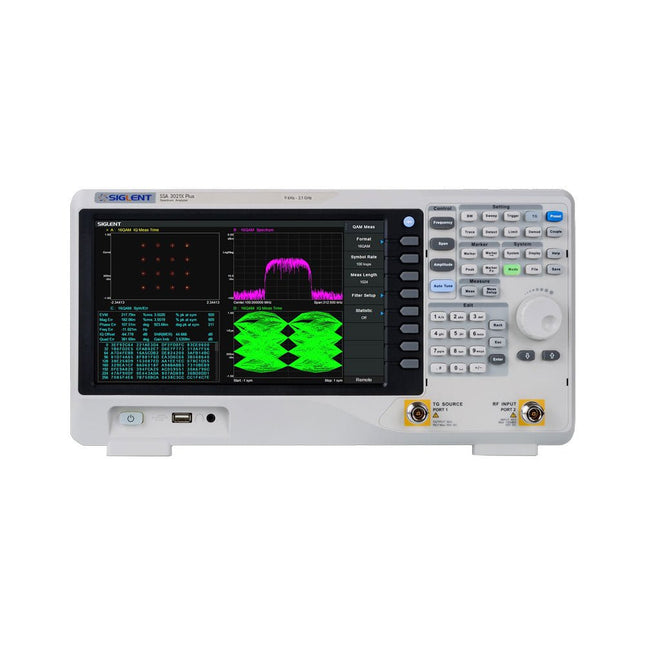
Siglent Siglent SSA3021X Plus Spectrum Analyzer (9 kHz – 2.1 GHz)
The Siglent SSA3021X Plus spectrum analyzer is a powerful and flexible tool for RF signal and network analysis. With a frequency range of 2.1 GHz, the analyzer delivers reliable automatic measurements and multiple modes of operation: spectrum analyzer the base, optional functions include RF power measurement, vector signal modulation analysis, reflection measurement, and EMI test. Applications include broadcast monitoring/evaluation, site surveying, S-parameter measurement, analog/digital modulation analysis, EMI pre-compliance test, research and development, education, production, and maintenance. Features Spectrum Analyzer Frequency Range from 9 kHz to 2.1 GHz –161 dBm/Hz Displayed Average Noise Level (Typ.) –98 dBc/Hz. @ 10 kHz Offset Phase Noise (1 GHz, Typ.) Level Measurement Uncertainty <0.7 dB (Typ.) 1 Hz Minimum Resolution Bandwidth (RBW) Preamplifier (Std.) Tracking Generator (incl. free of charge) Analog and Digital Signal Modulation Analysis Mode (opt.) Reflection Measurement Kit (opt.) EMI Filter and Quasi-Peak Detector Kit (opt.) Advanced Measurement Kit (opt.) 10.1-inch Multi-Touch Screen , Mouse and Keyboard supported Web Browser Remote Control on PC and Mobile Terminals and File Operation Specifications SSA3015X Plus SSA3021X Plus SSA3032X Plus SSA3075X Plus Frequency Range 9 kHz ~ 1.5 GHz 9 kHz ~ 2.1 GHz 9 kHz ~ 3.2 GHz 9 kHz ~ 7.5 GHz Resolution Bandwidth 1 Hz ~ 1 MHz 1 Hz ~ 1 MHz 1 Hz ~ 1 MHz 1 Hz ~ 3 MHz Phase Noise <–99 dBc/Hz <–98 dBc/Hz <–98 dBc/Hz <–98 dBc/Hz Total Amplitude Accuracy <1.2 dB <0.7 dB <0.7 dB <0.7 dB Display Average Noise Level –156 dBm/Hz –161 dBm/Hz –161 dBm/Hz –165 dBm/Hz Included Siglent SSA3021X Plus spectrum analyzer USB cable Power cord Quick start guide Downloads Datasheet Manual Documentation Firmware
€ 1.777,49
-

tinySA tinySA Ultra+ ZS407 Spectrum Analyzer
The tinySA Ultra+ ZS-407 is a compact, handheld spectrum analyzer and signal generator. Covering 100 kHz to 7.3 GHz in Ultra mode, it lets you visualize and analyze RF signals from HF right through many modern wireless bands – and can even spot signals up to ~12 GHz thanks to harmonic tracking. The intuitive 4-inch resistive touchscreen and rechargeable battery make it great for fieldwork, while features like a built-in signal generator, switchable bandpass filters, step attenuator, USB-PC control and auto-calibration add serious versatility. Features Screen size: 4 inch (480 x 320) Spectrum Analyzer for 0.1-900 MHz or, with Ultra mode enabled up to 7.3 GHz, level calibrated up to 7.3 GHz. Can observe signals up to 12 GHz Signal Generator with sine wave output between 0.1-900 MHz or square wave up to 6.3 GHz or RF test signal output up to 7.3 GHz when not used as Spectrum Analyzer. Switchable resolution bandpass filters from 200 Hz to 850 kHz Built-in 20 dB optional LNA Color display showing max 450 points providing gapless covering up to the full frequency range. MicroSD card slot for storing measurements, settings and screen captures. Specifications (Spectrum Analyzer) Input frequency range from 100 kHz to 900 MHz in normal mode and up to 7.3 GHz with ULTRA mode enabled Input impedance 50 ohm when input attenuation set to 10 dB or more. Selectable manual and automatic input attenuation between 0 dB and 31 dB in 1 dB steps when LNA not active Maximum +/-5V DC input Absolute maximum input level of +6 dBm with 0 dB internal attenuation Absolute maximum short term peak input power of +20 dBm with 30 dB internal attenuation Suggested maximum input power of +0 dBm with internal attenuation in automatic mode For best measurements keep input power below -25 dBm Input Intercept Point of third order modulation products (IIP3) of +15 dBm with 0 dB internal attenuation 1 dB compression point at -1 dBm with 0 dB internal attenuation Power detector resolution of 0.5 dB and linearity versus frequency of ±2 dB below 5.3 GHz, ±5dB between 5.3 GHz and 6 GHz Minimum burst length for correct level measurement at 850 kHz RBW in zero span mode of 50 microseconds Absolute power level accuracy after power level calibration of ±2 dB Built-in optional 20 dB LNA with Noise Figure of 5 dB up to 6 GHz Lowest discernible signal without LNA at 30 MHz using a resolution bandwidth of 30 kHz of -102 dBm Lowest discernible signal with LNA at 30 MHz using a resolution bandwidth of 200 Hz of -145 dBm Frequency accuracy equal to the selected resolution bandwidth Phase noise at 30 MHz of -108 dB/Hz at 100 kHz offset and -115 dB/Hz at 1MHz offset Spur free dynamic range when using a 30 kHz resolution bandwidth of 70 dB Resolution filters with a width of 0.2, 1, 3, 10, 30, 100, 300, 600 and 850 kHz On screen resolution of 51, 101, 145, 290 or 450 measurement points. Scanning speed of over 1000 points/second using largest resolution filters. Automatic optimization of actual scanning points to ensure coverage of the whole scan range regardless of the chosen resolution bandwidth Spur suppression option for assessing if certain signals are internally generated or actually present in the input signal Headphone output for listening to the demodulated audio (AM only). Stereo connector with or without microphone, high impedance is louder, short protected Specifications (Signal Generator) Sine wave output with harmonics below -40 dB of fundamental from 100 kHz to 900 MHz Output level selectable in 1 dB steps between -115 dBm and -19 dBm Above 800 MHz choice of two output modes: Cleanest signal mode: square wave, up to 6 GHz with coarse frequency steps and less accurate output level Highest accuracy mode: reduced harmonics with possibly strong spurs up to 7.3 GHz with frequency resolution equal to below 800 MHz and fine output level steps Level accuracy ±2 dB up to 800 MHz between -72 dBm and -19 dBm, less accuracy below -72 dBm, even less accuracy below -110 dBm Output frequency resolution 57.2 Hz Optional AM or FM modulation frequencies between 50 Hz and 5 kHz (AM) or 1 kHz (FM) or sweep over selectable frequency span AM modulation depth between 10% and 100% FM deviation between 1 kHz and 300 kHz Optional output level sweep over maximum the entire output level range Included 1x tinySA Ultra+ ZS407 Spectrum Analyzer 2x SMA connection cables 1x Barrel connector 1x Antenna with SMA connector 1x USB-C cable 1x microSD card (32 GB) Downloads Wiki
€ 196,02
-

Elektor Digital Logic Analyzer im Einsatz (PDF)
USB-Logikanalysatoren am PC mit Arduino, Raspberry Pi und Co Schritt-für-Schritt-Anleitungen führen Sie in die Analyse moderner Protokolle von I²C, SPI, UART, RS-232, NeoPixel, WS28xx, HD44780 und 1-Wire ein. Anhand von zahlreichen Experimentierschaltungen mit dem Raspberry Pi Pico, Arduino Uno und dem Bus Pirate üben Sie die praxisnahe Anwendung gängiger USB-Logikanalysatoren ein. Alle in diesem Buch vorgestellten Experimentierschaltungen wurden vollständig getestet und sind funktionsfähig. Die notwendigen Programmlistings sind enthalten, es sind keine besonderen Programmier- oder Elektronikkenntnisse für diese Schaltungen notwendig. Es werden die Programmiersprachen MicroPython und C mit den Entwicklungsumgebungen Thonny und Arduino IDE eingesetzt. Dieses Buch verwendet mehrere Modelle flexibler und weit verbreiteter USB-Logikanalysatoren und zeigt die Stärken und Schwächen jeder Preisklasse. Sie werden kennenlernen, welche Kriterien für Ihre Arbeit wichtig sind und in der Lage sein, das für Sie passende Gerät zu finden. Egal ob Arduino, Raspberry Pi oder Raspberry Pi Pico: Die abgebildeten Beispielschaltungen ermöglichen einen schnellen Start in die Protokollanalyse und können auch als Grundlage für eigene weitere Experimente dienen. Sie werden alle wichtigen Begriffe und Zusammenhänge kennenlernen, eigene Experimente durchführen, selbstständig Protokolle analysieren und nach der Lektüre dieses Buches – im Bereich der digitalen Signale und Protokolle – ein umfassendes Wissen aufgebaut haben.
€ 32,80
Members: € 29,52
-
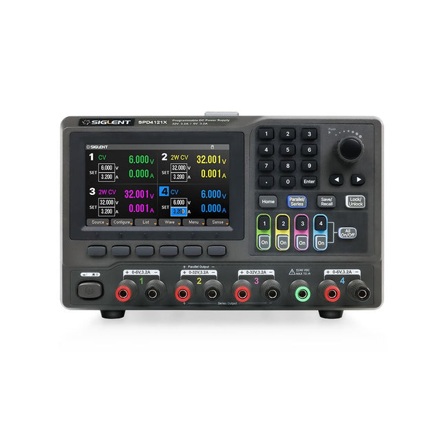
Siglent Siglent SPD4121X 4-ch DC Power Supply (285 W)
The Siglent SPD4121X is a 4-channel DC Linear Programmable Power Supply equipped with a 4.3-inch TFT-LCD display, friendly human-machine interface, and excellent performance indicators. Real-time waveform display provides engineers with an informative user interface. SPD4121X offers a total output power of 285 W with a resolution of 1 mV/1 mA. The maximum voltage and current for each channel are as follows: CH1: 15 V/1.5 A CH2: 12 V/10 A CH3: 12 V/10 A CH4: 15 V/1.5 A Features Rated output power: 285 W Rated voltage: 32 V, 12 V, 30 V Up to four high-precision power supplies with independent controllable outputs, supporting CH2 and CH3 series and parallel connections Clear graphical interface with waveform and timer display modes 5-digit voltage and current display with minimum resolution of 1 mV, 1 mA Fast output response time: <50us The high current channel support remote voltage compensation sense function. The maximum compensation voltage is 0.6 V Overvoltage protection and overcurrent protection or safe and accurate operation Equipped with a 4.3-inch TFT-LCD display (480 x 272 resolution) USB and LAN standard communication USB-GPIB module is optional Excellent channel density with up to 4 channels in a 3U half rack package Internal data storage for setups and parameters Embedded Web Server with instrument communication that doesn’t require software installation Fully SCPI programming command set support as well as a LabView driver for remote control and system automation Specifications SPD4323X SPD4121X SPD4306X Channel Output CH1: Voltage 0 to 6 V Current 0 to 3.2 ACH2: Voltage 0 to 32 V Current 0 to 3.2 ACH3: Voltage 0 to 32 V Current 0 to 3.2 ACH4: Voltage 0 to 6 V Current 0 to 3.2 A CH1: Voltage 0 to 15 V Current 0 to 1.5 ACH2: Voltage 0 to 12 V Current 0 to 10 ACH3: Voltage 0 to 12 V Current 0 to 10 ACH4: Voltage 0 to 15 V Current 0 to 1.5 A CH1: Voltage 0 to 15 V Current 0 to 1.5 ACH2: Voltage 0 to 30 V Current 0 to 6 ACH3: Voltage 0 to 30 V Current 0 to 6 ACH4: Voltage 0 to 15 V Current 0 to 1 A Resolution 1 mV, 1 mA 1 mV, 1 mA 1 mV, 1 mA Setting Accuracy Voltage: ±(0.03% of reading+10) mV, Current: ±(0.3% of reading+10) mA Voltage: ±(0.03% of reading+10) mV, Current: ±(0.3% of reading+10) mA Voltage: ±(0.03% of reading+10) mV, Current: ±(0.3% of reading+10) mA Readback Accuracy Voltage: ±(0.03% of reading+10) mV, Current: ±(0.3% of reading+10) mA Voltage: ±(0.03% of reading+10) mV, Current: ±(0.3% of reading+10) mA Voltage: ±(0.03% of reading+10) mV, Current: ±(0.3% of reading+10) mA Display 4.3" TFT-LCD 5-digit voltage and current display 4.3" TFT-LCD 5-digit voltage and current display 4.3" TFT-LCD 5-digit voltage and current display Output power 240 W 285 W 400 W Included 1x Siglent SPD4121X Power Supply 1x Power cord (EU) 1x Output test cord (3 A) 1x USB cable 1x Quick start guide Downloads Datasheet Manual Quick start
€ 871,20
-

Elektor Digital PIC Cookbook for Virtual Instrumentation (E-book)
The software simulation of gauges, control-knobs, meters and indicators which behave just like real hardware components on a PC’s screen is known as virtual instrumentation. In this book, the Delphi program is used to create these mimics and PIC based external sensors are connected via a USB/RS232 converter communication link to a PC. Detailed case studies in this Book include a virtual compass displayed on the PC’s screen, a virtual digital storage oscilloscope, virtual -50 to +125 degree C thermometer, and FFT sound analyser, a joystick mouse and many examples detailing virtual instrumentation Delphi components. Arizona’s embedded microcontrollers – the PIC's are used in the projects and include PIC16F84A, PIC16C71, DSPIC30F6012A, PIC16F877, PIC12F629 and the PIC16F887. Much use is made of Microchip’s 44 pin development board (a virtual instrument ‘engine)’, equipped with a PIC16F887 with an onboard potentiometer in conjunction with the PIC’s ADC to simulate the generation of a variable voltage from a sensor/transducer, a UART to enable PC RS232 communications and a bank of 8 LED's to monitor received data is also equipped with an ISP connector to which the ‘PICKIT 2’ programmer may easily be connected. Full source code examples are provided both for several different PIC’s, both in assembler and C, together with the Pascal code for the Delphi programs which use different 3rd party Delphi virtual components.
€ 19,95
Members: € 17,96
-
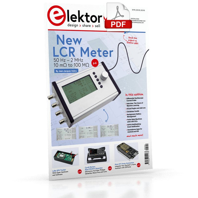
Elektor Digital Elektor November/December 2020 (PDF) EN
New LCR Meter 50 Hz - 2 MHz Part 1automatic impedance measuring bridge measures the resistance, capacitance and inductance of components with an impedance of 10 mΩ to 100 MΩ From Ding-Dong Door Chime to IoT DoorbellIntegrate your doorbell in Home Assistant with ESPHome Battery ManagementWhat to Be Aware of When Using (Lithium) Batteries Starting Out in ElectronicsEasier Than Imagined! Small Circuits RevivalFrom the Elektor Suggestions Box Breadboard Graphics with Fritzing Analogue Filter Design (Part 2)Active Filters Homelab Tours: The Lap CounterA Project for Mini Petrol-Heads Developer’s ZoneTips & Tricks, Best Practices and Other Useful Information Review: Rigol DS1054Z Four-Channel Oscilloscope Christmas CandleBlow It Out! Tunable Valve Sinewave Generator Retro is back! Review: The Rigol DG2072 Generator KiCad Plugins and Add-ons Differential Oscilloscope Current Probe 2.0Measure Currents Using Your Oscilloscope The Hewlett-Packard Interface LoopConnect the world! The Future of Machine LearningAn Interview with Daniel Situnayake Smartphone Apps for Android and iOSProgramming Apps Within a Single Development Environment From Life's ExperienceThe Value of a Technical Education 5G: How Infrastructure Shapes Our Society Practical ESP32 Multitasking (5)Task event notification HP 10811 OscillatorPeculiar Parts, the series LoRa GPS TrackerWith Open Hardware and Software Programming the Finite State Machinewith 8-bit PICs in Assembly and C
€ 7,50
-

Elektor Publishing Logic Analyzer im Einsatz
USB-Logikanalysatoren am PC mit Arduino, Raspberry Pi und Co Schritt-für-Schritt-Anleitungen führen Sie in die Analyse moderner Protokolle von I²C, SPI, UART, RS-232, NeoPixel, WS28xx, HD44780 und 1-Wire ein. Anhand von zahlreichen Experimentierschaltungen mit dem Raspberry Pi Pico, Arduino Uno und dem Bus Pirate üben Sie die praxisnahe Anwendung gängiger USB-Logikanalysatoren ein. Alle in diesem Buch vorgestellten Experimentierschaltungen wurden vollständig getestet und sind funktionsfähig. Die notwendigen Programmlistings sind enthalten, es sind keine besonderen Programmier- oder Elektronikkenntnisse für diese Schaltungen notwendig. Es werden die Programmiersprachen MicroPython und C mit den Entwicklungsumgebungen Thonny und Arduino IDE eingesetzt. Dieses Buch verwendet mehrere Modelle flexibler und weit verbreiteter USB-Logikanalysatoren und zeigt die Stärken und Schwächen jeder Preisklasse. Sie werden kennenlernen, welche Kriterien für Ihre Arbeit wichtig sind und in der Lage sein, das für Sie passende Gerät zu finden. Egal ob Arduino, Raspberry Pi oder Raspberry Pi Pico: Die abgebildeten Beispielschaltungen ermöglichen einen schnellen Start in die Protokollanalyse und können auch als Grundlage für eigene weitere Experimente dienen. Sie werden alle wichtigen Begriffe und Zusammenhänge kennenlernen, eigene Experimente durchführen, selbstständig Protokolle analysieren und nach der Lektüre dieses Buches – im Bereich der digitalen Signale und Protokolle – ein umfassendes Wissen aufgebaut haben.
€ 39,80
Best Price
-
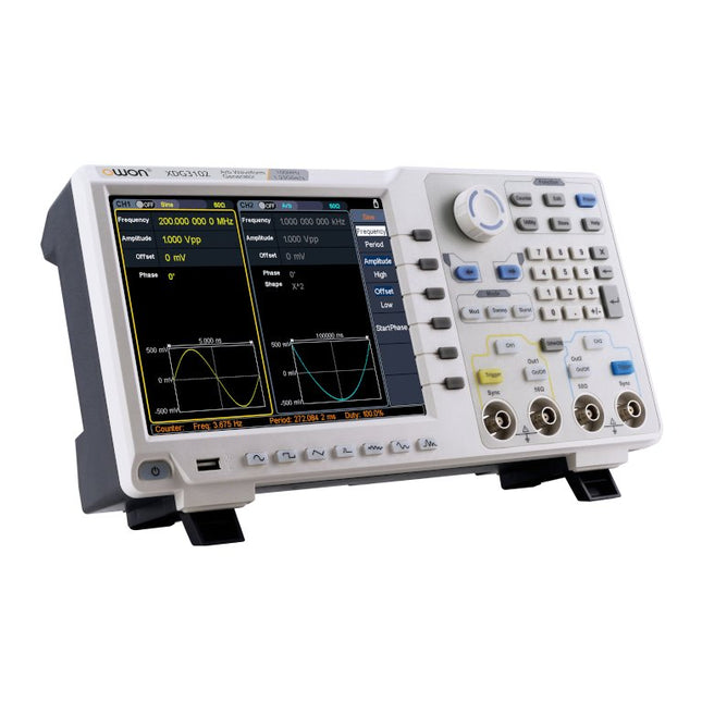
OWON OWON XDG3102 2-ch Arbitrary Waveform Generator (100 MHz)
Features Advanced DDS technology, up to 250 MHz frequency output 1.25 GS/s sampling rate, and 1 μHz frequency resolution Up to 1M arbitrary waveform length Vertical resolution: 14 bits Comprehensive waveform output: 6 groups waveforms, and 152 group built-in arbitrary waveforms Comprehensive modulation options: AM, FM, PM, FSK, 3FSK, 4FSK, PSK, OSK, ASK, BPSK, PWM, sweep, and burst High-accuracy frequency counter integrated, ranging from 100MHz till 200MHz SCPI and LabVIEW supported 8-inch 800 x 600 pixels touch screen LCD Specifications XDG3102 Channel 2 Frequency Output 100MHz Sample Rate 1.25GSa/s Vertical Resolution 14 bits Waveform Standard Waveform sine, square, pulse, ramp, noise, and harmonic Arbitrary Waveform exponential rise, exponential fall, sin(x)/x, step wave, and others, total of 150 built-in waveforms, and user-defined arbitrary waveform Frequency (resolution 1μHz) Sine 1μHz - 100MHz Square 1μHz - 40MHz Pulse 1μHz - 25MHz Ramp 1μHz - 5MHz Harmonic 1μHz - 50MHz Noise 120MHz (-3dB, typical) Arbitrary Waveform built-in waveform: 1uHz - 15MHzuser-defined waveform: 1uHz - 50MHz Accuracy ±1ppm, 0°C - 40°C Amplitude Amplitude (50Ω) 1mVpp - 10Vpp (≤40MHz); 1mVpp - 5Vpp (≤80MHz) 1mVpp - 2.5Vpp (≤120MHz); 1mVpp - 1Vpp (≤250MHz) Amplitude(high impedance) 2mVpp - 20Vpp (≤40MHz); 2mVpp - 10Vpp (≤80MHz); 2mVpp - 5Vpp (≤120MHz); 2mVpp - 2Vpp (≤250MHz) Resolution 1mV or 4 digits DC Offset Range (50Ω) ±(5 Vpk - Amplitude Vpp/2) Range (high-Z, open circuit) ±(10 Vpk - Amplitude Vpp/2) Accuracy ±(1% of |setting| + 1mV + Amplitude Vpp x 0.5%) Resolution 1mV or 4 digits Load Impedance 50Ω (typical) Accuracy ±(1% of setting + 1 mVpp) (typical, 1kHz sine, 0V offset) Sine Wave Spectrum Purity Harmonic Distortion Typical (0dB) DC - 1MHz: <-65dBc 1MHz - 10MHz: <-60dBc 10MHz - 120MHz: <-50dBc 120MHz - 200MHz: <-45dBc Total Harmonic Distortion <0.05 %, 10 Hz to 20 kHz, 1 Vpp Spurious (non-harmonic), Typical (0dB) ≤10MHz: <-70dBc >10MHz: <-70dBc + 6dB/ octave Phase Noise Typical (0 dBm, 10 kHz deviation) 10MHz: ≤-110dBc/Hz Square Rise/Fall Time <5ns Overshoot <3% Duty Cycle 50.0% (fixed) Jitter (rms) 300ps + 100ppm Pulse Pulse Width 12ns - 996875s Leading/Trailing Edge Time ≧7ns Overshoot <3% Jitter (rms) 300ps + 100ppm Ramp Linearity ≤1% of peak output (typical, 1kHz, 1 Vpp, 50% symmetry) Symmetry 0% to 100% Harmonic Harmonic Order ≤16 Harmonic Type even, odd, all, user Harmonic Amplitude could be set for all the harmonics Harmonic Phase Arbitrary Waveform Length 2 points - 1M points Vertical Resolution 14 bits Minimum Rise/Fall Time <7ns Jitter (rms) 3ns Modulation Type AM, FM, PM, PWM, FSK, 3FSK, 4FSK, PSK, OSK, ASK, BPSK, sweep, and burst AM Carrier Waveform sine, square, ramp, and arbitrary (except DC) Source internal / external Modulating Waveform sine, square, ramp, noise, and arbitrary Depth 0.0% - 100.0% Modulating Frequency 2 mHz - 100 kHz FM Carrier Waveform sine, square, ramp, and arbitrary (except DC) Source internal / external Modulating Waveform sine, square, ramp, noise, and arbitrary Modulating Frequency 2 mHz - 100 kHz PM Carrier Waveform sine, square, ramp, and arbitrary (except DC) Source internal / external Modulating Waveform sine, square, ramp, noise, and arbitrary Phase Deviation 0° - 180° Modulating Frequency 2 mHz - 100 kHz PWM Carrier Waveform pulse Source internal / external Modulating Waveform sine, square, ramp, noise, and arbitrary Width Deviation 0 ~ minimum (pulse duty ratio, 100% - pulse duty ratio) Modulating Frequency 2 mHz - 100 kHz FSK / 3FSK / 4FSK Carrier Waveform sine, square, ramp, and arbitrary (except DC) Source internal / external Modulating Waveform square with 50% duty cycle Key Frequency 2 mHz - 1MHz PSK Carrier Waveform sine, square, ramp, and arbitrary (except DC) Source internal / external Modulating Waveform square with 50% duty cycle Key Frequency 2 mHz - 1MHz OSK Carrier Waveform sine, square, ramp, and arbitrary (except DC) Source internal Oscillation Time square with 50% duty cycle Key Frequency 2 mHz - 1MHz ASK Carrier Waveform sine, square, ramp, and arbitrary (except DC) Source internal / external Modulating Waveform square with 50% duty cycle Key Frequency 2 mHz - 1MHz BPSK Carrier Waveform sine, square, ramp, and arbitrary (except DC) Source internal Modulating Waveform square with 50% duty cycle Key Frequency 2 mHz - 1MHz Sweep Carrier Waveform sine, square, ramp, and arbitrary (except DC) Type linear, and log Direction up, and down Sweep Time 1 ms to 500s, ± 0.1% Trigger Source internal, external, and manual Burst Carrier Waveform sine, square, ramp, pulse, and arbitrary (except DC) Burst Count 1 to 50,000 period, infinite, gating Internal Period 10 ns - 500 s Gated Source external trigger Frequency Counter Function frequency period, +width, -width, +duty, and -duty Frequency Range 100 MHz - 200 MHz Frequency Resolution 7 digits Input / Output Display 8”800 x 600 pixels touch screen LCD Type frequency counter, external modulation input,external trigger input,external reference clock input / output Communication Interface USB Host, USB Device, and LAN Dimension 340 x 177 x 90 mm Weight 2.50 kg
€ 650,00


