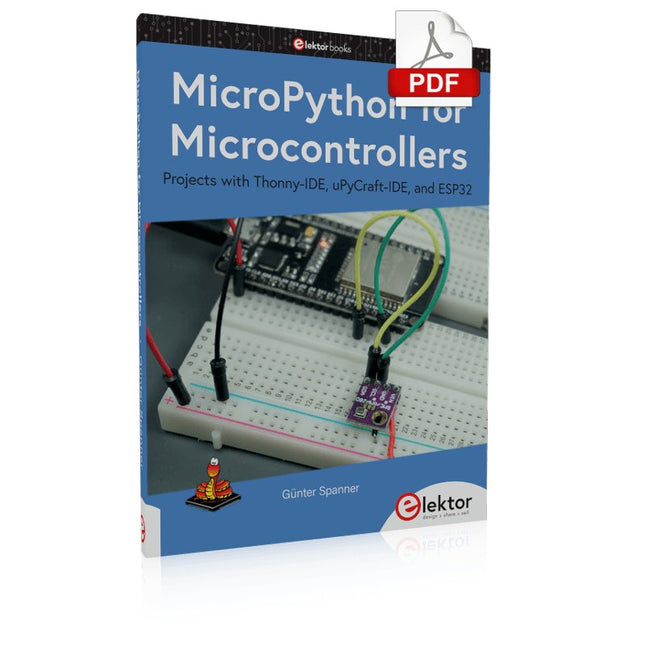
Projects with Thonny-IDE, uPyCraft-IDE, and ESP32
The 'Python' programming language has enjoyed an enormous upswing in recent years. Not least, various single-board systems such as the Raspberry Pi have contributed to its popularity. But Python has also found widespread use in other fields, such as artificial intelligence (AI) or machine learning (ML). It is obvious, therefore, to use Python or the 'MicroPython' variant for use in SoCs (Systems on Chip) as well.
Powerful controllers such as the ESP32 from Espressif Systems offer excellent performance as well as Wi-Fi and Bluetooth functionality at an affordable price. With these features, the Maker scene has been taken by storm. Compared to other controllers, the ESP32 has a significantly larger flash and SRAM memory, as well as a much higher CPU speed. Due to these characteristics, the chip is not only suitable for classic C applications, but also for programming with MicroPython.
This book introduces the application of modern one-chip systems. In addition to the technical background, the focus is on MicroPython itself. After the introduction to the language, the programming skills learned are immediately put into practice. The individual projects are suitable for use in the laboratory as well as for everyday applications. So, in addition to the actual learning effect, the focus is also on the joy of building complete and useful devices. By using laboratory breadboards, circuits of all kinds can be realized with little effort, turning the testing and debugging of the 100% homebrew projects into an instructive pleasure.
The various applications, such as weather stations, digital voltmeters, ultrasound range finders, RFID card readers or function generators, make the projects presented ideally suited for practical courses or subject and study work in the natural sciences, or in science and technology classes.
Specifications
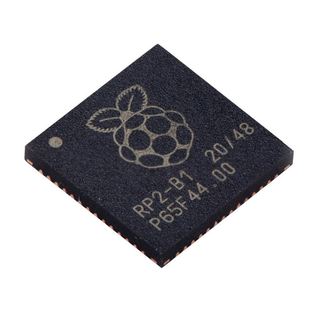
Dual ARM Cortex-M0+ @ 133 MHz
264 kB on-chip SRAM in six independent banks
Support for up to 16 MB of off-chip Flash memory via dedicated QSPI bus
DMA controller
Fully-connected AHB crossbar
Interpolator and integer divider peripherals
On-chip programmable LDO to generate core voltage
2x on-chip PLLs to generate USB and core clocks
30x GPIO pins, 4 of which can be used as analogue inputs
Peripherals
2x UARTs
2x SPI controllers
2x I²C controllers
16x PWM channels
USB 1.1 controller and PHY, with host and device support
8x PIO state machines
What you'll get
10x bare RP2040 chips
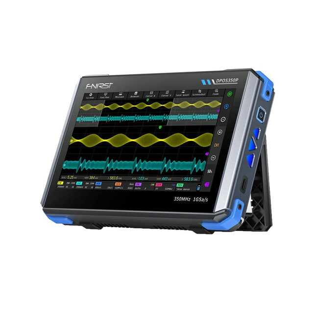
2 Channels • 350 MHz • 1 GSa/s • 50,000 wfm/s • 7 inch Touchscreen
The FNIRSI DPOS350P is a sleek 4-in-1 powerhouse in tablet form! This compact and portable device packs serious functionality: it combines a 2-channel oscilloscope (350 MHz), a signal generator (50 MHz), a frequency response analyzer (50 MHz), and a spectrum analyzer (200 kHz–350 MHz) – all in one unit.
Whether you're in R&D, troubleshooting, or field testing, the DPOS350P delivers the tools you need to measure, generate, analyze, and visualize electronic signals with precision and clarity. Its responsive high-resolution touchscreen and intuitive controls make signal analysis fast, flexible and efficient.
Features
Powerful Multi-Function Integration
350 MHz 2-channel oscilloscope with 1 GSa/s real-time sampling
50 MHz signal generator with 14 standard + custom waveforms
Spectrum analyzer (200 kHz–350 MHz): Perfect for EMI, RF & HF testing
Frequency response analyzer (FRA) up to 50 MHz
High-Performance Waveform Capture
50,000 wfm/s refresh rate for real-time signal clarity
350 MHz bandwidth (single-channel mode)
Detects rare and low-probability anomalies
Crisp Display & Smooth Operation
7" IPS touchscreen (1024 x 600 resolution)
Switch between grayscale and color temperature display
Easy to operate in various test environments
Reliable, Protected & Fast-Charging
High-voltage protection up to 400 V
Fast charging with QC 18 W (full charge in 2 hours)
Built for stable long-term operation
Data Storage & Export
Save up to 500 waveform records + 90 screenshots
USB export for easy reporting and offline analysis
Specifications
General
Display
7 inch (IPS full viewing angle)
Resolution
1024 x 600 pixels
Interaction mode
Capacitive touch screen
Total power consumption
10 W
Power-on configuration
5 presets
Charging
QC 18 W, 12 V/1.5 A (USB-C)
Battery
3.7 V, 8000 mAh lithium battery
Battery life
approx. 3 hours in operation, 5 hours standby
Heat dissipation
Air cooling
Expansion interface
USB data port
Automatic shutdown
15~60 minutes / off
Firmware upgrade
Support .iso image upgrade
Languages
English / Portuguese / Russian / Chinese
Dimensions
190 x 128 x 37 mm
Oscilloscope
Analog channels
2
Analog bandwidth
350 MHz
Rise time
1ns
Real-time sampling rate
1 GSa/s
Memory depth
60 Kpts
Input impedance
1 MΩ / 14PF
Time base range
5ns ~ 50s
Roll time base
50ms ~ 50s
Vertical sensitivity
2 mV ~ 20 V (1X)
Vertical range
16 mV ~ 160 V (1X)
DC accuracy
±2%
Time accuracy
±0.01%
Input coupling
DC / AC
Probe attenuation
1X / 10X / 100X
Hardware bandwidth limit
150M / 20M
High resolution mode
8bit ~ 16bit
Parameter measurements
12 types
Cursor measurement
Time, period, frequency, level, voltage
Trigger detection
Digital trigger
Trigger channel
CH1 / CH2
Trigger mode
Auto / Single / Normal
Trigger edge
Rising edge / Falling edge
Trigger suppression
L1 ~ L3
Trigger level
Manual / automatic 10% ~ 90%
Screenshot storage
90 pictures
Waveform storage
500 groups
Background grid
Display / hide
Waveform movement
Coarse adjustment / fine adjustment
Overvoltage protection
Withstand voltage 400 V
Waveform brightness
Adjustable
Simple FFT display
Yes
Digital fluorescence
Yes
Color temperature display
Yes
X-Y mode
Yes
ZOOM time base
Yes
One-key automatic adjustment
Yes
One-key return to zero
Yes
Data browser
Yes
Signal Generator
Waveform types
14 standard functions + captured waveform
Frequency
0~50 MHz (sine wave only, other waveforms up to 10M/5M/3M)
Amplitude
0~5 VPP
Offset
-2.5 V ~ +2.5V
Duty cycle
0.1~99.9%
Frequency resolution
1 Hz
Amplitude resolution
1 mV
Offset resolution
1 mV
Duty cycle resolution
0.1%
Customizable captured waveform
500 groups
Frequency Response Analyzer (FRA)
Excitation signal frequency
100 Hz ~ 50 MHz
Excitation signal amplitude
0~5 VPP
Excitation signal offset
-2.5V ~ +2.5V
Excitation frequency count
20~500
Cursor measurement
Frequency / gain / phase
Operating mode
Single / cyclic
System calibration
Yes
Spectrum Analyzer
Conversion method
FFT
FFT length
4K ~ 32K
Frequency range
200 KHz ~ 350 MHz
Level range
-60 dBmV ~ +260 dBmV
Cursor measurement
Frequency / amplitude
Marking parameter
Maximum energy harmonic
Waterfall chart
Yes
3D waterfall chart
Yes
Automatic adjustment
Yes
System calibration
Yes
Included
1x FNIRSI DPOS350P Oscilloscope (4-in-1)
2x 350 MHz Probes
1x QC 18 W Fast Charger (EU)
1x USB-C Cable
1x Alligator Clip
1x Storage Bag
1x Manual
Downloads
Manual
Firmware
AI Projects for the Raspberry Pi with the AI HAT+
Edge AI is transforming everyday devices by putting intelligence where it matters most: directly inside the hardware. With on-device inference, a camera can recognize a visitor instantly, a phone can translate speech without streaming audio to the cloud, and a wearable can detect anomalies in real time—fast, private, and reliable even when the network disappears.
This book is your practical guide to building exactly those kinds of systems with the Raspberry Pi AI HAT+ and the Hailo-8L accelerator. You’ll start with clear foundations: core AI and machine-learning concepts, how neural networks work, and what truly distinguishes Edge AI from cloud AI—plus an honest look at ethical considerations and future impacts.
Then it’s straight to hands-on physical computing. Step by step, you’ll set up Raspberry Pi OS, power and cooling, and develop in Python using the Thonny IDE. You’ll learn GPIO basics with lights and servos, mount the AI HAT+ hardware, install and verify the Hailo software stack, and connect the right camera—official modules or USB webcams, even multiple cameras.
From your first pipeline to real projects, you’ll run person detection, pose estimation, segmentation, and depth estimation, then level up with YOLO object detection: smart alerts, guest counters, and custom extensions. You’ll even connect vision to motion by combining gesture recognition with servo-driven mechanisms, including a robotic arm.
With troubleshooting tips, hardware essentials, and a practical Python refresher, this book turns Edge AI from buzzword into buildable reality.
Programmieren mit GNU Radio
HackRF ist eine Open-Source-Entwicklung von Great Scott Gadgets und dient als vielseitiges Frontend für Software Defined Radio (SDR). Mit HackRF One und dem Nachfolger HackRF Pro lassen sich eigene SDR-Anwendungen entwickeln, leistungsfähige Empfänger und Sender aufbauen sowie anspruchsvolle Aufgaben der HF-Messtechnik realisieren.
Dieses Buch eröffnet einen praxisnahen Einstieg in die Welt des Software Defined Radio. Schritt für Schritt zeigt der Autor, wie sich mit HackRF leistungsfähige SDR-Projekte umsetzen lassen – von den Grundlagen der HF-Technik bis hin zu anspruchsvollen Anwendungen mit GNU Radio.
Neben dem Umgang mit SDR Sharp (SDR#), RadioConda und GNU Radio vermittelt das Buch auch die Grundlagen moderner digitaler Signalverarbeitung. Zahlreiche Experimente und leicht nachvollziehbare Praxisbeispiele führen durch Themen wie AM-, FM- und SSB-Empfang, digitale Filter, Kurzwelle, Amateurfunk, Messsender und eigene HF-Projekte bis 6 GHz.
Ob Maker, Funkamateur, Elektronik-Enthusiast oder SDR-Einsteiger – dieses Buch vermittelt fundiertes Wissen, praxisnahe Anwendungen und die Motivation, die Möglichkeiten moderner SDR-Technik kreativ auszuschöpfen.
Programming with GNU Radio
HackRF is an open-source hardware platform developed by Great Scott Gadgets and serves as a versatile front end for software-defined radio (SDR). With HackRF One and its successor, HackRF Pro, users can develop their own SDR applications, build powerful receivers and transmitters, and tackle demanding RF measurement tasks.
This book provides a practical introduction to the world of SDR. Step by step, the author shows how powerful SDR projects can be implemented with HackRF – from the fundamentals of RF technology to advanced applications using GNU Radio.
In addition to working with SDR Sharp (SDR#), RadioConda, and GNU Radio, the book also covers the fundamentals of modern digital signal processing. Numerous experiments and easy-to-follow practical examples guide readers through topics such as AM, FM, and SSB reception, digital filters, shortwave radio, amateur radio, signal generators, and custom RF projects up to 6 GHz.
Whether you are a maker, radio amateur, electronics enthusiast, or SDR beginner, this book provides solid knowledge, practical applications, and the motivation to creatively explore the possibilities of modern SDR technology.
High-Performance LoRa Communication Device
The Elecrow ThinkNode M5 is a compact, portable LoRa communication device designed for off-grid messaging, location sharing, and outdoor use. Powered by an ESP32-S3 processor and an SX1262 LoRa chip, it comes pre-installed with Meshtastic firmware and can be configured conveniently via Bluetooth using the official Meshtastic app.
The integrated multi-GNSS module supports GPS, GLONASS, BeiDou, and QZSS for reliable positioning and location sharing. Messages and device information are displayed on the energy-efficient 1.54-inch e-paper screen, while the built-in 1,200 mAh rechargeable battery enables extended mobile operation.
With its integrated LoRa antenna, compact housing, RTC, and support for both Meshtastic and MeshCore firmware, the ThinkNode M5 is a practical communication solution for hiking, camping, remote locations, and emergency situations where conventional mobile networks are unavailable.
Features
LoRa communication
Multi-GNSS positioning
1,200 mAh rechargeable battery
1.54-inch e-paper display
Built-in RTC
Compatible with MeshCore
Compatible with Meshtastic
Specifications
Main Processor (ESP32-S3)
CPU/SoC
Xtensa 32-bit LX7 dual-core processor, clocked at up to 240 MHz
System Memory
512 KB SRAM, 8 MB PSRAM
Storage
4 MB Flash, 384 KB ROM
Firmware
Meshtastic firmware is fully compatible, and the signal is transmitted in LoRa mode
EPD (Electronic Paper Display)
Display Size
1.54 inch EPD (monochrome Ink screen)
Display Materials
E-lnk (Electronic Ink)
Resolution
200 x 200
Driver Chip
SSD1681 (via SPI or I²C interface)
Global Fresh Time
2s
Wireless Communication
Bluetooth
Bluetooth Low Energy and Bluetooth 5.0 (phone configuration)
LoRa
SX1262 LoRa Module, EU 868 MHz(external antenna)
Hardware
Interfaces
USB-C, RP-SMA
Function
GPS Location (GPS, GLONASS, BeiDou, QZSS), EPD Display, RTC, USB 2.0, PMU power management (built-in 1200 mAh lithium battery), buzzer, etc.
Button
Knob Switch, Function Button, Page Turn Button, GPS Switch, Reset Button
LED Indicator
Power supply, GPS/LoRa indication
Others
Power Input
5 V/1 A, supports USB or lithium battery power supply
Power consumption
The maximum working current is about 340 mA (CPU + LoRa module), and the low power consumption is about 34 uA
Operating Temperature
-10~50°C
Storage Temperature
-20~60°C
Relative humidity
10-95%, @ 40°C (non-condensing)
Enclosure
ABS Plastic
Dimensions
82 x 51.6 x 26.3 mm
Weight
81 g
Included
1x Elecrow ThinkNode M5
1x LoRa antenna
1x USB-C cable
1x Manual
Downloads
Manual
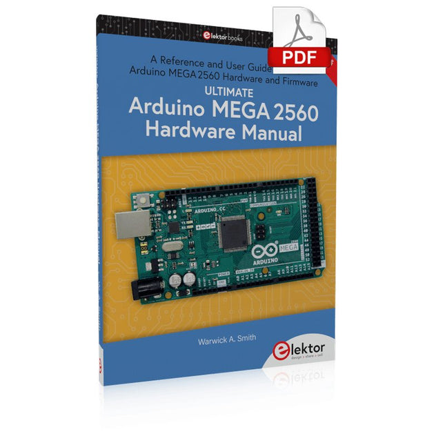
A Reference and User Guide for the Arduino Mega 2560 Hardware and Firmware
A manual providing up-to-date hardware information for the Arduino Mega 2560.
The Arduino Mega 2560 is an upgrade to the popular Arduino Uno board, providing more pins, serial ports and memory. Arduino is the easy to use open-source electronics platform used by hobbyists, makers, hackers, experimenters, educators and professionals.
Get all the information that you need on the hardware and firmware found on Arduino Mega 2560 boards in this handy reference and user guide. Ideal for the workbench or desktop. This manual covers the Arduino Mega 2560 hardware and firmware, and is a companion volume to the Ultimate Arduino Uno Hardware Manual, which covers the Arduino Uno hardware and firmware.
Contains all of the Arduino Mega 2560 hardware information in one place
Covers Arduino / Genuino Mega 2560 revision 3 and earlier boards
Easily find hardware technical specifications with explanations
Pin reference chapter with interfacing examples
Diagrams and illustrations for easy reference to pin functions and hardware connections
Learn to back up and restore firmware on the board, or load new firmware
Basic fault finding and repair procedures for Arduino Mega 2560 boards
Power supply circuits simplified and explained
Mechanical dimensions split into five easy to reference diagrams
Contains circuit diagrams, parts list and board layout to easily locate components
A chapter on shield compatibility explains how shields work across different Arduino boards
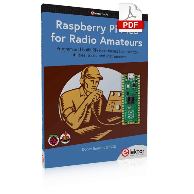
Program and build RPi Pico-based ham station utilities, tools, and instruments
Although much classical HF and mobile equipment is still in use by large numbers of amateurs, the use of computers and digital techniques has now become very popular among amateur radio operators. Nowadays, anyone can purchase a €5 Raspberry Pi Pico microcontroller board and develop many amateur radio projects using the “Pico” and some external components. This book is aimed at amateur radio enthusiasts, Electronic Engineering students, and anyone interested in learning to use the Raspberry Pi Pico to shape their electronic projects. The book is suitable for beginners in electronics as well as for those with wide experience.
Step-by-step installation of the MicroPython programming environment is described. Some knowledge of the Python programming language is helpful to be able to comprehend and modify the projects given in the book. The book introduces the Raspberry Pi Pico and gives examples of many general-purpose, software-only projects that familiarize the reader with the Python programming language. In addition to the software-only projects tailored to the amateur radio operator, Chapter 6 in particular presents over 36 hardware-based projects for “hams”, including:
Station mains power on/off control
Radio station clock
GPS based station geographical coordinates
Radio station temperature and humidity
Various waveform generation methods using software and hardware (DDS)
Frequency counter
Voltmeter / ammeter / ohmmeter / capacitance meter
RF meter and RF attenuators
Morse code exercisers
RadioStation Click board
Raspberry Pi Pico based FM radio
Using Bluetooth and Wi-Fi with Raspberry Pi Pico
Radio station security with RFID
Audio amplifier module with rotary encoder volume control
Morse decoder
Using the FS1000A TX-RX modules to communicate with Arduino
This bundle gives you everything you need to get started right away with the XIAO ESP32-C3 development board. Learn the fundamentals of the ESP32-C3 and build practical projects with Wi-Fi, Bluetooth, sensors, displays, PWM, Deep Sleep, and much more.
Book: Build Smart Projects with the XIAO ESP32-C3 Board
The XIAO ESP32-C3 board combines the ultra-compact form factor of the XIAO series with the full capabilities of the ESP32-C3 chip, including integrated Wi-Fi and Bluetooth 5.0. This book is a comprehensive, hands-on guide to getting the most out of this powerful yet affordable development board.
The author takes readers from the fundamentals to advanced projects. Starting with LED blinking and dimming, the book progresses to ADC and PWM for precise sensor interfacing and PWM-controlled lighting effects before moving on to building practical, real-world applications, including:
A Wi-Fi weather station with an OLED display and real-time online weather data
An ultrasonic parking assistant with audible feedback
A refrigerator monitoring probe with climate sensing and Deep Sleep for years of battery operation
A retro Pong game controlled by a touch-free sensor
A microphone-based party app that responds to claps
And much more: lighting control, reaction-time measurement, mains frequency analysis, soil moisture sensing, ambient LED lighting, and 7-segment displays
Seeed Studio XIAO ESP32C3
Seeed Studio XIAO ESP32C3 has equipped a highly-integrated ESP32-C3 chip, built around a 32-bit RISC-V chip processor with a four-stage pipeline that operates at up to 160 MHz.
The board equips highly-integrated ESP32-C3 SoC. The chip has been installed with a complete 2.4 GHz Wi-Fi subsystem which means it supports Station mode, SoftAP mode, SoftAP & Station mode, and promiscuous mode for multiple Wi-Fi applications. It works under an ultra-low power state, also supporting features of Bluetooth 5 and Bluetooth mesh. There are 400 KB SRAM & 4 MB Flash on the chip, allowing for more programming space, and bringing more possibilities to the IoT control scenarios.
Applications
Internet of Things
Wearable devices
Health monitoring
Education
Low-Power networking
Rapid prototyping
Specifications
Processor
ESP32-C3 SoC
RISC-V single-core 32-bit chip processor with a four-stage pipeline that operates at up to 160 MHz
Wireless
Complete 2.4GHz Wi-Fi subsystem
Bluetooth Low Energy 5.0/ Bluetooth Mesh
On-chip Memory
400 KB SRAM & 4 MB Flash
Interface
1x UART, 1x I²C, 1x SPI, 11x GPIO (PWM), 4x ADC
1x Reset button, 1x Boot button
Power (Typ.)
Max 3.3 V Output Current: 500 mA Test Condition: BAT Pin Input @ 3.8 V Source Capability: 3 A
Charging current: 380 mA(Fast) / 40 mA(Trickle)
Input voltage (VIN): 5 VInput voltage (BAT): 3.7 V
Deep Sleep Power Consumption
Deep Sleep Mode: 44 μA
Wi-Fi Enabled Power Consumption
Active Mode: 75 mA
Modem-sleep Mode: 25 mA
Light-sleep Mode: 4 mA
BLE Enabled Power Consumption
Modem-sleep Mode: 27 mA
Light-sleep Mode: 10 mA
Dimensions
21 x 17.8 mm
Included
1x Seeed Studio XIAO ESP32C3
1x Antenna
2x 7-pin header
Downloads
Wiki
Datasheet
This bundle contains:
Book: Build Smart Projects with the XIAO ESP32-C3 Board (normal price: €35)
Board: Seeed Studio XIAO ESP32C3 (normal price: €10)
Vom Messwert zur stabilen Entscheidung
Wie wird aus einem einfachen Mikrocontroller ein intelligentes System, das Sensorwerte erfasst, verarbeitet und sinnvoll darauf reagiert? Dieses Buch zeigt es Ihnen Schritt für Schritt – verständlich, praxisnah und ohne unnötige Vorkenntnisse.
Sie beginnen mit den Grundlagen der digitalen und analogen Ein- und Ausgänge. Anschließend lernen Sie, wie Sensorwerte gelesen, geglättet und zuverlässig bewertet werden. Anschauliche Beispiele erklären, warum einzelne Messwerte oft täuschen können und wie Mittelwertbildung, Hysterese und einfache Entscheidungsregeln für stabile Ergebnisse sorgen. Nach und nach erweitern Sie Ihre Projekte um Displays, I²C-Kommunikation und mehrere vernetzte Mikrocontroller. So entstehen verteilte Systeme, in denen Raspberry Pi Pico und ATtiny-Controller Daten austauschen und gemeinsam Aufgaben übernehmen.
Im fortgeschrittenen Teil erhalten Sie einen leicht verständlichen Einstieg in Merkmalsbildung, Datenvorverarbeitung, hybride Entscheidungsmodelle und TinyML-nahe Anwendungen. Dabei verbinden Sie klassische Regelungstechnik mit modernen datenbasierten Methoden.
Alle Projekte werden von ausführlich kommentierten Programmen in C und MicroPython begleitet. Das Buch richtet sich an Einsteiger, Maker, Studierende und alle, die Embedded-Systeme von Grund auf verstehen möchten.
Am Ende können Sie eigene Systeme entwickeln, die nicht nur messen, sondern Informationen auswerten, zuverlässige Entscheidungen treffen und gezielt reagieren.
Open-Source-Code mit Arduino IDE und PlatformIO
Autonomes Fahren: GPS, Accelerometer, Gyroskop
PS3-Controller
Mikrocontroller wie der Arduino und Einplatinenrechner wie der Raspberry Pi haben sich zu beliebten Komponenten entwickelt. Dritter im Bunde ist der ESP32 der Firma Espressif. Mikrocontroller dieser Baureihe zeichnen sich durch eine Vielzahl implementierter Funktionen aus, die bei einem Arduino konventioneller Prägung mit einem Atmel-AVR-Mikrocontroller erst mit weiterer Hardware möglich sind. Prominentes Beispiel sind hier die WiFi- und Bluetooth-Funktionalitäten. Gegenüber einem Raspberry Pi zeichnen sie sich durch einen deutlich geringeren Preis aus.
Allgemeine Informationen für die Realisierung eines Roboterauto-Projekts mit dem ESP32 sind leicht zu finden. Dabei handelt es sich aber oft nur um Ausführungen zu einem Teilaspekt, ohne inhaltliche oder funktionale Abstimmung. So ist nicht nur die Beschaffung der benötigten Informationen mühselig und zeitaufwändig, sie kann auch außerordentlich fehlerträchtig sein.
Ansatzpunkt dieses Buches ist, diese Lücke zu schließen. Es geht auf verschiedene Möglichkeiten eines Chassis ein, vermittelt nötige Kenntnisse und führt schrittweise von einer einfachen Motorsteuerung zu einem komplexen sensor- und sprachgesteuerten Roboterauto. Hacks rund um GPS und eine PlayStation 3 runden die Sache ab.
Inhalt
Bei der Reihenfolge der Kapitel wurde versucht – beginnend bei der Darstellung von grundlegenden Informationen – über die Lösung einfacher Aufgaben zu etwas anspruchsvolleren Techniken zu führen.
Der Mikrocontroller ESP32
Die Software erstellen
Die Stromversorgung
Rund um die Hardware
Das Chassis
Der Gleichstrommotor
Kabellose Steuerung über WiFi
Mit Sensoren Hindernisse erkennen
Eine eigene Roboterauto-App
Servo und Lichtsensor
GPS
Accelerometer / Gyroskop
PS3-Controller
Roboterauto-App
Hinweis zur Software
Die Dateien haben das Suffix (.cpp). Grund ist die Entwicklung mit PlatformIO. Mit Copy & Paste sollten sie auch in der Arduino-IDE verwendet werden können.