
Search results for "raspi OR buffer OR 150719 OR 1"
-

Elektor Digital Elektor Circuit Special 2025 (PDF) FR
Le téléchargement intégral de ce numéro est disponible pour nos membres GOLD et GREEN sur le site Elektor Magazine ! Pas encore membre ? Cliquez ici. adaptateur de mesure USBTest du courant et des signaux des ports USB sortie boucle de courant 4-20 mA pour Arduino UnoUne interface de boucle de courant fiable et insensible aux interférences électromagnétiques commande automatique pour aspirateurGardez votre établi propre générateur DDS avec ATtiny testeur d'ampli-op V2Nouveau circuit imprimé – désormais compatible avec les CMS amplificateur audio à tube 550 mWson chaleureux des tubes à vide surveillance des fusiblesavec une LED clignotante préamplificateur RIAA HQExploitez tout le potentiel sonore de vos disques vinyles ! Outil de réglage pour platines vinylesGénérateur de lumière stroboscopique 100–120 Hz basé sur Arduino Elektor Classics : ampli vidéo gradateur à télécommande infrarougeContrôlez votre éclairage avec confort et précision comment utiliser switch…case avec des chaînes de caractères en C++/EDI Arduino détecteur d’aimantsAvec un simple capteur à effet Hall bouton de mise sous tension intelligent pour Raspberry PiUne solution pour Raspberry Pi jusqu’au modèle 4 astuces clés pour makersDes conseils pros pour vos projets projets pratiques avec le timer 555Commande de moteur CC et jeux de rapidité moniteur de charge CA simpleÉconomisez de l'énergie grâce à un appareil simple batteries externes en parallèleTrois jours d’autonomie VFO jusqu’à 15 MHzRéalisation avec un Raspberry Pi Pico accordeur de violon avec ATtiny202 Elektor Classics : ampli vidéo pour TV N&B capacimètre20 pF à 600 nF horloge quasi analogique Mk IIDeux anneaux LED pour les heures et les minutes concevez sans limites(grâce à l’écosystème complet d’Arduino) dé à lampes néon Elektor Classics : indicateur d'accord RTTY solutions matérielles inspirantes pour vos projets ESP Elektor Classics : alimentation 3 A LED RGB avec circuit de commande intégréLumière de précision : les ICLED établissent de nouvelles normes expérience : un Thérémine analogico-numérique ?Combiner des capteurs numériques modernes avec l’intemporel générateur analogique XR2206 carte émetteur-récepteur audio ESP32 (1)Démo : lecture de fichiers WAV depuis une carte SD infographies : Circuits et conception de circuits 2025 petit mixeur audioUne conception polyvalente et modulable minuteur intelligent pour éclairage d’escalierÉconomisez encore plus sur votre facture d’énergie ! modernisez vos voletsContrôlez les systèmes Velux avec un ESP32 et MQTT chauffe-pieds à transistorsConfort économe en énergie le quadricoptère M5Stamp Fly est-il le prochain drone Tello ? (Revue) optimiser la portée Wi-Fi de l’ESP32-C3 SuperMiniUne modification d’antenne simple et efficace station de soudage à air chaud ZD-8968Un outil de travail économique ou uniquement de l'air chaud ? testeur de radar de reculDétecter les pannes du système d’aide au stationnement d’un véhicule
€ 10,95
-

Elektor 05-06/2025 (DE)
Diese Ausgabe steht allen GOLD- und GREEN-Mitgliedern auf der ElektorMagazine-Website zum Download bereit! Sie sind noch kein Mitglied? Hier klicken! PbMonitor v1.0Ein Batterieüberwachungssystem für USV und Energiespeicher Solarladeregler mit MPP-TrackingTeil 1: Grundlagen eines Solarreglers für Insel-Anlagen B-Feld-Integrationsmagnetometer mit selbstgebauten Sensoren Präzise, richtig oder genau?Ihre Messgeräte müssen alles sein! AD7124 – Ein Präzisions-ADC in der PraxisHinweise für die Sensor-Signalaufbereitung PID-RegelungswerkzeugOptimieren Sie ganz einfach Ihre Parameter embedded world 2025 Aller Anfang ......muss nicht schwer sein: Klangeinstellung! Academy Pro BoxBook + Online Course + Hardware Milliohmmeter-AdapterNutzen Sie die Präzision Ihres Multimeters! Der nächste Meilenstein bei HalbleiternWeiter in Richtung 1,4 nm Steckverbinder in DurchstecktechnikDas Beste aus zwei Welten: THR FrequenzzählerPortabel und mit automatischer GPS-Kalibrierung Analoge MessgeräteBemerkenswerte Bauteile Stand-alone-QuarztesterWie genau ist Ihre Taktquelle? Preiswerter I²C-TesterSchließen Sie I²C-Chips direkt an Ihren PC an Aus dem Leben gegriffenWer das Kleine nicht ehrt... 2025: Eine Odyssee in die KIDie transformativen Auswirkungen auf die Softwareentwicklung Projekt 2.0Korrekturen, Updates und Leserbriefe Standalone-MIDI-Synthesizer mit Raspberry PiTeil 2: Setup mit Intelligenz aufwerten Nortonisierter Wien-Brücken-OszillatorKleine Änderungen führen zu bedeutenden Verbesserungen 10-Cent-Controller in der PraxisRISC-V-Mikrocontroller CH32V003 und MounRiver Studio ausprobiert Audio-Player mit FPGA und EqualizerTeil 2: Lautstärkeregelung, erweitertes Mischen und ein Web-Interface
€ 14,90
-

Elektor Mai/Juin 2025 (FR)
Le téléchargement intégral de ce numéro est disponible pour nos membres GOLD et GREEN sur le site Elektor Magazine ! Pas encore membre ? Cliquez ici. PbMonitor v1.0Un système de surveillance des batteries pour les applications à onduleurs et de stockage d'énergie contrôleur de charge solaire avec MPPT (1)Principes de base d'un contrôleur de charge solaire pour les systèmes autonomes magnétomètre à intégration du champ et capteurs artisanaux exactitude, ou précision ?vos appareils doivent posséder les deux ! AD7124 : un C/AN de précision en pratiqueFeatures for Sensor Signal Conditioning outil de contrôle PIDOptimisez facilement vos paramètres embedded world 2025 démarrer en électronique...…contrôle de la tonalité Academy Pro BoxLivre + cours en ligne + matériel adaptateur Milliohm-mètreUtilisant la précision de votre multimètre Un nouveau jalon dans le domaine des semi-conducteursEn route vers le 1,4 nm Connecteurs à technologie traversanteLe meilleur des deux mondes : THR fréquencemètrePortable et auto-calibré par GPS compteurs analogiquesDrôles de composants, la série testeur de quartz autonomeQuelle est la précision de votre source d'horloge ? testeur I²C peu couteuxconnecter des appareils I²C directement à votre PC sur le vifbienvenue chez les Pt’tites 2025 : une odyssée de l'IAL'impact transformateur sur le développement de logiciels projet 2.0Corrections, mises à jour, et courrier des lecteurs synthétiseur MIDI autonome Raspberry Pi (2)Améliorons notre configuration avec l’Intelligence oscillateur à pont de Wien "nortonisé"Petite cause, grand effet tester un microcontrôleur à 0,10 $Le microcontrôleur CH32V003 RISC-V et MounRiver Studio en pratique un lecteur audio avec égaliseur basé sur un FPGA (2)Ajout d'un réglage du volume, d'un mixage avancé et d'une interface Web
€ 15,50
-

Arduino Official Arduino USB-C Cable (2-in-1)
Now you can connect your Arduino boards with the official Arduino USB cable. Through a USB-C to USB-C with a USB-A adapter connection, this data USB cable can easily connect your Arduino boards with your chosen programming device. The Arduino USB cable has a nylon braided jacket in the typical Arduino colors white and teal. The connectors have an aluminum shell that protects your cable from harm at the same time as looking cool. Length: 100 cm Aluminium shell with logo Nylon braided jacket white and teal
€ 12,95
Members: € 11,66
-

Elektor September/Oktober 2025 (NL)
Elektor GREEN en GOLD leden kunnen deze uitgave hier downloaden. Nog geen lid? Klik hier om een lidmaatschap af te sluiten. ESP32 Audio Transceiver Board (Deel 2)Draadloze audio-overdracht Inductieve AM-zenderGebruikt Pico's PIO in een Arduino-sketch Navigeren door draadloze protocollen navigerenEen technische gids Satelliettracking met behulp van LoRaHet TinyGS-netwerk brengt gegevens uit de ruimte naar de aarde. 4G-Compatibele SMS afstandsbedieningBedien je apparatuur op afstand Hogesnelheids-probeIngangen met hoge impedantie voor signalen tot 200 MHz Uit het leven gegrepenKafka KrakenSDR Prestatietests met de RP2350Is een upgrade van Raspberry Pi Pico 1 naar versie 2 de moeite waard? Contactloze E-veldmetingen (2)Een laservibrometer voor het beoordelen van de trillingen van het membraan Kristallen en oscillatorenVerbetering van de kristalnauwkeurigheid door gerichte keuze van condensatoren Alle begin......gaat audio! Zelf firmware coderen voor embedded projecten SPECTRAN® V6 MobileModulaire, configureerbare realtime-spectrumanalyzer voor betrouwbare metingen over alle frequentiebereiken De toekomst van AI wordt gesmeed in siliciumEen interview met Anastasiia Nosova Autonome Sensor-Node v2.0 (Systeemarchitectuur)Zonne-energieplatform met geïntegreerde GPS, LoRaWAN en meer Precieze positioneringBluetooth channel sounding getest Testgestuurd ontwikkelen bij het schrijven van firmware Telefoon gestuurde modelautoWi-Fi + ESP32 + Smartphone = Afstandsbediening 2025: Een AI-odysseeAI-redeneermodellen: De gedachtegang-revolutie Zonne-laadregelaar met MPP-tracking (3)Software en Inbedrijfstelling Raspberry Pi Zero Web Streaming CameraDe ZeroTier VPN gebruiken Beste soldeerder van de Beneluxvakmanschap in de schijnwerpers Seminaroverzicht Electronics & ApplicationsLeer, ontdek en netwerk op E&A 2025 Eurocircuits at E&A 2025 E&A gadget 2025: racen over de beursvloer met slimme printplaat op wielenVijf vragen aan Casper van Doorne, ontwerper van de beursgadget Beursgadget E&A bekendontwerp en bestuur je eigen raceauto Vakbeurs E&A is het elektronicaparadijs van de Benelux“Techneuten blijven kinderen” Rohde & SchwarzPioneering Innovation in Test & Measurement Diederik Jekel opent Electronics & Applications
€ 15,95
-

JOY-iT JOY-iT PS1440-C-Pro Programmable Laboratory Power Supply with RS485 (1440 W)
With the JOY-iT PS1440-C-Pro, you get a programmable laboratory power supply that delivers DC voltages ranging from 0.01 to 60 V and DC currents from 0.01 to 24 A at the voltage output. The intuitive control panel allows you to program, store, and recall up to 9 different DC voltage settings. You can also configure individual protection and limiting functions—such as overvoltage protection. All settings are easily adjusted via the keypad and/or rotary control and are clearly shown on the high-resolution 2.4" color display. For enhanced connectivity, the PS1440-C-Pro includes an RS485 interface for robust, long-distance communication. This makes it ideal for complex setups where signal stability, noise immunity, and reliable data transfer are critical. The included connector ensures a secure connection, improving the overall reliability and performance of your laboratory equipment setup. Features Complete device ready for immediate use RS485 interface Battery charging function Values can be entered conveniently via keypad Over current & over voltage protection adjustable Integrated RTC, NTC temperature sensor Included detailed documentation in English, German & French Specifications Input voltage 230 V Output voltage 060 V Output current 0-24 A Output power 0-1440 W Input voltage accuracy ±1% +5 digits Output voltage accuracy ±0.3% +3 digits Output current accuracy ±0.5% +5 digits Battery voltage ±0.5% +3 digits Input voltage measurement resolution 0.01 V Output voltage measurement resolution 0.01 V Current measurement resolution 0.01 V Battery voltage measurement resolution 0.01 V Response time in constant voltage mode 2 ms @ 0.1-5 A Load regulation in constant voltage mode ±0.1% +2 digits Load regulation in constant current mode ±0.1% +3 digits Measuring range electric charge 0-9999.99 Ah Measuring range energy 0-9999.99 Wh Statistical errors in electric charge & energy ±2% Output ripple 100 mV VPP @ 12 V150 mV VPP @ 24 V Sensor temperature detection range −10~100°C (0-200°F) Sensor temperature detection accuracy ±3°C (±6°F) Working mode Step-down operation Screen brightness setting Level 0-5, 6 levels in total Permissible working temperature −10~40°C (0-104°F) Dimensions 170 x 93 x 340 mm Included JOY-iT PS1440-C Power Supply 2-pin connector for RS485 interface Power cord Manual Downloads Datasheet MODBUS Protocol PC Software Driver for Windows
€ 499,00
Members: € 449,10
-

Elektor Digital Elektor Maart/April 2026 (PDF) NL
Elektor GREEN en GOLD leden kunnen deze uitgave hier downloaden. Nog geen lid? Klik hier om een lidmaatschap af te sluiten. PIO programmeren op de Raspberry Pi PicoNegen instructies, veel mogelijkheden AI buiten de browser brengenAI-CLI's gebruiken voor het coderen, compileren en valideren van embedded projecten De Scrutiny DebuggerDebuggen, visualiseren en testen van code in Embedded C/C++ Sigfox breakout board (1)Een zelfgebouwde radio BoB Low-Noise voeding (2)Constructie, montage en praktische implementatie Eenvoudige signaalgenerator met de RP2040Analoge en digitale signalen voor ongeveer €10 De toekomst van slimme huizen verkennen met Matter en Edge AIBieden de nieuwste updates van Matter en de opkomst van Edge AI technici eindelijk de tools om de intelligente, slimme huizen te bouwen die gebruikers zijn beloofd? Differentiële druksensorenVoorspellend onderhoud in HVAC-systemen Security by designTechnische basisprincipes beperken storingen Embedded security is niet langer optioneel CRA en PQC herzien prioriteiten voor embedded securityWaarom zelfs kleine IoT- en industriële bedrijven een upgradeplan nodig hebben embedded world 2026Een interview met Benedikt Weyerer, Executive Director embedded world Praktijkervaring met I3CGebruik van hardware van ST en Microchip Het BLEnky-projectSnelle prototyping voor Bluetooth Low Energy toepassingen Pulsbreedtemodulatievan een eenvoudige aan/uit-thermostaat naar een rimpelloos DC-signaal AudiotronicaOorstrelende elektronica voor zelfbouw Uit het leven gegrepenRead the f...ing manual! ESP32 audio transceiver board (Deel 4)Afstemmen van de kloksignalen en een bekabelde versie 2026: An AI OdysseyDe kater van Vibe-Coding in 2025 Symmetrische DC-belastingStatische of dynamische en symmetrische gelijkstroombelasting Gezichten tellen met MaixCAMEen eenvoudige methode om de omvang van het publiek vast te leggen
€ 9,95
-

Rigol Rigol RSA3015E-TG Real-time Spectrum Analyzer (9 kHz – 1.5 GHz)
Highlights Frequency: 1.5 GHz DANL: -161 dBm Phase Noise: -102 dBc/Hz RBW: 1 Hz Specifications Ultra-Real technology Frequency: up to 1.5 GHz Displayed average noise level (DANL): <-161 dBm (typical) Phase noise: <-102 dBc/Hz (typical) Level measurement uncertainty: <1.0 dB 1.5 GHz tracking generator Min. RBW 1 Hz Up to 10 MHz real-time analysis bandwidth Multiple measurement modes Various advanced measurement functions EMI measurement application (option) Multiple trigger modes and trigger masks Density, spectrogram, and other display modes PC software options 10.1'' capacitive multi-touch screen; supporting touch gestures USB, LAN, HDMI and other communication and display interfaces Included 1x Rigol RSA3015E-TG Spectrum Analyzer 1x Power cord 1x USB cable
€ 2.176,79
-

Elektor Labs Elektor Low-Noise Lab Power Supply
The Elektor Low-Noise Lab Power Supply is a fully analogue, adjustable, medium-power symmetrical bench supply that contains no switching or digital components. It provides an output voltage adjustable between 0 V and ±22 V, and an output current adjustable from 0 A to 1 A. Because it avoids any form of switching circuitry, the design delivers extremely low noise. To display both output voltages and currents, four miniature moving-coil panel meters are used. Most modern laboratory power supplies and AC adapters employ switch-mode techniques. Even the best examples inevitably exhibit high-frequency ripple and other switching artefacts on their output, which can interfere with the testing of sensitive analogue circuits and disturb low-level measurements. To overcome this, the concept here is a completely analogue power supply. Although less efficient than its switch-mode counterparts, the reduced efficiency is of little importance for test-bench use and ensures cleaner, more reliable measurement results. Because many analogue circuits require a symmetrical supply, this design delivers positive and negative output voltages of equal magnitude. A small amount of adjustment is available to compensate for any imbalance. Naturally, a variable current-limit function is also included. The kit includes the components required to build the power supply, except for the transformers. Specifications Output Voltage 0…+22 V, 0, −22 V Output Current 0…+1 A, 0…−1 A Noise −85 dBV, (at 0.95 A/20 V, B = 22 kHz) −84 dBV (at 0.95 A/20 V, B > 500 kHz) Ripple 50 µVRMS (at 950 mA/20 V, B = 22 kHz, mainly 100 Hz component) Included 3x PCBs: Regulator (PCB-1), Mains Filter (PCB-2) and Transformer (PCB-3) All the components except the AC transformers 4x moving-coil meters Additional parts for wiring (wires, banana sockets, IEC Power entry module, etc.) Not included The three AC transformers An enclosure Parts List For the Regulator PCB (240386-1) Resistors (250 mW, 1%) R1 = 12 Ω R2, R8, R37, R62 = 1 MΩ R3, R7, R10, R13, R17, R20, R22, R30, R35, R42, R45, R47, R55, R60 = 100 Ω, 600 mW R4, R5 = 4.7 kΩ R6 = 100 kΩ R9, R12, R14, R36, R38, R39, R61, R63, R66, R72, R78, R79 = 10.0 kΩ, 600 mW R11 = 9.76 kΩ, 600 mW R15, R40 = 44.2 kΩ, 600 mW R16, R41, R77 = 1 kΩ R18, R43 = 1.5 kΩ, 1 W, 5% R19, R44 = 470 Ω, 1 W, 5% R21, R46 = 330 Ω, 600 mW R23, R24, R48, R49 = 1.0 Ω, 1 W R25, R50 = 1 kΩ, 1 W, 5% R26, R28, R51, R53 = 1.000 kΩ 0.1%, 15 ppm/C R27, R29, R52, R54 = 10.00 kΩ 0.1%, 15 ppm/C R31, R56 = 1.2 kΩ, 1 W, 5% R32, R57 = 47 kΩ R33, R58 = 270 Ω R34, R59 = 27 kΩ R64, R69 = 12.0 kΩ R65 = 3.0 kΩ, 600 mW R67, R80 = 470 Ω, 600 mW R68, R70 = 6.8 kΩ, 600 mW R71 = 30.0 kΩ,, 600 mW R73, R74, R75, R76 = 10 MΩ P1, P2, P3 = 10 kΩ, 200 mW, 20%, potentiometer, 1 turns, single, lin., panel mount P4, P5 = 500 Ω, 500 mW, 10%, trimmer, 25 turns, 3296Y-1-501LF Bourns P6, P7 = 10 kΩ, 500 mW, 10%, trimmer, 25 turns, 3296Y-1-501LF Bourns Capacitors C1 = 100 nF, 50 V, 10%, ceramic X7R, LS 5 mm C2, C3, C6, C7, C30 = 10 µF, 63V, 20%, LS 2.5 mm, 3000hours@105°C C4, C5, C8, C9, C13, C14, C18, C19, C23, C24, C28, C29, C31, C32, C38, C39 = 100 nF, 250 V, 10%, PET, LS 7.5 mm C10, C20 = 47 nF, 100 V, 5%, PET, LS 5 mm C11, C21 = 10 nF, 100 V, 5%, PET, LS 5 mm C12, C22 = 220 µF, 35 V, 20%, 0.024 Ω, LS2.5/3.5 mm, Ir 3.4 A, 2000hours@125°C, polymer C15, C25 = 120 µF, 50 V, 20%, ESR 0.02 Ω, Diam. 10 mm max., LS 5 mm C16, C26 = 15 nF, 100 V, 5%, PET, LS 5 mm C17, C27 = 47 nF, 100 V, 5%, PET, LS 5 mm C33, C34 = 22 µF, 50 V, 20%, LS 2 mm, 10000 hours @ 105°C C35, C36, C44, C45 = 1 µF, 100 V, 10%, LS 5 mm, ceramic X7R C37 = 100 uF, 50 V, 20%. LS 3.5 mm C40, C41, C42, C43, C46, C47, C48, C49 = 1000 µF, 50 V, 20%, LS 5/7.5 mm, Ir 3.32 A, 10000hours@105°C, D 16 mm C50, C51, C52, C53 = 47 nF, 100 V, 10%, ceramic X7R, LS 5 mm Inductors L1, L2 = 4.7 µH, 3.2 A, 0.033 Ω, LS 5 mm, RLB0914-4R7ML Bourns L3 = Commom mode choke, 14.5 mH, 3 A, SSRH24NH-30145 Kemet Semiconductors D1, D2, D3, D4, D5, D9, D10, D11, D15 = BAT85, DO-34 D6, D7, D12, D13 = SR560, DO-201AD D8, D14, D16 = 1N4148, DO-35 D17 = Zenerdiode, 5.6 V, 0.5 W, DO-41 D18, D19 = 1N4004, DO-41 D20, D21 D22, D23 = V30100CI-M3/P, dual common cathode, TO-220 D24 = Zener diode, 30 V, 1 W, DO-41 LED1, LED2 = LED, red, T-1 (3 mm) LED3, LED4 = LED, green, T-1 (3 mm) TVS1, TVS2 = BZW50-33B, R6 T1, T2, T4 = BC337.25, TO-92 T3 = NJW0302G, TO-3P T5, T6, T8 = BC327.25, TO-92 T7 = NJW0281G, TO-3P T9 = BD139, TO-126 (SOT-32) IC1 = LM334Z, TO-92 IC2 = LM4040AIZ-5.0/NOPB, TO-92 (TO-226AA-3) IC3, IC4 = OPA2992IDR, SOIC-8 IC5, IC6 = OPA4992IDR, SOIC-14 IC7 = OPA992IDBVR, SOT-23-5 IC8 = LM339N, DIP-14 IC9 = LM317, TO-220 IC10 = LM337, TO-220 Others F1, F2 = 5×20 mm fuse, 1.6 A, fast acting HS1, HS2 = Heatsink MC33271 (for T3/T7), 2.7°C/W, PCB mount, height 63.5 mm K1, K4 = 3-way screw terminal block, LS 3.5 mm, max. 1.5 mm² K2, K3 = 3-way screw terminal block, LS 3.5 mm, max. 1 mm² M1, M3 = Moving coil meter, Range 30 V, type 91C4, 45×45 mm M2, M4 = Moving coil meter, Range 1 A, type 91C4, 45×45 mm² RE1 = Relay DPDT,5V, UA2-5NU Miscellaneous 3× 3-way screw terminal block, LS 3.5 mm, max. 1 mm² (for P1, P2, P3) 4× Pin header, 1×2, vertical, pitch 2.54 mm (for LED1, LED2, LED3, LED4) 4× Pin socket, 1×2, vertical. pitch 2.54 mm (for LED1, LED2, LED3, LED4) 2× Heatsink FK222SA220, 20°C/W, PCB mount (for IC9 & IC10) 2× Mica thermal pad for TO-220, 12×18×0.05 mm (for IC9 & IC10) 2× Insulating bushing IB 6, TO-220 (for IC9 & IC10) 2× Ceramic thermal pad, 23×20×2 mm (for T3 & T7) 2× PCB Fuse Holder, for 5×20 mm fuse, 10 A (for F1, F2) 2× Cover for PCB Fuse Holder, transparent (for F1, F2) 2× 2-way screw terminal block, LS 3.5 mm, max. 1 mm² (for M1 & M3) 2× 2-way screw terminal block, LS 3.5 mm, max. 1.5 mm² (for M2 & M4) 8× M3 solder lug, thickness 0.35 mm (for M1…M4) M4 solder lug, thickness 0.35 mm (to connect 4 mm banana connectors) Screened cable, 1 pair, 2×24 AWG/0.22 mm², 1 m (for P1, P2 & P3) IC socket, DIP, 14 contacts (for IC8) M3 washer, plain, steel M3 screw, 16 mm, steel, pan head M3 nut M3 spring washer 50 mm M3 standoff, steel, male-female 12 mm M3 standoff, steel, male-female 10 mm M3 standoff, steel, male-female M3 screw, 8 mm, steel, pan head For the Mains Fiter PCB (240386-2) Resistor R1 = 220 kΩ, 1 W, 500 V, 5% Capacitors C1, C2 = 470 nF, 305 VAC, Class X2, 11 × 27 mm max., LS 15/22.5 mm C3, C4, C5, C6 = 2.2 nF, 300 VAC, Class Y2, 13 × 4 mm, LS 10 mm, PP Inductors L1, L2 = Common-mode choke, 6.8 mH, 1.7 A, TDK B82732R2172B030 Semiconductor MOV1 = TVS varistor, 300 VAC, S14K300 (230 VAC, B72214S0301K101) and SK14K150 (150 VAC, B72214S0151K101) Others K1, K2 = 3-way screw terminal block, LS 7.62 mm F1 = Time-delay fuse, 0.5 A (230 VAC) or 1 A (115 VAC) Miscellaneous 1× Fuse holder, 5×20 mm, 10 A, 500 VAC 1× Transparent fuse cover 4× 10 mm M3 standoff, steel, male–female 4× M3 screw, 8 mm, steel, pan head 4× M3 nut For the Transformer PCB (240386-3) Resistors R1, R2 = 2.7 kΩ, 600 mW, 1% R3 = 10.0 kΩ, 600 mW, 1% Capacitor C1 = 220 µF, 50 V, 20%, Ø10 mm, LS 5 mm, 4000 h @ 105°C Transformers (not included in this kit!) TR1, TR2, TR3 = 2×7 V, 25 VA, PCB-mounted toroid, 70060K Talema Semiconductors D1–D4 = 1N4148, DO-35 D5, D6 = 1N4004, DO-41 D7 = Zener 5.6 V, 1.3 W, DO-41 LED1 = LED, red, T-1 (3 mm) IC1, IC2 = MOC8021M, CTR ≥ 1000%, DIP-6 Others F1, F2, F3 = 160 mA time-delay fuse (230 VAC) or 315 mA time-delay fuse (115 VAC) K1 = 2-way screw terminal block, LS 7.62 mm K2 = 3-way screw terminal block, LS 3.5 mm, max 1.5 mm² K3, K4 = 3-way screw terminal block, LS 3.5 mm, max 1 mm² RE1, RE2 = Relay DPDT, 5 A/250 VAC / 24 VDC Miscellaneaous 1× Pin header 1×2, pitch 2.54 mm + matching socket for LED1 3× Fuse holder 5 × 20 mm, 10 A, 500 VAC + transparent cover 3× M4 screw, 8 mm, pan head + washer for TR1-TR3 8× M3 screw, 8 mm, pan head + nut + washer 8× 10 mm M3 standoff, steel, male–female 2× IC socket, DIP-6 for IC1 & IC2 Additional Parts 1 m red insulated wire, stranded, 1.5 mm² 0.5 m blue insulated wire, stranded, 1.5 mm² 0.5 m black insulated wire, stranded, 1.5 mm², 0.5 m 2 m red insulated wire, stranded, D 0.56 mm (0.25 mm²) 2 m black insulated wire, stranded, D 0.56 mm (0.25 mm²) 0.5 m Multicore Cable, Flexible, 3 Core, 0.75 mm² (24 x 0.2 mm) Red banana socket Black banana socket Blue banana socket Green banana socket IEC Power Entry Module with switch, IEC C14 3 crimp terminals, FASTON, 4.75 x 0.81 mm 3 knobs Links Elektor Labs JumpStarter Page Article (Part 1) Article (Part 2)
€ 299,00€ 249,00Best Price
-

Elektor Digital Elektor 09-10/2021 (PDF)
DIE NEURONEN IN NEURONALEN NETZWERKEN VERSTEHENTeil 1. Künstliche Neuronen EMV-VOR-KONFORMITÄTSTESTER FÜR IHR PROJEKT MIT DC-VERSORGUNGTeil 1: Was ist eine Netznachbildung? ELEKTRONISCHE LAST FÜR DC UND ACBis zu 400 V und 10 A ALLER ANFANG …ist gar nicht schwer! NVIDIA JETSON NANO - BILDVERARBEITUNG FÜR EINSTEIGERTeil 1: Hard- und Software im Überblick NETZTRANSFORMATOREN AUS DER NÄHE BETRACHTETWie verhalten sie sich beim Ein- und Ausschalten? PICAN 3 - YES WE CAN!CAN-Zusatzboard für Raspberry Pi 4 BALKONKRAFTWERKSelbst installiert = schnell amortisiert! FOTOGRAFIEREN UND VIDEO-STREAMING MIT DEM RASPBERRY PI 4Die High-Quality-Kamera des Raspberry Pi in der Praxis VERWENDUNG VON DISPLAYS IN RASPBERRY-PI-PROJEKTENBeispiel-Kapitel: Organische Leuchtdioden-Displays (OLED) PARALLAX PROPELLER 2Teil 4: Senden von Strings 60 JAHRE ELEKTOR: SEPTEMBER-RENAISSANCEDer Plan, der Plan, ein leerer Wahn ... ZUTRITT FÜR UNBEFUGE VERBOTEN ERWÜNSCHTIn Friesland, wo die Röhren blühen ... HYBRIDE SCHALTUNGENBemerkenswerte Bauteile KOMPASSROSE MIT DEM GY-271Oder, warum man mit dem Handy Achten gehen muss… KENNEN SIE IHREN FUSSABDRUCKBerechnen Sie die CO2-Bilanz Ihrer Elektronik ESP32-VERBUNDENES THERMOSTATLagern Sie Ihren Wein bei der richtigen Temperatur! MAGNETISCHE LEVITATION DIE DIGITALE ARTEin ESP32 Pico ersetzt den analogen Komparator ULTIMATE ARDUINO UNO HARDWARE MANUALEin beispielhaftes Kapitel: Bootloader für den Haupt-Mikrocontroller MICROPYTHON FÜR DEN ESP32 UND CO.Teil 2. Matrix-Displays einfach ansteuern MADMACHINE SWIFTIO-KARTEModerne Sprache trifft moderne Hardware AUS DEM LEBEN GEGRIFFENEine elektronische On/Off-Beziehung HEXADOKUSudoku für Elektroniker
€ 11,90
-
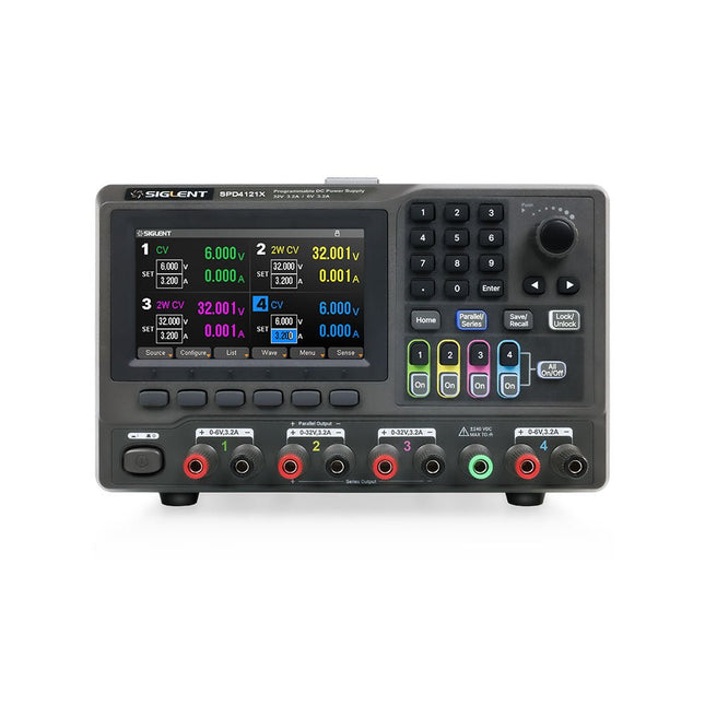
Siglent Siglent SPD4121X 4-ch DC Power Supply (285 W)
The Siglent SPD4121X is a 4-channel DC Linear Programmable Power Supply equipped with a 4.3-inch TFT-LCD display, friendly human-machine interface, and excellent performance indicators. Real-time waveform display provides engineers with an informative user interface. SPD4121X offers a total output power of 285 W with a resolution of 1 mV/1 mA. The maximum voltage and current for each channel are as follows: CH1: 15 V/1.5 A CH2: 12 V/10 A CH3: 12 V/10 A CH4: 15 V/1.5 A Features Rated output power: 285 W Rated voltage: 32 V, 12 V, 30 V Up to four high-precision power supplies with independent controllable outputs, supporting CH2 and CH3 series and parallel connections Clear graphical interface with waveform and timer display modes 5-digit voltage and current display with minimum resolution of 1 mV, 1 mA Fast output response time: <50us The high current channel support remote voltage compensation sense function. The maximum compensation voltage is 0.6 V Overvoltage protection and overcurrent protection or safe and accurate operation Equipped with a 4.3-inch TFT-LCD display (480 x 272 resolution) USB and LAN standard communication USB-GPIB module is optional Excellent channel density with up to 4 channels in a 3U half rack package Internal data storage for setups and parameters Embedded Web Server with instrument communication that doesn’t require software installation Fully SCPI programming command set support as well as a LabView driver for remote control and system automation Specifications SPD4323X SPD4121X SPD4306X Channel Output CH1: Voltage 0 to 6 V Current 0 to 3.2 ACH2: Voltage 0 to 32 V Current 0 to 3.2 ACH3: Voltage 0 to 32 V Current 0 to 3.2 ACH4: Voltage 0 to 6 V Current 0 to 3.2 A CH1: Voltage 0 to 15 V Current 0 to 1.5 ACH2: Voltage 0 to 12 V Current 0 to 10 ACH3: Voltage 0 to 12 V Current 0 to 10 ACH4: Voltage 0 to 15 V Current 0 to 1.5 A CH1: Voltage 0 to 15 V Current 0 to 1.5 ACH2: Voltage 0 to 30 V Current 0 to 6 ACH3: Voltage 0 to 30 V Current 0 to 6 ACH4: Voltage 0 to 15 V Current 0 to 1 A Resolution 1 mV, 1 mA 1 mV, 1 mA 1 mV, 1 mA Setting Accuracy Voltage: ±(0.03% of reading+10) mV, Current: ±(0.3% of reading+10) mA Voltage: ±(0.03% of reading+10) mV, Current: ±(0.3% of reading+10) mA Voltage: ±(0.03% of reading+10) mV, Current: ±(0.3% of reading+10) mA Readback Accuracy Voltage: ±(0.03% of reading+10) mV, Current: ±(0.3% of reading+10) mA Voltage: ±(0.03% of reading+10) mV, Current: ±(0.3% of reading+10) mA Voltage: ±(0.03% of reading+10) mV, Current: ±(0.3% of reading+10) mA Display 4.3" TFT-LCD 5-digit voltage and current display 4.3" TFT-LCD 5-digit voltage and current display 4.3" TFT-LCD 5-digit voltage and current display Output power 240 W 285 W 400 W Included 1x Siglent SPD4121X Power Supply 1x Power cord (EU) 1x Output test cord (3 A) 1x USB cable 1x Quick start guide Downloads Datasheet Manual Quick start
€ 871,20
-

Elektor Classics The Ton Giesberts Collection (USB Stick)
Practical Projects in Analog, Audio and Beyond Discover a remarkable collection of more than 450 electronics projects published in Elektor Magazine and carefully selected by renowned Elektor Lab engineer Ton Giesberts. The USB drive brings together a wide variety of circuits, designs, and practical project ideas created by numerous Elektor authors and engineers over the years. Covering a broad range of electronics topics, this extensive archive is a valuable source of knowledge and inspiration for engineers, makers, students, and electronics enthusiasts. More than 450 selected Elektor projects Carefully compiled by Elektor engineer Ton Giesberts Ideal for building, experimenting, and discovering new ideas Explore decades of Elektor expertise in one comprehensive project collection. Highlights Q-Watt Audio Power Fortissimo-100 High-End Amplifier Buffer Board for the Raspberry Pi 400 USB-to-Multi-Protocol Serial Converter DDS Function Generator AC/DC Power Meter Charge-a-Phone Specifications Storage 8 GB Connectors 1x USB-A1x USB-C System requirements PC with Adobe Reader 7.0 or higher Web browser
€ 49,95€ 39,95Best Price


