Elektor GREEN en GOLD leden kunnen deze uitgave hier downloaden.
Nog geen lid? Klik hier om een lidmaatschap af te sluiten.
MultiRF ontwikkelboardEen platform voor het evalueren van draadloze protocollen op korte en lange afstand
Elektor wordt 65Baanbrekend op het gebied van elektronica sinds 1961
Persoonsdetectie via wifi op een ESP32Wanneer uw router een bewegingssensor wordt
Draadloze weegschalenVier kleine weegschalen maken een grote weegschaal
Walter, de compacte IoT-moduleESP32-S3 SoC, LTE-M/NB-IoT 5G-modem en GNSS-ontvanger
3- en 4-draads RTD-sensorconditioneringMet volledige afstelling en kabelcompensatie
3-in-1 2-kanaals oscilloscoop/generator/multimeterEen review van de Fnirsi 2D15P
electronica Fast Forward 2026 nodigt start-ups en partners uit de industrie uit
EcologgingEen modulair IoT-milieustation voor onderzoek in het veld
Draadloze connectiviteit in medische toepassingenAltijd op de hoogte met Bluetooth LE
AudiotronicaBromonderdrukking
De efficiëntie in de landbouw verhogen met AI-modellen en sensorenDe landbouwproductiviteit verhogen
OPC UA, een overzichtPlatform-onafhankelijke gegevensuitwisseling
Redoxmeter
Instrumentation amplifier voor fysica- en techniekexperimenten
Actieve differentiële audiofiltersVoor professionele cross-overs en meer
Communityperspectieven van Elektor op IoT & sensoren
Telegramgestuurde interface module voor een boilerEen oplossing op basis van een ESP32 en Arduino software
2026: An AI OdysseyWat is er gebeurd met fuzzy logic?
Err-lectronics
Alarmsignaalinjector en bruut geweldHulpmiddelen om kabelbreuken op te sporen
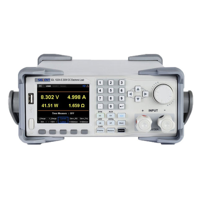
The Siglent SDL1020X-E DC Load leads with measurement resolution of 0.1 mV/0.1 mA and the base SDL1000X-E series resolution is 1 mV/1 mA and adjustable current rise times from 0.001 A/μs~2.5 A/μs. For remote communication and control, the SDL series includes S232/USB/LAN interface types. The SDL1020X-E delivers stability over a wide range of applications and can meet all kinds of testing requirements. including: Power, battery/handheld device design, industry, LED lighting, automotive electronics, and aerospace.
Features
SDL1020X-E (Single channel): DC 150 V/30 A, total power 200 W
4 static modes / Dynamic mode: CC/CV/CR/CP
CC Dynamic mode: Continuous, pulsed, toggled
CC Dynamic mode: 25 kHz, CP Dynamic mode: 12.5 kHz, CV Dynamic mode: 0.5 Hz
Measuring speed of voltage and current: up to 500 kHz
Adjustable current rise time range: 0.001 A/us~2.5 A/us
Min. readback resolution: 0.1 mV, 0.1 mA
Short-circuit, Battery test, CR-LED mode, and factory test functions
4-wire SENSE compensation mode function
List function supports editing as many as 100 steps
Program function supports 50 groups of steps
OCP, OVP, OPP, OTP and LRV protection
External analog control
Voltage, Current monitoring via 0-10 V
3.5 inch TFT-LCD display, capable of displaying multiple parameters and states simultaneously
Built-in RS232/USB/LAN communication interface, USB-GPIB module (optional)
Waveform trend chart and easy-to-use file storage and call functions
Includes PC software: Supports SCPI, LabView driver
Included
1x Siglent SDL1020X-E DC Programmable Load
1x Quick start guide
1x Guarantee Card
1x Power Cord
1x USB Cable
Downloads
Datasheet
Manual
Programming Guide
PC Software
STmicroelectronics’ wireless IoT & wearable sensor development kit
‘SensorTile.box’ is a portable multi-sensor circuit board housed in a plastic box and developed by STMicroelectronics. It is equipped with a high-performance 32-bit ARM Cortex-M4 processor with DSP and FPU, and various sensor modules, such as accelerometer, gyroscope, temperature sensor, humidity sensor, atmospheric pressure sensor, microphone, and so on. SensorTile.box is ready to use with wireless IoT and Bluetooth connectivity that can easily be used with an iOS or Android compatible smartphone, regardless of the level of expertise of the users. SensorTile.box is shipped with a long-life battery and all the user has to do is connect the battery to the circuit to start using the box.
The SensorTile.box can be operated in three modes: Basic mode, Expert mode, and Pro mode. Basic mode is the easiest way of using the box since it is pre-loaded with demo apps and all the user has to do is choose the required apps and display or plot the measured data on a smartphone using an app called STE BLE Sensor. In Expert mode users can develop simple apps using a graphical wizard provided with the STE BLE Sensor. Pro mode is the most complex mode allowing users to develop programs and upload them to the SensorTile.box.
This book is an introduction to the SensorTile.box and includes the following:
Brief specifications of the SensorTile.box; description of how to install the STE BLE Sensor app on an iOS or Android compatible smartphone required to communicate with the box.
Operation of the SensorTile.box in Basic mode is described in detail by going through all of the pre-loaded demo apps, explaining how to run these apps through a smartphone.
An introduction to the Expert mode with many example apps developed and explained in detail enabling users to develop their own apps in this mode. Again, the STE BLE Sensor app is used on the smartphone to communicate with the SensorTile.box and to run the developed apps.
The book then describes in detail how to upload the sensor data to the cloud. This is an important topic since it allows the sensor measurements to be accessed from anywhere with an Internet connection, at any time.
Finally, Pro mode is described in detail where more experienced people can use the SensorTile.box to develop, debug, and test their own apps using the STM32 open development environment (STM32 ODE). The Chapter explains how to upload the developed firmware to the SensorTile.box using several methods. Additionally, the installation and use of the Unicleo-GUI package is described with reference to the SensorTile.box. This PC software package enables all of the SensorTile.box sensor measurements to be displayed or plotted in real time on the PC.
Theory, LTspice Simulation, and Hands-On Projects
MOSFETs are essential components in modern electronics, used in switching, amplification, motor control, power conversion, digital logic, and audio circuits. This book offers a practical introduction to MOSFET technology, combining clear explanations with LTspice simulations and hands-on projects.
Starting with semiconductor fundamentals, you will learn how MOSFETs operate, how they compare with BJTs, and how to apply them in real circuits. The book then progresses from basic switching applications to more advanced designs.
You will learn how to:
Understand N-channel and P-channel MOSFET operation
Work with cutoff, triode, and saturation regions
Simulate and analyze circuits using LTspice
Build switching circuits for LEDs, relays, buzzers, sensors, and motors
Create sensor circuits for light, temperature, touch, tilt, reed switches, and PIR motion detection
Control motors and fans using PWM and H-bridge circuits
Design MOSFET small-signal amplifiers
Build astable, Colpitts, Hartley, phase-shift, and Pierce oscillators
Experiment with MOSFET digital logic
Explore buck and boost DC-DC converters
Understand the basics of MOSFET audio power amplifiers
Written for engineers, students, and experienced makers, this book connects theory with simulation and practical construction, giving you the knowledge and experience to design and experiment with MOSFET circuits with confidence.
The OWON SDS1104 oscilloscope is a practical choice for engineers, technicians, students, and hobbyists who need accurate signal analysis without the cost of high-end instruments. With its 100 MHz bandwidth and 1 GSa/s sampling rate, it reliably captures low- to mid-frequency signals, making it well suited for electronics development, troubleshooting, and educational use.
Equipped with a 7-inch color TFT display, the SDS1104 provides clear waveform visualization, while automatic measurement functions and FFT analysis help users quickly evaluate frequency, voltage, and timing parameters. Advanced math operations, cursor measurements, and multiple trigger modes add further flexibility, making the oscilloscope a versatile tool for a wide range of testing scenarios.
Specifications
Bandwidth
100 MHz
Sample Rate
1 GS/s
Horizontal Scale (s/div)
5ns/div - 1000s/div, step by 1 - 2 - 5
Channel
4
Display
7" color LCD, 800 x 480 pixels
Input Coupling
DC, AC and GND
Vertical Resolution (A/D)
Vertical Resolution (A/D)
Vertical Sensitivity
5mV/div - 5V/div (at input)
Trigger Type
Edge, Video
Trigger Mode
Auto, Normal and Single
Waveform Math
+, -, x, ÷, invert, FFT
Fuse
2A, T class, 250 V
Dimension (W x H x D)
301 x 152 x 70 mm
Weight
1.1 kg
Included
1x OWON SDS1104 Oscilloscope
1x Mains power cord
1x CD Rom
1x Quickstart Guide
1x USB Cable
4x Oscilloscope probe
1x Probe Adjust
Downloads
Datasheet
Manual
ZELFBOUW LIPO-SUPERCHARGER KITvan prototype tot productie
ELEKTOR @ 60gedachten bij zestig jaar elektronica
SIGLENT SDM3045X TAFELMULTIMETER
DC-STROOMKLEMHall-sensor + ferrietkern + Arduino
SOLDEERSTATION 2021makkelijk om te bouwen!
KENNISMAKING MET DE PARALLAX PROPELLER 2 (DEEL 2)de ontwikkelomgeving en de code
WIFI VOOR DE LORA SWITCHgeïntegreerd in Home Assistant met ESPHome
GEEN ANGST VOOR DE CELLULAIRE MODULE!
HOUD DE TIJD BIJ MET ESP32 EN TOGGLwerken met de M5Stack
KENNISMAKING MET HET RASPBERRY PI PICO-BOARD EN DE RP2040
MICROPYTHON VOOR MICROCONTROLLERStechnieken voor kleine displays
12–200 V DC/DC-CONVERTERvoor buizenversterkers
WARMTEZOEKERde Seek Shot Pro warmtebeeldcamera
OBJECTGEORIËNTEERD PROGRAMMERENeen korte inleiding met C++
OOST WEST LAB BEST...waar Kurt Diedrich synthesizers bouwt
JAVA OP DE RASPBERRY PIdeel 1: GPIO’s
DIP-SCHAKELAARSvreemde onderdelen
INTERACTIEFcorrecties & updates || brieven van lezers
WIENS PRODUCT IS HET EIGENLIJK?recht-op-reparatie beweging laat van zich horen
UIT HET LEVEN GEGREPENhet grote blunderboek
MICRO-PROFESSORassembleertaal leren op een Z80
ALLE BEGIN......hoeft niet zo moeilijk te zijn – zelfs als het om condensatoren gaat
HEXADOKUThe Original Elektorized Sudoku
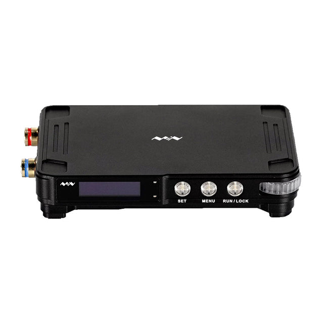
MDP-P906 has a built-in cooling fan, and maximum output power of up to 300 W, which meets a wider range of testing needs and application scenarios. Through 2.4 GHz wireless communication, it can be connected to MDP-M01 Smart Digital Monitor module to realize the free combination of multiple channels of 300 W per channel.
MDP-P906 has the index, stability and reliability comparable to a professional power supply. It can output pure current, and provide powerful functions such as programmable output, timing output, timing control, automatic compensation, boost mode, etc., making itself a real cost-effective, smart and customized programmable linear DC power supply.
MDP-P906 adopts a precision CNC machined aluminum alloy shell, with fine workmanship, novel, mini and beautiful appearance, it completely subverts the rigid image of traditional desktop power supply. With stackable modular design and wireless communication function, MDP-P906 can work independently or paired, both on the workbench, and be carried out for on-site maintenance. MDP-P906 is a perfect solution for electronic engineer, especially field application engineers to meet different needs of power sources.
Built-in silent cooling fan, instant cooling, ensure a stable and efficient output!
Smart linear compensation, constant voltage & constant current
Positive & negative output, series boost, parallel current sharing
Applications
Universal tests and teaching experiments in R&D laboratory
Maintenance of digital products
Property verification and fault diagnosis of devices and circuits
Emergency power supply for model airplanes and vehicles
Power supply testing of RF and microwave circuits or modules
Quality control and quality inspection
Supply purified power for high-accuracy digital-analog hybrid circuits and Hi-Fi audio devices
Specifications
Input
DC 4.2-30 V/14 A (Max)QC 3.0/PD2.0, 20 V/5 A (Max)
Output
0-30 V/0-10 A, 300 W (Max)
Conversion efficiency
95%
Output resolution
10 mV/2 mA, up to 1 mV/1 mA via Display Control module
Output accuracy
0.03%+5 mV0.05%+2 mV
Adjustment rate
Load adjustment rate <±0.01%Power adjustment rate <±0.01%
Ripple and noise
<250 uVrms, 3 mVpp; 2 mArms
Transient response
<4 uS
Safety protections
Input over-voltage, under-voltage, reverse connection protection, output over-current, back-flow protection and over-temperature protection
Others
Automatically shut-down and enter micro-power modeSupport USB firmware upgrade
Dimensions
112 x 66 x 20 mm
Weight
181 g
Included
1x MDP-P906 Digital Power Supply
2x Output Cable
1x User Manual
Downloads
User Manual v1.1
Firmware v1.32
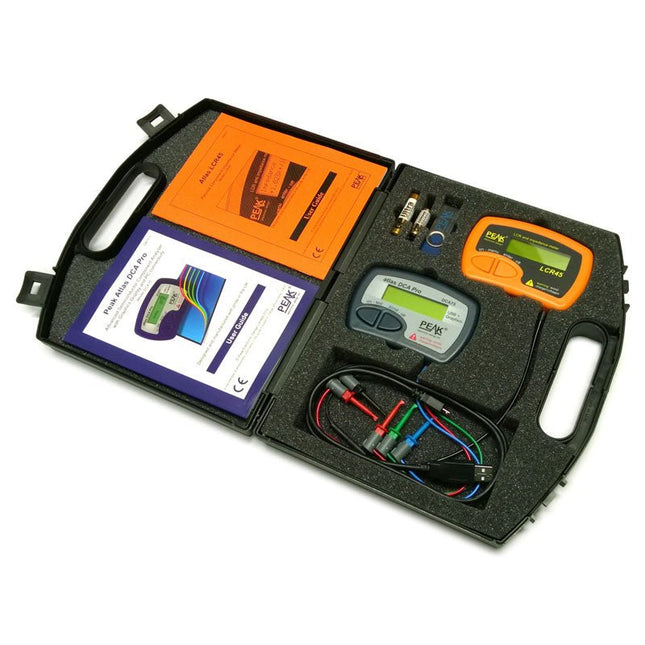
This pack contains the LCR45 Passive Component Impedance Meter, great for advanced hobbyists and professionals. It also contains the very popular DCA Pro (model DCA75), fantastic for component identification, pinout identification, detailed characteristic measurement and curve tracing on a PC. Complete with USB cable and software on a USB flash drive.
DCA75
Building on the continued success of Peak's existing component identification and analysis instruments, the DCA Pro brings an array of exciting new features for the hobbyist and professional alike.
The DCA Pro is an advanced new design that features a graphics display, USB communications, PC Software and an enhanced component identification library.
Automatic component type identification
Automatic pinout identification (connect any way round)
The DCA Pro supports all the components that the popular Peak Atlas DCA55 supports, but adds plenty more. Components supported include:
Transistors (including Darlingtons), Silicon and Germanium types. Measures gain, Vbe and leakage
MOSFETs, enhancement mode and depletion mode types. Measure on-threshold (at 5 mA) and approx transconductance (for span of 3-5 mA)
JFETs, including normally off SiC types. Measures pinch-off voltage (at 1 uA) and approx transconductance (for span of 3-5 mA)
IGBTs (insulated gate bipolar transistors). Measures on-threshold (at 5 mA)
Diodes and Diode networks
LEDs and bicolour LEDs (2 lead and 3 lead types)
Zener Diodes with measurement of zener voltage up to 9 V at 5 mA
Voltage regulators (measures regulation voltage, drop-out voltage, quiescent current)
Triacs and Thyristors that require less than 10 mA of gate current and holding current
Stand-alone or with a PC
The instrument can be used stand-alone or connected to a PC. Either way, the DCA Pro will automatically identify the component type, identify the pinout and also measure a range of component parameters such as transistor gain, leakage, MOSFET and IGBT threshold voltages, pn characteristics and much more.
Curve Tracing
When connected to a PC using the supplied USB cable, a range of low current curve-tracing functions can be performed. Various graph types are available, with more to follow:
Bipolar transistor output characteristics, IC vs VCE
Bipolar transistor gain characteristics, HFE vs VCE
Bipolar transistor gain characteristics, HFE vs IC
MOSFET and IGBT output function, ID vs VDS
MOSFET and IGBT transfer function, ID vs VGS
JFET output function, ID vs VDS
JFET transfer function, ID vs VGS
Voltage regulator, VOUT vs VIN
Voltage regulator, IQ vs VIN.
PN junction I/V curves, forward and reverse options (for Zener diodes)
Curve tracing is performed using test parameters in the range of +/-12 V or +/-12 mA. All curve-tracing data can be instantly pasted into Excel for further graphing and analysis. PC Software is included with the DCA Pro on a Peak USB memory stick. Software designed for Windows 7 and higher (all 32 or 64 bit).
LCR45
A great handheld LCR analyzer that can measure the value of your passive component (inductor, capacitor or resistor) and also measure the detailed impedance in a number of modes. The LCR45 offers enhanced measurement resolution (better than 0.1 uH!) whilst also giving you continuous fluid measurements. Additionally, the test frequencies of DC, 1 kHz, 15 kHz and 200 kHz can be set to automatic or manual modes. Supplied with removable gold plated hook probes, battery and user guide. Compatible with standard 2 mm test connectors. Not designed for in-circuit use.
Automatic or manual component type selection: Inductor, Capacitor or Resistor
Automatic or manual test frequency selection: DC, 1 kHz, 15 kHz and 200 kHz
Inductance from 0.1 uH to 10 H
Capacitance from 0.1 pF to 10,000 uF
Resistance from 0.1 Ohm to 2 MOhm
Inductance measurement also shows DC winding resistance
Display of "Component type and values", "Complex Impedance", "Magnitude/Phase" and "Admittance"
Test frequency displayed for all measurements
Typical accuracy of 1.5% for inductors and capacitors (see spec table for details)
Typical accuracy of 1% for resistors
Test lead complete with gold plated 2 mm plugs and sockets
Supplied with removable gold plated hook probes
Included
LCR45
DCA75
Extra GP23 Battery
Extra AAA cell
Dual Carry Case
Diese Ausgabe steht allen GOLD- und GREEN-Mitgliedern auf der ElektorMagazine-Website zum Download bereit!
Sie sind noch kein Mitglied? Hier klicken!
PbMonitor v1.0Ein Batterieüberwachungssystem für USV und Energiespeicher
Solarladeregler mit MPP-TrackingTeil 1: Grundlagen eines Solarreglers für Insel-Anlagen
B-Feld-Integrationsmagnetometer mit selbstgebauten Sensoren
Präzise, richtig oder genau?Ihre Messgeräte müssen alles sein!
AD7124 – Ein Präzisions-ADC in der PraxisHinweise für die Sensor-Signalaufbereitung
PID-RegelungswerkzeugOptimieren Sie ganz einfach Ihre Parameter
embedded world 2025
Aller Anfang ......muss nicht schwer sein: Klangeinstellung!
Academy Pro BoxBook + Online Course + Hardware
Milliohmmeter-AdapterNutzen Sie die Präzision Ihres Multimeters!
Der nächste Meilenstein bei HalbleiternWeiter in Richtung 1,4 nm
Steckverbinder in DurchstecktechnikDas Beste aus zwei Welten: THR
FrequenzzählerPortabel und mit automatischer GPS-Kalibrierung
Analoge MessgeräteBemerkenswerte Bauteile
Stand-alone-QuarztesterWie genau ist Ihre Taktquelle?
Preiswerter I²C-TesterSchließen Sie I²C-Chips direkt an Ihren PC an
Aus dem Leben gegriffenWer das Kleine nicht ehrt...
2025: Eine Odyssee in die KIDie transformativen Auswirkungen auf die Softwareentwicklung
Projekt 2.0Korrekturen, Updates und Leserbriefe
Standalone-MIDI-Synthesizer mit Raspberry PiTeil 2: Setup mit Intelligenz aufwerten
Nortonisierter Wien-Brücken-OszillatorKleine Änderungen führen zu bedeutenden Verbesserungen
10-Cent-Controller in der PraxisRISC-V-Mikrocontroller CH32V003 und MounRiver Studio ausprobiert
Audio-Player mit FPGA und EqualizerTeil 2: Lautstärkeregelung, erweitertes Mischen und ein Web-Interface
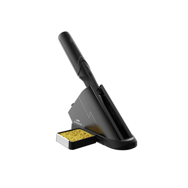
The Miniware Cordless Soldering Station TS1C (with integrated OLED screen and Bluetooth) is an intelligent soldering tool that heats up to 400°C in less than 20 seconds. Thanks to the built-in battery, the wireless soldering pen sits comfortably in the hand and is easy to use.
Features
New high-efficiency supercapacitor energy storage technology, 10,000-level charge and discharge times
Seperate design + true wireless, enjoy wireless soldering experience
BLE4.2 Bluetooth communication technology to realize remote control and setting
Standard PD2 20 V 45 W max power input, up to 36 W soldering power, can continuously solder more than 180 solder joints (0805) with a single full charge
Control station preheating to improve heating efficiency
3 expansion slots for accessories
Control Station
Standard PD2 20 V 45 W max power input, over current safety protection
128x64 pixel OLED screen, display soldering pen status in real time
Control station preheating, improve heating efficiency
Remote control and setting: temperature regulating, menu setting, viewing device info and status, etc.
Work as soldering stand and charging station
3 expansion slots for multiple expandable accessories like sponge slot
Soldering Pen
Built-in 750F high-efficiency energy storage supercapacitor, can be charged via control station (or via its USB Type-C interface in emergency cases)
36 W maximum heating power, can solder more than 180 solder joints (0805) continuously under a single full charge
Compatible with Miniware 3.5 mm audio interface soldering tips (TS80/80P soldering tip series)
Boost mode (holding the button on the pen)
Included
TS1C Soldering pen
TS1C Control station
Soldering tip (TS-B02)
Silicone cable
Sponge slot incl. sponge
Manual