
Search results for "miniware OR dt71 OR mini OR digital OR tweezers"
-
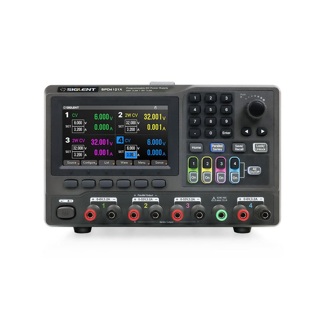
Siglent Siglent SPD4121X 4-ch DC Power Supply (285 W)
The Siglent SPD4121X is a 4-channel DC Linear Programmable Power Supply equipped with a 4.3-inch TFT-LCD display, friendly human-machine interface, and excellent performance indicators. Real-time waveform display provides engineers with an informative user interface. SPD4121X offers a total output power of 285 W with a resolution of 1 mV/1 mA. The maximum voltage and current for each channel are as follows: CH1: 15 V/1.5 A CH2: 12 V/10 A CH3: 12 V/10 A CH4: 15 V/1.5 A Features Rated output power: 285 W Rated voltage: 32 V, 12 V, 30 V Up to four high-precision power supplies with independent controllable outputs, supporting CH2 and CH3 series and parallel connections Clear graphical interface with waveform and timer display modes 5-digit voltage and current display with minimum resolution of 1 mV, 1 mA Fast output response time: <50us The high current channel support remote voltage compensation sense function. The maximum compensation voltage is 0.6 V Overvoltage protection and overcurrent protection or safe and accurate operation Equipped with a 4.3-inch TFT-LCD display (480 x 272 resolution) USB and LAN standard communication USB-GPIB module is optional Excellent channel density with up to 4 channels in a 3U half rack package Internal data storage for setups and parameters Embedded Web Server with instrument communication that doesn’t require software installation Fully SCPI programming command set support as well as a LabView driver for remote control and system automation Specifications SPD4323X SPD4121X SPD4306X Channel Output CH1: Voltage 0 to 6 V Current 0 to 3.2 ACH2: Voltage 0 to 32 V Current 0 to 3.2 ACH3: Voltage 0 to 32 V Current 0 to 3.2 ACH4: Voltage 0 to 6 V Current 0 to 3.2 A CH1: Voltage 0 to 15 V Current 0 to 1.5 ACH2: Voltage 0 to 12 V Current 0 to 10 ACH3: Voltage 0 to 12 V Current 0 to 10 ACH4: Voltage 0 to 15 V Current 0 to 1.5 A CH1: Voltage 0 to 15 V Current 0 to 1.5 ACH2: Voltage 0 to 30 V Current 0 to 6 ACH3: Voltage 0 to 30 V Current 0 to 6 ACH4: Voltage 0 to 15 V Current 0 to 1 A Resolution 1 mV, 1 mA 1 mV, 1 mA 1 mV, 1 mA Setting Accuracy Voltage: ±(0.03% of reading+10) mV, Current: ±(0.3% of reading+10) mA Voltage: ±(0.03% of reading+10) mV, Current: ±(0.3% of reading+10) mA Voltage: ±(0.03% of reading+10) mV, Current: ±(0.3% of reading+10) mA Readback Accuracy Voltage: ±(0.03% of reading+10) mV, Current: ±(0.3% of reading+10) mA Voltage: ±(0.03% of reading+10) mV, Current: ±(0.3% of reading+10) mA Voltage: ±(0.03% of reading+10) mV, Current: ±(0.3% of reading+10) mA Display 4.3" TFT-LCD 5-digit voltage and current display 4.3" TFT-LCD 5-digit voltage and current display 4.3" TFT-LCD 5-digit voltage and current display Output power 240 W 285 W 400 W Included 1x Siglent SPD4121X Power Supply 1x Power cord (EU) 1x Output test cord (3 A) 1x USB cable 1x Quick start guide Downloads Datasheet Manual Quick start
€ 871,20
-

OWON OWON OW18B True RMS Multimeter
Features Data-logger & Multimeter & Thermometer 3 (5/6) digits True RMS test supported BLE 4.0 wireless transmission, more stable, less power consumption Chart and Diagram mode, to analyze your data Supports NCV Voice Broadcast simplifies testing Flashlight function Built-in offline recording function Supports Android, iOS Included Test leads K-type thermocouple 9 V Battery Bolt driver Crocodile clip Quick guide
€ 39,63
-

Elektor Digital Elektor Januari/Februari 2021 (PDF)
ZELFBOUW LIPO- SUPERCHARGER-BUNDELLiPo-lader, -booster en -beveiliging van GreatScott en Elektor MTHECAM – DE MINI-THERMOCAMERAeenvoudige warmtebeeldcamera voor het lokaliseren van hot- en coldspots REVIEW: WELLER-SOLDEERSTATION WE 1010 ELECTRONICA FAST FORWARD 2020 – DE WINNAARS I2S TESTSIGNAALGENERATOR MET AVR-MICROCONTROLLER32-bit 1-kHz digitale sinus, fs 192 kHz, niveau instelbaar van 0 tot –110 dB DOMOTICA MET DE RASPBERRY PIRPi luistert op 433,92 MHz SCHAKELINGEN ONLINE SIMULEREN UIT HET LEVEN GEGREPENde dunne grens tussen orde en chaos ALLE BEGIN......hoeft niet zo moeilijk te zijn OOST WEST LAB BESTeen blik in het allerheiligste, waar interessante projecten worden geboren VERBIND UW THERMOSTAAT MET ESPHOMEeen poging om domotica op de juiste manier te doen DEVELOPER’S ZONEtips & trucs, vakkunstigheden en andere nuttige informatie WIE HET KLEINE NIET EERTuit de ideeënbus van Elektor RASPBERRY PI FULL STACKRPi en RF24 als hart van een sensornetwerk MULTITASKING MET DE ESP32 (6)event groups MEERKANAALS POWER ANALYZERtot 3 kanalen, met grafisch en alfanumeriek display ANALOGE ELEKTRONICA ONTWERPENcase-study #2 – deel 3: passieve filters REVIEW: DRAADLOZE MEETMODULE JOY-IT VAX-1030 NIEUWE LCR-METER 50 HZ – 2 MHZ (DEEL 2)bediening, kalibratie en programmeren van de firmware ERROR ANALYSIStips en trucs: spanningsregelaars, PCB-ontwerp en meer HET OPEN HARDWARE OBSERVATORYcommunitygebaseerde beoordeling van open source-hardware JAVA OP DE RASPBERRY PIeen vraaggesprek met Frank Delporte DATA-ANALYSE EN KUNSTMATIGE INTELLIGENTIE IN PYTHONechte gegevens interpreteren met NumPy, pandas en scikit-learn INTERACTIEFcorrecties & updates || brieven van lezers ONZE COMMUNITY IN CIJFERS KENNISMAKING MET DE PARALLAX PROPELLER 2 (DEEL 1)inleiding HEXADOKU
€ 9,95
-
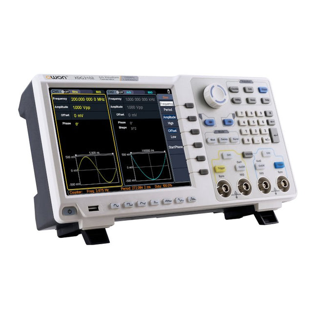
OWON OWON XDG3102 2-ch Arbitrary Waveform Generator (100 MHz)
Features Advanced DDS technology, up to 250 MHz frequency output 1.25 GS/s sampling rate, and 1 μHz frequency resolution Up to 1M arbitrary waveform length Vertical resolution: 14 bits Comprehensive waveform output: 6 groups waveforms, and 152 group built-in arbitrary waveforms Comprehensive modulation options: AM, FM, PM, FSK, 3FSK, 4FSK, PSK, OSK, ASK, BPSK, PWM, sweep, and burst High-accuracy frequency counter integrated, ranging from 100MHz till 200MHz SCPI and LabVIEW supported 8-inch 800 x 600 pixels touch screen LCD Specifications XDG3102 Channel 2 Frequency Output 100MHz Sample Rate 1.25GSa/s Vertical Resolution 14 bits Waveform Standard Waveform sine, square, pulse, ramp, noise, and harmonic Arbitrary Waveform exponential rise, exponential fall, sin(x)/x, step wave, and others, total of 150 built-in waveforms, and user-defined arbitrary waveform Frequency (resolution 1μHz) Sine 1μHz - 100MHz Square 1μHz - 40MHz Pulse 1μHz - 25MHz Ramp 1μHz - 5MHz Harmonic 1μHz - 50MHz Noise 120MHz (-3dB, typical) Arbitrary Waveform built-in waveform: 1uHz - 15MHzuser-defined waveform: 1uHz - 50MHz Accuracy ±1ppm, 0°C - 40°C Amplitude Amplitude (50Ω) 1mVpp - 10Vpp (≤40MHz); 1mVpp - 5Vpp (≤80MHz) 1mVpp - 2.5Vpp (≤120MHz); 1mVpp - 1Vpp (≤250MHz) Amplitude(high impedance) 2mVpp - 20Vpp (≤40MHz); 2mVpp - 10Vpp (≤80MHz); 2mVpp - 5Vpp (≤120MHz); 2mVpp - 2Vpp (≤250MHz) Resolution 1mV or 4 digits DC Offset Range (50Ω) ±(5 Vpk - Amplitude Vpp/2) Range (high-Z, open circuit) ±(10 Vpk - Amplitude Vpp/2) Accuracy ±(1% of |setting| + 1mV + Amplitude Vpp x 0.5%) Resolution 1mV or 4 digits Load Impedance 50Ω (typical) Accuracy ±(1% of setting + 1 mVpp) (typical, 1kHz sine, 0V offset) Sine Wave Spectrum Purity Harmonic Distortion Typical (0dB) DC - 1MHz: <-65dBc 1MHz - 10MHz: <-60dBc 10MHz - 120MHz: <-50dBc 120MHz - 200MHz: <-45dBc Total Harmonic Distortion <0.05 %, 10 Hz to 20 kHz, 1 Vpp Spurious (non-harmonic), Typical (0dB) ≤10MHz: <-70dBc >10MHz: <-70dBc + 6dB/ octave Phase Noise Typical (0 dBm, 10 kHz deviation) 10MHz: ≤-110dBc/Hz Square Rise/Fall Time <5ns Overshoot <3% Duty Cycle 50.0% (fixed) Jitter (rms) 300ps + 100ppm Pulse Pulse Width 12ns - 996875s Leading/Trailing Edge Time ≧7ns Overshoot <3% Jitter (rms) 300ps + 100ppm Ramp Linearity ≤1% of peak output (typical, 1kHz, 1 Vpp, 50% symmetry) Symmetry 0% to 100% Harmonic Harmonic Order ≤16 Harmonic Type even, odd, all, user Harmonic Amplitude could be set for all the harmonics Harmonic Phase Arbitrary Waveform Length 2 points - 1M points Vertical Resolution 14 bits Minimum Rise/Fall Time <7ns Jitter (rms) 3ns Modulation Type AM, FM, PM, PWM, FSK, 3FSK, 4FSK, PSK, OSK, ASK, BPSK, sweep, and burst AM Carrier Waveform sine, square, ramp, and arbitrary (except DC) Source internal / external Modulating Waveform sine, square, ramp, noise, and arbitrary Depth 0.0% - 100.0% Modulating Frequency 2 mHz - 100 kHz FM Carrier Waveform sine, square, ramp, and arbitrary (except DC) Source internal / external Modulating Waveform sine, square, ramp, noise, and arbitrary Modulating Frequency 2 mHz - 100 kHz PM Carrier Waveform sine, square, ramp, and arbitrary (except DC) Source internal / external Modulating Waveform sine, square, ramp, noise, and arbitrary Phase Deviation 0° - 180° Modulating Frequency 2 mHz - 100 kHz PWM Carrier Waveform pulse Source internal / external Modulating Waveform sine, square, ramp, noise, and arbitrary Width Deviation 0 ~ minimum (pulse duty ratio, 100% - pulse duty ratio) Modulating Frequency 2 mHz - 100 kHz FSK / 3FSK / 4FSK Carrier Waveform sine, square, ramp, and arbitrary (except DC) Source internal / external Modulating Waveform square with 50% duty cycle Key Frequency 2 mHz - 1MHz PSK Carrier Waveform sine, square, ramp, and arbitrary (except DC) Source internal / external Modulating Waveform square with 50% duty cycle Key Frequency 2 mHz - 1MHz OSK Carrier Waveform sine, square, ramp, and arbitrary (except DC) Source internal Oscillation Time square with 50% duty cycle Key Frequency 2 mHz - 1MHz ASK Carrier Waveform sine, square, ramp, and arbitrary (except DC) Source internal / external Modulating Waveform square with 50% duty cycle Key Frequency 2 mHz - 1MHz BPSK Carrier Waveform sine, square, ramp, and arbitrary (except DC) Source internal Modulating Waveform square with 50% duty cycle Key Frequency 2 mHz - 1MHz Sweep Carrier Waveform sine, square, ramp, and arbitrary (except DC) Type linear, and log Direction up, and down Sweep Time 1 ms to 500s, ± 0.1% Trigger Source internal, external, and manual Burst Carrier Waveform sine, square, ramp, pulse, and arbitrary (except DC) Burst Count 1 to 50,000 period, infinite, gating Internal Period 10 ns - 500 s Gated Source external trigger Frequency Counter Function frequency period, +width, -width, +duty, and -duty Frequency Range 100 MHz - 200 MHz Frequency Resolution 7 digits Input / Output Display 8”800 x 600 pixels touch screen LCD Type frequency counter, external modulation input,external trigger input,external reference clock input / output Communication Interface USB Host, USB Device, and LAN Dimension 340 x 177 x 90 mm Weight 2.50 kg
€ 650,00
-

Elektor Digital Supersnel PC Interfacen (E-book)
Wilt u in enkele minuten een programma maken op uw PC, dat communiceert met een microcontroller? Dit boek, samen met de Piccolino en gratis software, maakt dat mogelijk! Als hardware wordt gebruik gemaakt van de Piccolino. Dit is een prototype platform met een moderne PIC16F887 microcontroller, dat gebruikt kan worden om razendsnel microcontroller opstellingen te maken. Alle basisvoorzieningen zijn aanwezig op de Piccolino, en door middel van de headers kunnen extra onderdelen eenvoudig aangesloten worden. De Piccolino wordt geprogrammeerd met de krachtige maar eenvoudig te leren gratis programmeertaal JAL. Deze taal wordt zowel door hobbyisten als professionals gebruikt. Bovendien is een serie projectboeken in deze taal verkrijgbaar, en een lesboek waarmee u JAL kunt leren. Aan de PC kant wordt gebruik gemaakt van de eveneens eenvoudig te leren gratis programmeertaal Small Basic van Microsoft. Deze taal is speciaal ontwikkeld om snel Windows programma's te kunnen ontwikkelen, ook voor mensen die weinig of geen PC programmeer ervaring hebben. U leert verschillende technieken om een PC met een microcontroller te laten communiceren zoals losse communicatie, het versterken en verzwakken van signalen, verwerken van valse metingen, master-slave communicatie en synchronisatie met geforceerde reset. Behalve theorie staan in het boek ook 15 leuke en praktische projecten. Door de duidelijke uitleg en instructies kunt u deze projecten zelf uitbreiden en helemaal aan uw eigen wensen aanpassen. Een paar voorbeelden uit het boek: Meet signalen en toon ze op de PC Maak een eigen muis of keyboard besturing. Meet en analyseer componenten (Spoel / Condensator / Transistor / OPAMP) met automatische grafieken op uw PC. Bestuur een servomotor vanaf de PC. Verzamel metingen in de Piccolino en zet ze later over naar uw PC. De combinatie van theorie en praktijkvoorbeelden in dit boek zorgt er voor dat u voor elk interface-probleem een oplossing bij de hand hebt, of weet hoe u er een moet maken.
€ 29,95
Members: € 26,96
-

Elektor Digital PIC Cookbook for Virtual Instrumentation (E-book)
The software simulation of gauges, control-knobs, meters and indicators which behave just like real hardware components on a PC’s screen is known as virtual instrumentation. In this book, the Delphi program is used to create these mimics and PIC based external sensors are connected via a USB/RS232 converter communication link to a PC. Detailed case studies in this Book include a virtual compass displayed on the PC’s screen, a virtual digital storage oscilloscope, virtual -50 to +125 degree C thermometer, and FFT sound analyser, a joystick mouse and many examples detailing virtual instrumentation Delphi components. Arizona’s embedded microcontrollers – the PIC's are used in the projects and include PIC16F84A, PIC16C71, DSPIC30F6012A, PIC16F877, PIC12F629 and the PIC16F887. Much use is made of Microchip’s 44 pin development board (a virtual instrument ‘engine)’, equipped with a PIC16F887 with an onboard potentiometer in conjunction with the PIC’s ADC to simulate the generation of a variable voltage from a sensor/transducer, a UART to enable PC RS232 communications and a bank of 8 LED's to monitor received data is also equipped with an ISP connector to which the ‘PICKIT 2’ programmer may easily be connected. Full source code examples are provided both for several different PIC’s, both in assembler and C, together with the Pascal code for the Delphi programs which use different 3rd party Delphi virtual components.
€ 19,95
Members: € 17,96
-

Elektor Digital Digital Electronics (E-book)
The Basics, New Ideas & Applications Build digital electronics from the ground up—and take it all the way to practical circuits you can use. This book guides you through the core principles of digital technology with a strongly hands-on approach. You’ll begin with the essentials: signals, devices for working with them, and what "logic 0" and "logic 1" mean in real hardware. Simple demonstration setups made from easy-to-find parts (LEDs, diodes, resistors, switches) help you see how logic behaves, making the theory click before you move on. From there, you’ll explore a wide range of logic elements and how they’re implemented, including classic logic families such as TTL and CMOS. The fundamentals section covers the building blocks of digital systems: flip-flops, Schmitt triggers, registers, counters and dividers, encoders/ decoders, multiplexers/demultiplexers, plus A/D and D/A conversion and timing circuits. Next, the book invites you into "new ideas" in digital electronics—universal logic elements, unconventional approaches (including thyristor-based and fractional logic), and creative logic functions that can inspire original designs. Finally, a large, well-organized collection of application circuits turns knowledge into projects: electronic switches and selectors, pulse generators, PWM regulators, frequency multipliers/dividers, phase shifters, and digital filters. Study it deeply, and you’ll gain not only understanding—but the ability to design and debug digital circuits independently.
€ 32,95
Members: € 29,66
-

Elektor Digital Das 1-Wire-Praxisbuch (PDF)
1-Wire ist die Bezeichnung für eine serielle Schnittstelle, die mit nur einer Datenader auskommt. Es ist ein Master-Multi-Slave-Kommunikationsprotokoll. Verfügbar sind integrierte Bausteine zur Temperaturmessung, Akkuüberwachung, Echtzeituhr und beispielsweise Hotelschließanlagen. Eine Besonderheit von 1-Wire-Geräten ist die Spannungsversorgung aus der Gegenstation, hierbei erfolgt die Versorgung der Slaves über die Datenleitung. Der Leser erhält mit „Das 1-Wire-Praxisbuch“ eine umfassende Einführung in die 1-Wire-Technologie. Das Buch zeigt anhand praktischer Projekte zum Nachbauen, wie man verschiedene verfügbare 1-Wire-Chips in eigene Mikrocontroller-gesteuerte Anwendungen integrieren kann, und zwar mit Assembler-Software-Implementierungen für PIC-Mikrocontroller und mit Sketches für den Arduino. Die 1-Wire-Technik kommt in dem Buch praxisnah bei einem elektronischen Schloss zum Einsatz, das von einem PIC-Mikrocontroller gesteuert wird. Ein weiteres Praxisprojekt erläutert Schritt für Schritt, wie beispielsweise eine ständige Temperaturmessung mit 1-Wire-Bausteinen möglich ist.
€ 32,80
Members: € 29,52
-
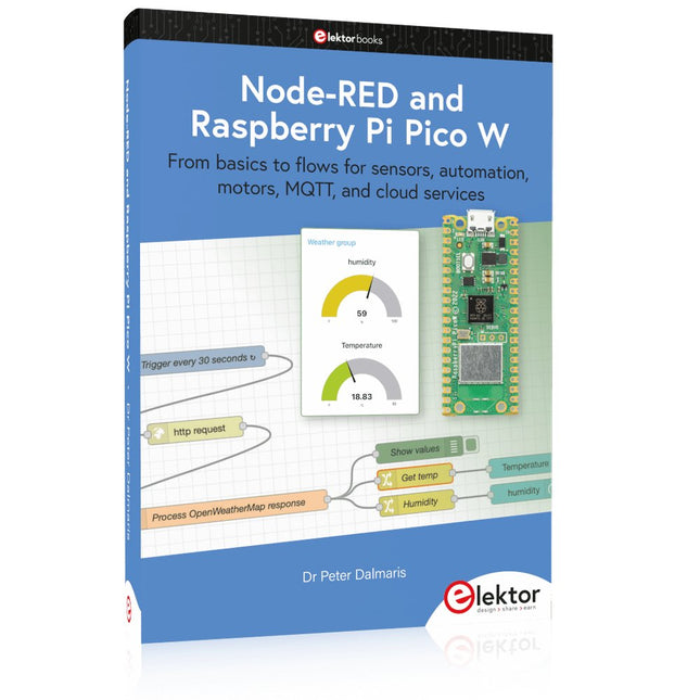
Elektor Publishing Node-RED and Raspberry Pi Pico W
From basics to flows for sensors, automation, motors, MQTT, and cloud services This book is a learning guide and a reference. Use it to learn Node-RED, Raspberry Pi Pico W, and MicroPython, and add these state-of-the-art tools to your technology toolkit. It will introduce you to virtual machines, Docker, and MySQL in support of IoT projects based on Node-RED and the Raspberry Pi Pico W. This book combines several elements into a platform that powers the development of modern Internet of Things applications. These elements are a flow-based server, a WiFi-enabled microcontroller, a high-level programming language, and a deployment technology. Combining these elements gives you the tools you need to create automation systems at any scale. From home automation to industrial automation, this book will help you get started. Node-RED is an open-source flow-based development tool that makes it easy to wire together devices, APIs, and online services. Drag and drop nodes to create a flowchart that turns on your lights at sunset or sends you an email when a sensor detects movement. Raspberry Pi Pico W is a version of the Raspberry Pi Pico with added 802.11n Wi-Fi capability. It is an ideal device for physical computing tasks and an excellent match to the Node-RED. Quick book facts Project-based learning approach. Assumes no prior knowledge of flow-based programming tools. Learn to use essential infrastructure tools in your projects, such as virtual machines, Docker, MySQL and useful web APIs such as Google Sheets and OpenWeatherMap. Dozens of mini-projects supported by photographs, wiring schematics, and source code. Get these from the book GitHub repository. Step-by-step instructions on everything. All experiments are based on the Raspberry Pi Pico W. A Wi-Fi network is required for all projects. Hardware (including the Raspberry Pi Pico W) is available as a kit. Downloads GitHub
€ 49,95
Members: € 44,96
-
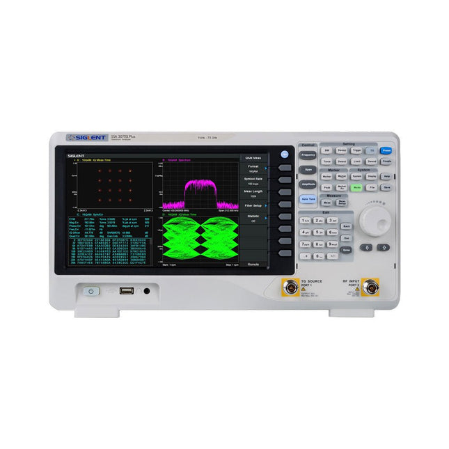
Siglent Siglent SSA3075X Plus Spectrum Analyzer (9 kHz – 7.5 GHz)
The Siglent SSA3075X Plus spectrum analyzer is a powerful and flexible tool for RF signal and network analysis. With a frequency range of 7.5 GHz, the analyzer delivers reliable automatic measurements and multiple modes of operation: spectrum analyzer the base, optional functions include RF power measurement, vector signal modulation analysis, reflection measurement, and EMI test. Applications include broadcast monitoring/evaluation, site surveying, S-parameter measurement, analog/digital modulation analysis, EMI pre-compliance test, research and development, education, production, and maintenance. Features Spectrum Analyzer Frequency Range from 9 kHz to 7.5 GHz –165 dBm/Hz Displayed Average Noise Level (Typ.) –98 dBc/Hz. @ 10 kHz Offset Phase Noise (1 GHz, Typ.) Level Measurement Uncertainty <0.7 dB (Typ.) 1 Hz Minimum Resolution Bandwidth (RBW) Preamplifier (Std.) Tracking Generator (incl. free of charge) Analog and Digital Signal Modulation Analysis Mode (opt.) Reflection Measurement Kit (opt.) EMI Filter and Quasi-Peak Detector Kit (opt.) Advanced Measurement Kit (opt.) 10.1-inch Multi-Touch Screen , Mouse and Keyboard supported Web Browser Remote Control on PC and Mobile Terminals and File Operation Specifications SSA3015X Plus SSA3021X Plus SSA3032X Plus SSA3075X Plus Frequency Range 9 kHz ~ 1.5 GHz 9 kHz ~ 2.1 GHz 9 kHz ~ 3.2 GHz 9 kHz ~ 7.5 GHz Resolution Bandwidth 1 Hz ~ 1 MHz 1 Hz ~ 1 MHz 1 Hz ~ 1 MHz 1 Hz ~ 3 MHz Phase Noise <–99 dBc/Hz <–98 dBc/Hz <–98 dBc/Hz <–98 dBc/Hz Total Amplitude Accuracy <1.2 dB <0.7 dB <0.7 dB <0.7 dB Display Average Noise Level –156 dBm/Hz –161 dBm/Hz –161 dBm/Hz –165 dBm/Hz Included Siglent SSA3075X Plus spectrum analyzer USB cable Power cord Quick start guide Downloads Datasheet Manual Documentation Firmware
€ 7.875,89
-

Siglent Siglent SDS1104X-E 4-ch Oscilloscope (100 MHz)
The Siglent SDS1104X-E employs a new generation of SPO (Super Phosphor Oscilloscope) technology that provides excellent signal fidelity and performance. The system noise is also lower than similar products in the industry. It comes with a minimum vertical input range of 500 uV/div, an innovative digital trigger system with high sensitivity and low jitter, and a waveform capture rate of 400,000 frames/sec (sequence mode). The SDS1104X-E also employs a 256-level intensity grading display function and a color temperature display mode not found in other models in this class. SIGLENT’s latest oscilloscopes offering supports multiple powerful triggering modes including serial bus triggering. Serial decoding is free and includes IIC, SPI, UART, CAN, and LIN. History waveform recording and sequential triggering enable extended waveform recording and analysis. Another powerful addition is the new 1 Mpt FFT math function that gives the SDS1104X-E very high frequency resolution when observing signal spectra. Features Intelligent trigger: Edge, Slope, Pulse Width, Window, Runt, Interval, Timeout (Dropout), and Pattern Free Serial bus triggering and decoding:IIC, SPI, UART, RS232, CAN, and LIN Video triggers and supports HDTV Low background noise and 500 μV / div to 10 V / div voltage scales 10 types of one-button shortcuts, supports Auto Setup, Default, Cursors, Measure, Roll, History, Display/Persist, Clear Sweep, Zoom and Print Segmented acquisition (Sequence) mode, dividing the maximum record length into multiple segments (up to 80,000), according to trigger conditions set by the user, with a very small dead time segment to capture the qualifying event. History waveform record (History) function, the maximum recorded waveform length is 80,000 frames Automatic measurement function on 38 parameters, supports Statistics, Gating measurement, Math measurement, History measurement and Ref measurement 1 Mpts FFT True measurement and math can use all 14 Mpts of memory Preset key can be customized for user settings or factory “defaults” Security Erase mode Highspeed hardware based Pass/ Fail function Large 7-inch TFT-LCD display with 800 * 480 resolution Multiple interface types: USB Host, USB Device (USB-TMC), LAN (VXI-11), Pass / Fail, Trigger Out Supports SCPI remote control commands Multi-language display and embedded help Browser control/onboard webpage for software free monitoring (4 channel models only) Included 1x Siglent SDS1104X-E Oscilloscope 4x 100 MHz probes 1x Guarantee Card 1x Power Cord 1x USB Cable 1x Quick Start Guide Downloads Datasheet Manual Programming Guide
€ 508,71
-
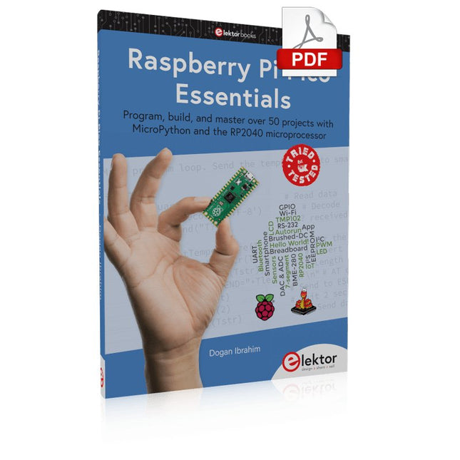
Elektor Digital Raspberry Pi Pico Essentials (E-book)
Program, build, and master over 50 projects with MicroPython and the RP2040 microprocessor The Raspberry Pi Pico is a high-performance microcontroller module designed especially for physical computing. Microcontrollers differ from single-board computers, like the Raspberry Pi 4, in not having an operating system. The Raspberry Pi Pico can be programmed to run a single task very efficiently within real-time control and monitoring applications requiring speed. The ‘Pico’ as we call it, is based on the fast, efficient, and low-cost dual-core ARM Cortex-M0+ RP2040 microcontroller chip running at up to 133 MHz and sporting 264 KB of SRAM, and 2 MB of Flash memory. Besides its large memory, the Pico has even more attractive features including a vast number of GPIO pins, and popular interface modules like ADC, SPI, I²C, UART, and PWM. To cap it all, the chip offers fast and accurate timing modules, a hardware debug interface, and an internal temperature sensor. The Raspberry Pi Pico is easily programmed using popular high-level languages such as MicroPython and or C/C++. This book is an introduction to using the Raspberry Pi Pico microcontroller in conjunction with the MicroPython programming language. The Thonny development environment (IDE) is used in all the projects described. There are over 50 working and tested projects in the book, covering the following topics: Installing the MicroPython on Raspberry Pi Pico using a Raspberry Pi or a PC Timer interrupts and external interrupts Analogue-to-digital converter (ADC) projects Using the internal temperature sensor and external temperature sensor chips Datalogging projects PWM, UART, I²C, and SPI projects Using Wi-Fi and apps to communicate with smartphones Using Bluetooth and apps to communicate with smartphones Digital-to-analogue converter (DAC) projects All projects given in the book have been fully tested and are working. Only basic programming and electronics experience is required to follow the projects. Brief descriptions, block diagrams, detailed circuit diagrams, and full MicroPython program listings are given for all projects described. Readers can find the program listings on the Elektor web page created to support the book.
€ 32,95
Members: € 29,66


