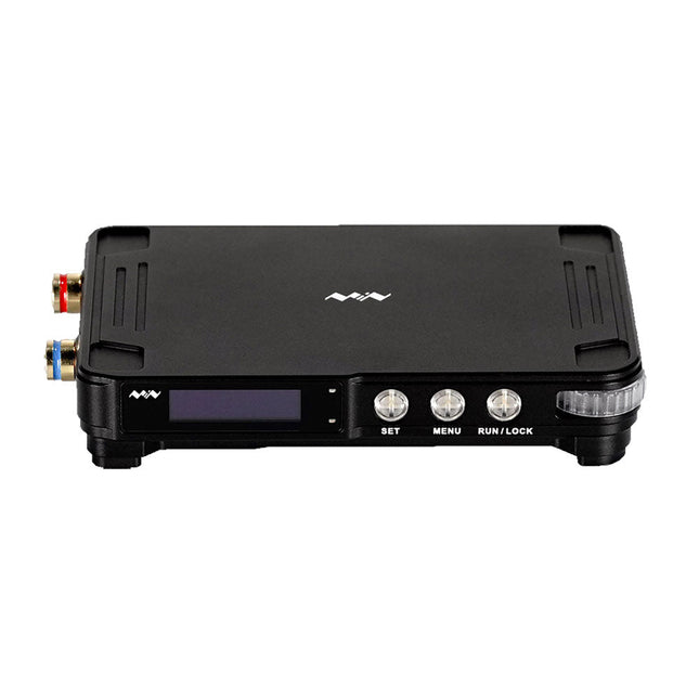
MDP-P906 has a built-in cooling fan, and maximum output power of up to 300 W, which meets a wider range of testing needs and application scenarios. Through 2.4 GHz wireless communication, it can be connected to MDP-M01 Smart Digital Monitor module to realize the free combination of multiple channels of 300 W per channel.
MDP-P906 has the index, stability and reliability comparable to a professional power supply. It can output pure current, and provide powerful functions such as programmable output, timing output, timing control, automatic compensation, boost mode, etc., making itself a real cost-effective, smart and customized programmable linear DC power supply.
MDP-P906 adopts a precision CNC machined aluminum alloy shell, with fine workmanship, novel, mini and beautiful appearance, it completely subverts the rigid image of traditional desktop power supply. With stackable modular design and wireless communication function, MDP-P906 can work independently or paired, both on the workbench, and be carried out for on-site maintenance. MDP-P906 is a perfect solution for electronic engineer, especially field application engineers to meet different needs of power sources.
Built-in silent cooling fan, instant cooling, ensure a stable and efficient output!
Smart linear compensation, constant voltage & constant current
Positive & negative output, series boost, parallel current sharing
Applications
Universal tests and teaching experiments in R&D laboratory
Maintenance of digital products
Property verification and fault diagnosis of devices and circuits
Emergency power supply for model airplanes and vehicles
Power supply testing of RF and microwave circuits or modules
Quality control and quality inspection
Supply purified power for high-accuracy digital-analog hybrid circuits and Hi-Fi audio devices
Specifications
Input
DC 4.2-30 V/14 A (Max)QC 3.0/PD2.0, 20 V/5 A (Max)
Output
0-30 V/0-10 A, 300 W (Max)
Conversion efficiency
95%
Output resolution
10 mV/2 mA, up to 1 mV/1 mA via Display Control module
Output accuracy
0.03%+5 mV0.05%+2 mV
Adjustment rate
Load adjustment rate <±0.01%Power adjustment rate <±0.01%
Ripple and noise
<250 uVrms, 3 mVpp; 2 mArms
Transient response
<4 uS
Safety protections
Input over-voltage, under-voltage, reverse connection protection, output over-current, back-flow protection and over-temperature protection
Others
Automatically shut-down and enter micro-power modeSupport USB firmware upgrade
Dimensions
112 x 66 x 20 mm
Weight
181 g
Included
1x MDP-P906 Digital Power Supply
2x Output Cable
1x User Manual
Downloads
User Manual v1.1
Firmware v1.32
Hands-on in more than 50 projects
STM32 Nucleo family of processors are manufactured by STMicroelectronics. These are low-cost ARM microcontroller development boards. This book is about developing projects using the popular STM32CubeIDE software with the Nucleo-L476RG development board. In the early Chapters of the book the architecture of the Nucleo family is briefly described.
The book covers many projects using most features of the Nucleo-L476RG development board where the full software listings for the STM32CubeIDE are given for each project together with extensive descriptions. The projects range from simple flashing LEDs to more complex projects using modules, devices, and libraries such as GPIO, ADC, DAC, I²C, SPI, LCD, DMA, analogue inputs, power management, X-CUBE-MEMS1 library, DEBUGGING, and others. In addition, several projects are given using the popular Nucleo Expansion Boards. These Expansion Boards plug on top of the Nucleo development boards and provide sensors, relays, accelerometers, gyroscopes, Wi-Fi, and many others. Using an expansion board together with the X-CUBE-MEMS1 library simplifies the task of project development considerably.
All the projects in the book have been tested and are working. The following sub-headings are given for each project: Project Title, Description, Aim, Block Diagram, Circuit Diagram, and Program Listing for the STM32CubeIDE.
In this book you will learn about
STM32 microcontroller architecture;
the Nucleo-L476RG development board in projects using the STM32CubeIDE integrated software development tool;
external and internal interrupts and DMA;
DEBUG, a program developed using the STM32CubeIDE;
the MCU in Sleep, Stop, and in Standby modes;
Nucleo Expansion Boards with the Nucleo development boards.
What you need
a PC with Internet connection and a USB port;
STM32CubeIDE software (available at STMicroelectronics website free of charge)
the project source files, available from the book’s webpage hosted by Elektor;
Nucleo-L476RG development board;
simple electronic devices such as LEDs, temperature sensor, I²C and SPI chips, and a few more;
Nucleo Expansion Boards (optional).
electronica fast forward Start- & Scale-Up Awardsde voorbereidingen gaan steeds sneller!
Bluetooth Low Energy met ESP32-C3 en ESP32het hoeft niet altijd WiFi te zijn!
Bluetooth LE-snifferhack een makerdiary nRF52840 MDK USB-dongle
Magische RGB LED-kubushardware ontwerpen rond een RP2040 Auto-aan/uit voor soldeerpasta-compressor
Elektor video-productieslivestreams, webinars en cursussen voor engineers en pro-makers
Elektrificeer je fietsmet een e-bike ombouwset
Alle begin......vermenigvuldigt spanningen
Uit het leven gegrepennevenactiviteiten
Teensy 4.0 – waarom is dat board zo snel?snelheid is geen hekserij!
Simulatie van een audio-eindversterker met TINAeerst uitproberen, dan bouwen
Ontwikkel en beheer je eigen LoRaWAN IoT-nodesvoorbeeldhoofdstuk: Dragino LHT65, LDS01 en LDS02 LoRaWAN modules
Project 2.0correcties, updates en brieven van lezers
5G – alleen voor mijvolledige controle over 5G-implementaties met een eigen cellulair netwerk Elektor Infographics
Tips voor het ontwikkelen van een WiFi-interfacetoepassingen uitrusten met WiFi-interfaces Rijntoren-klok Mk 2
Audio-spectrumanalyzer met dekatronsnieuw leven voor vintage-buisjes
Data naar Telegram sturenmet een ESP32 en een paar onderdelen
Een Fliege-notchfilter voor audiometingenmeet beter met een notchfilter
Veranderende industriële communicatieSingle Pair Ethernet – meer dan zo maar een nieuwe connector
Elektronische mannetjes-PUT-terzo werkt de programmeerbare unijunctie-transistor
Rond touchscreen voor Raspberry PiHyperPixel 2.1 Round van Pimoroni
Remote sensing met detectie van verbindingsverliesmet nRF24L01+ modules
Digitale FM-ontvanger met Arduino en TEA5767stem af met een Arduino Nano OLED-interface ombouwen van SPI naar I²C
Oost West Lab Besteen hobby gaat niet met pensioen...
Tien jaar ethiek in elektronicaTessel Renzenbrink over de digitale samenleving en meer
HexadokuThe Original Elektorized Sudok
Elektor GREEN en GOLD leden kunnen deze uitgave hier downloaden.Nog geen lid? Klik hier om een lidmaatschap af te sluiten.
Raspberry Pi Pico als spectrumanalyzerFFT’s met goedkope hardware
±40 V lineaire spanningsregelaaralternatieve voeding voor de Fortissimo-100 eindversterker... en andere!
Flexibele draadloze communicatie met een MCUEEPROM opent netwerkmogelijkheden voor draadloze MCU’s
€ 5000 voor het oprapen!doe mee aan de STM32 Wireless Innovation Design Contest
2023: een AI-odysseeaan de slag met Code Interpreter van ChatGPT
LoRa – een Zwitsers zakmesdeel 1: het LoRa-protocol en zijn voordelen
Instelbare current sink met geïntegreerde klokgeneratortest voedingen, spanningsconverters en accu’s
Twee nieuwe Arduino UNO R4-boards: Minima en WiFi
Logaritmische potentiometersze zijn exponentieel!
Motordriver breakout-boardeen BoB voor een 5 A DC-motordriver van 3×3 mm
Uit het leven gegrepenelektronica periculosa
Biedt cellulair het laagste stroomverbruik voor IoT?energie-eisen van LTE-M en NB-IoT in LPWAN-implementaties
Draadloze communicatie in IoT-systemen met Arduino MKR-moduleshet juiste board voor WiFi, LoRa en andere standaarden
AC-verliezen in magnetische componentenvoorkom hete spoelen!
Meten voor optimale cloud-connectiviteit
Matter implementatie: Wat is er nodig om Matter-devices in te zetten?
YARD Stick Onesub-1 GHz draadloos testtool
Houdrelaisvreemde onderdelen
PIC voor tien – precies op tijdontwerp van een SDR-tijdseinontvanger
Due Diligence DirectiveBusiness as Usual Will Not Do
Alle begin......versterkt spanningen
Infrageluid-recorder met de Arduino Pro Minieen voorbeeldproject uit de Elektor-uitgave “Arduino & Co”
Cloud-gebaseerde energiemetermet een ESP32-module en een PZEM-004T spanning/stroom-sensor
Een gids voor puristisch programmeren (deel 2)nauwkeurige timing, de UART en debugging
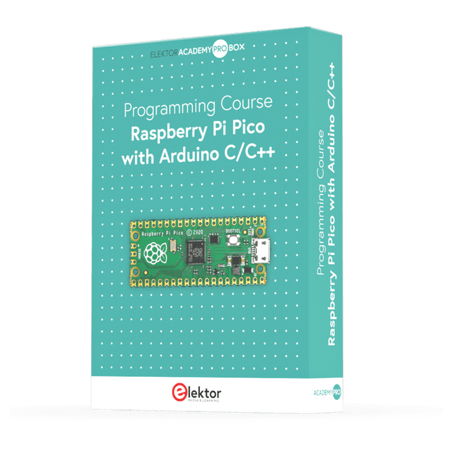
This complete Raspberry Pi Pico microcontroller programming course features a textbook, a component kit, hands-on projects, and a comprehensive online course with simulations. It is ideal for step-by-step learning of embedded systems programming with Arduino using a practical, hands-on approach.
A Practical Introduction to Embedded Systems with the Raspberry Pi Pico
This course is designed for people who are new to embedded systems and looking for a structured, example-driven way to get started.
A kit of parts comprising LEDs and resistors, switches, sensors and actuators, displays, a breadboard and wires, and more is included. These are used in the course to illustrate example applications.
No prior experience with Arduino or embedded development is required. Each section features hands-on examples and mini projects designed to reinforce key concepts and inspire deeper exploration. By the end of the course, you’ll be able not only to reproduce the examples but also to build on them with your own ideas and applications.
What Will You Learn?
Microcontroller programming in C/C++ with the Raspberry Pi Pico using the Arduino IDE
Working with Digital I/O, read buttons and encoders, control LEDs and relays
Read analog inputs, voltages, and analog sensors
Generating analog output signals and PWM
Use serial communication like UART, I²C and SPI to control displays and read digital sensors and SD cards
Managing time
Working with interrupts
Real-time sensor input and control via buttons, LEDs, and displays
Control actuators like relays and servo motors
Who Is It For?
Students and self-learners exploring embedded systems
Makers and IoT enthusiasts looking to improve their hardware skills
Educators and trainers seeking ready-to-teach material
What's Inside the Box?
Access to the full course on the Elektor Academy Pro Learning Platform
Raspberry Pi Pico microcontroller board + USB cable
Book: Programming Microcontrollers in C/C++ Using Arduino
Downloadable project files for every module
Component Box:
2× LED, red, 5 mm
LED, green, 5 mm
3× Resistor, 470 Ω, 0.25 W
LDR
Potentiometer, 10 kΩ, linear
Pushbutton
Rotary encoder module
Relay module
DHT22 Humidity & Temperature Sensor
TM1637-compatible 4-digit 7-segment display
MPU-6050 IMU with headers
SSD1306-compatible I²C OLED display
Micro SD card adapter with header
Buzzer
SG90 Micro Servo
ILI9341-compatible SPI 240×320 TFT display
20× Jumper wires
Breadboard
All Programming Courses (and differences in content)
Course
Arduino
Raspberry Pi Pico with Arduino C/C++
ESP32 with Arduino C/C++
Raspberry Pi Pico with MicroPython
ESP32 with MicroPython
Online Course
Access to Arduino Course
Access to Pico with Arduino C/C++ Course
Access to ESP32 with Arduino C/C++ Course
Access to Pico with MicroPython Course
Access to ESP32 with MicroPython Course
Board
Uno R3
Raspberry Pi Pico
ESP32
Raspberry Pi Pico
ESP32
Book
Programming Microcontrollers in C/C++ Using Arduino
Programming Microcontrollers in C/C++ Using Arduino
Programming Microcontrollers in C/C++ Using Arduino
Programming Microcontrollers in MicroPython
Programming Microcontrollers in MicroPython
Kit
40-piece Component Box
40-piece Component Box
40-piece Component Box
40-piece Component Box
40-piece Component Box
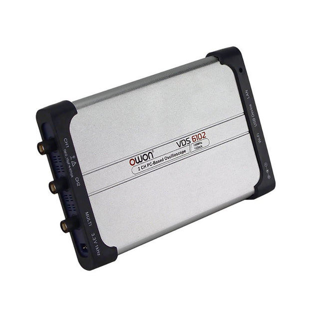
The OWON VDS6000 Series PC Oscilloscope combines powerful performance with a sleek, ultra-thin design. With 100 MHz bandwidth, 1 GSa/s real-time sampling, and up to 14-bit resolution, it delivers highly accurate measurements. The built-in 5 MHz function generator, USB-C power supply, and optional WiFi connectivity make it incredibly versatile.
Compatible with Windows, Linux, Android, and iOS, the VDS6000 is perfect for labs, fieldwork, and remote diagnostics – compact, flexible, and ready for any challenge.
Features
Bandwidth: 100 MHz
Vertical resolution: 14 bits
Rise time: ≤3.5 ns
Memory: 10 Mpts
Number of channels: 2 channels + 1 channel function generator
Horizontal scale: 5ns - 100s/div
Sample rate: Max. 1 GSa/s
Maximum voltage: 40 V (peak - peak)
Automatic measurements: Vpp, Vavg, Vamp, Vrms, Freq, Period, Vmax, Vmin, Vtop, Vbase, Overshoot, Preshoot, Rise Time,
Connectivity: USB-C, LAN, Wifi (optional)
Fall Time, Delay A→B↑, Delay A→B↓, +Width, -Width, +Duty, -Duty
Bandwidth: 5 MHz
Sample rate: 25 MSa/s
Standard waveforms: Sine (0.1 Hz - 5 MHz), Square (0.1 Hz - 200 kHz), Ramp (1 Hz - 10 kHz), Pulse (1 Hz - 10 kHz)
Resolution: 10 bits
DC offset range (AC + DC): ±2.5 V
Amplitude range: 10 mVpp - 5 Vpp
Dimensions: 190 x 120 x 18 mm
Weight: 380 g
Downloads
Manual
Quick Guide
PC Software
MacOS Software
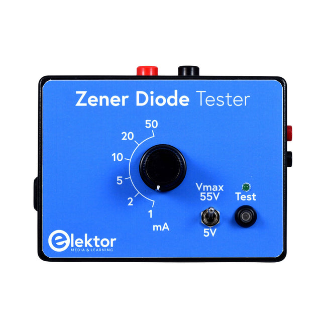
The Elektor Zener Diode Tester is essentially a constant-current source that can be switched in steps from 1 to 50 mA. It can be used to test Z-diodes up to a maximum of 54 V. Thanks to a 60-V step-up converter, the device can be powered by the usual 5 to 12 V.
The principle of this tester is straightforward. A Z-diode or other DUT (device under test, such as an LED) is biased by an adjustable current source. The voltage across the DUT can be measured with a multimeter. The voltage of most (small) Z-diodes is specified at a current of 5 mA. Depending on the application, the voltage at other currents can also be of interest. That is why six current settings are available: 1, 2, 5, 10, 20, and 50 mA. LEDs are often specified at a current of 20 mA.
What can be tested is:
Whether a Z-diode is defective (short circuit or high impedance).
Whether a Z-diode exhibits the correct Z-voltage.
How a Z-voltage changes with different currents.
What exact voltage is present at an integrated voltage reference.
Whether LEDs in a series chain differ in brightness (hence the 20 mA current).
What the current gain is for different base currents in (power) transistors.
The kit contains all parts listed in the bill of materials including PCB and enclosure.
Specifications
Supply voltage
5…12 V/2 A (USB-C)
Supply current (Itest = 50 mA)
1.1 A @ 5 V / 412 mA @ 12 V
Selectable currents
1, 2, 5, 10, 20, and 50 mA
Max. test voltage
>54 V @ Itest ≥1 mA
Max. output voltage
60 V @ Itest = 0 mA
Voltage limit at 5 V
4.5 V @ Itest = 1 mA / 5.18 V @ Itest = 50 mA
Enclosure dimensions
110 x 82 x 44 mm
PCB size
105.4 x 67.3 mm
Connections
4 mm banana sockets for multimeter
2 mm banana sockets for test clips
USB-C socket for power supply
Included
Resistors
R1 = 3.3 kΩ, 600 mW, 1%
R2 = 0.15 Ω, 1 W, 5%, LS 12.7 mm, ø 3.5 mm
R3, R8 = 180 Ω, 600 mW, 1%
R4, R6, R16 = 1 kΩ, 600 mW, 1%
R5, R19 = 47 kΩ, 600 mW, 1%
R7 = 3.9 kΩ, 1 W, 5%, LS 12.7 mm, ø 3.5 mm
R9, R10, R12 = 10 kΩ, 600 mW, 1%
R11, R13 = 100 Ω, 600 mW 1%
R14 = 249 Ω, 600 mW, 1%
R15 = 499 Ω, 600 mW, 1%
R17 = 2.49 kΩ, 250 mW, 1%
R18 = 4.99 kΩ, 250 mW, 1%
Capacitors
C1 = 470 uF / 35 V, 20%, Ir = 1.86 A, ø 12.5 mm, LS 5 mm, ESR = 0.038 Ω (Panasonic EEUTP1V471)
C2 = 1 uF / 100 V, 10%, X7R, LS 5 mm
C3 = 2.2 nF / 50 V, 10%, X7R, LS 5 mm
C4, C7 = 100 nF / 100 V, 10%, X7R, LS 5 mm
C5 = 100 uF / 100 V, 20%, ø 14 mm max., LS 5 mm
C6 = 1 nF / 100 V, 10%, X7R, LS 5 mm
Inductor
L1 = 100 uH, Irms = 2.4 A, Isat = 3.5 A, 0.09 Ω, radial, pitch 2.5/5/10 mm, ø 14 mm max. (Kemet SBC8-101-242)
Semiconductors
D1 = MUR120G, DO-41
D2, D4 = STPS3150RL, DO-201AD
D3 = Z-diode, 18 V, 1.3 W (BZX85C18)
D5 = Z-diode, 5.1 V, 0.5 W (1N5231B)
LED1 = LED in pushbutton S1
LED2 = LED, green, 3 mm
IC1 = MC34063, DIP-8
IC2 = LM4040BIZ-5.0/NOPB, TO-92 (TO-226AA-3)
IC3 = TL051CP, DIP-8
T1 = BC327.25, TO-92
T2 = STP40NF10L, TO-220
T3 = IRF9510PBF, TO-220
T4 = 2N7000, TO-92
Others
K1, K2, S1, S3 = 2-way screw terminal block, LS 3.5 mm, max. 1.5 mm²
connected to K1 = USB-C socket, 30 V/3 A, chassis mounted, wired, 9 x 16 mm
connected to K2 = Banana Connector, 2 mm, Socket, 60 VDC, Panel Mount, red (Multicomp 24.102.1)
connected to K2 = Banana Connector, 2 mm, Socket, 60 VDC, Panel Mount, black (Multicomp 24.102.2)
Test clip, red, 30 VAC/60 VDC (Hirschmann 931467101)
Test clip, black, 30 VAC/60 VDC (Hirschmann 931467100)
S1 = Pushbutton, panel mount, SPST-NO, 30 DC/100 mA, with red LED
S2 = Rotary Switch, 6 position, 2 pole, 30°, 250 V/150 mA
S3 = Toggle switch, panel mount, SPDT, solder lugs, 28 VDC
T2, T3 = Heat sink, 15°C/W, FK 214 SA-CB
Enclosure Hammond 1591XXSSBK, ABS, 110 x 82 x 44 mm
Knob for S2, round shaft 6 mm, ø 21 mm, with indicator line (Multicomp CP-LB21-6-6D)
4 x Self-tapping screw #4-1/4", carbon steel, pan head
Banana plug, red, 2 mm, 60 VDC (Multicomp 25.205.1)
Banana plug, black, 2 mm, 60 VDC (Multicomp 25.205.2)
Banana socket, black 4 mm, panel mount
Banana socket, red 4 mm, panel mount
for LED1, LED2 = Pin header, 1 x 2, vertical, pitch 2.54 mm
for LED1, LED2 = Pin socket, 1 x 2, vertical, pitch 2.54 mm
for T2, T3 = M3 screw, 10 mm, steel, pan head
2 x M3 washer, plain, steel
4 x M3 nut
for IC1, IC3 = DIP-8 socket
Wire, black, 0.25 mm² (24 AWG), stranded 14 x 0.15 mm, 1 m
Wire, red, 0.25 mm² (24 AWG), stranded 14 x 0.15 mm, 1 m
PCB 250772-1 v1.1
Links
Article
Elektor Labs
The OWON SDS1102 is an affordable benchtop digital oscilloscope that combines solid performance with essential measurement features. This 2-channel oscilloscope offers a 100 MHz bandwidth, a 1 GS/s sampling rate, a 7-inch LCD display, and a 10 kpts memory depth, making it a practical choice for everyday electronics testing, troubleshooting, and education.
The SDS1102 features a simplified trigger system with level and edge triggering, making it easy to capture and analyze common signals. It is designed for applications that do not require deep memory or advanced trigger functions, offering a straightforward and cost-effective solution for basic signal analysis.
Features
Bandwidth: 100 MHz
2 channels
Sample rate: 1 GS/s
Ultra-thin body
7-inch high-res LCD
SCPI and LabVIEW supported
Specifications
Bandwidth
100 MHz
Horizontal Scale (s/div)
5 ns/div – 1000 s/div
Channel
2
Vertical Sensitivity
5 mV/div – 5 V/div (at input)
DC Gain Accuracy
3%
Vertical Resolution (A/D)
8 bits (2 channels simultaneously)
Input
Input Impedance
1 MΩ, 10 pF
Input Coupling
AC, DC, GND
Max Input Voltage
±400 V, CATI, CATII
Passive probes
х1; х10
Probe Attenuation Factor
х1; х10; х100; х1000
Trigger System
Trigger Mode
Auto, Normal, Single
Trigger Type
Edge, Video
Edge Trigger Source
CH1, CH2
Video Trigger
Sampling Type
Real-time
Sample Rate
1 GS/s
Equivalent Sample Rate
No
Wavelength
10K pts
Interpolation
sin(x)/x
Measurement and Mathematical Treatment System
Automatic Measurement
Vpp, Vavg, RMS, Frequency, Period, Vmax, Vmin, Vtop, Vbase, Width, Overshoot, Pre-shootRise time, Fall time, +Width, -Width, +Duty, -Duty, Delay A→B, Delay A→B, area, cycle area
Math Functions
Addition, Subtraction, Multiplication, Division, FFT
General Characteristics
Display type
7" color LCD
Display Resolution
800 x 480
Power
100-240 V, 45-440 Hz, <15 W
Dimensions
301 x 70 x 152 mm
Weight
1.1 kg
Included
1x OWON SDS1102 Oscilloscope
2x Oscilloscope probes
1x Probe adjust
1x Mains power cord
1x USB cable
1x CD-Rom
1x Quick guide
Downloads
Quick Guide
Manual
PC Software
SCPI Commands
Le téléchargement intégral de ce numéro est disponible pour nos membres GOLD et GREEN sur le site Elektor Magazine !
Pas encore membre ? Cliquez ici.
L'architecture de processeur open-source RISC-V16 cartes et MCU à connaître
un lecteur audio avec égaliseur basé sur un FPGAMixage audio numérique avec un Arduino MKR Vidor 4000
tête laser pour l’horloge de sable basé sur Raspberry Pi PicoDessiner avec la lumière
participez au concours STM32 Edge AI
système de contrôle environnemental multi-capteurs pour les plantesMesure sans fil de l'approvisionnement en eau et de la luminosité
porte automatique contrôlée par l'IA et MaixduinoReconnaissance faciale avec une caméra
l’électronique embarquée en 2024L’IA va redéfinir l’industrie
Calcul en mémoire basé sur la charge chez EnCharge AI
des opérations d'IA avec 10 fois moins d'énergie et des coûts divisés par 20
Une carte pour le développement et l’entraînement des modèles ML d’analyse des vibrations
Elektor Mini-WheelieKit robot gyropode (robot autostabilisé)
MCUViewerMCUViewer outil de débogage open source multiplateforme
isolateur USB 2.0Isolation éléctrique pour les périphériques USB
anticipation et actionApplication pratique de la maintenance prédictive
SPoE – compatibilité électromagnétiquePaire unique avec Power-over-Ethernet à travers les yeux d'EMC
rétro-techCréer un monde nouveau avec la télévision couleur
surveillance ECGavec des modules Hexabitz et STM32CubeMonitor
la bataille pour l’IA en périphérie
HaLow atteint une distance Wifi record de 16 km à 900 MHz
première puce embarquée CHERI RISC-V et programme d'accès anticipé
la détection des incendies de forêt de troisième génération utilise des liaisons satellites
sur le vifDélices et supplices du choix
démarrer en électronique......Filtrage et contrôle de la tonalité
Kit d'horloge quasi-analogiqueNouvelle version d'un classique d'Elektor
une approche modulaire de test des capteursCarte de test de capteurs basée sur l'ESP32-S3
2025 : une odyssée de l'IAL'essor des modèles de fondation et leur impact sur l'accessibilité de l'IA
Synthétiseur MIDI autonome Raspberry Pi (1)Préparation d'une plateforme pour des expériences d’IA en périphérie
projet 2.0Corrections, mises à jour et courrier des lecteurs
Le RISC-V AI, un processeur à tout faire : CPU, GPU, DSP, FPGA
paroles de PDG : fraîcheur, silence et finesse
programmation Dual-Core avec le Raspberry Pi PicoLe monde de la programmation parallèle
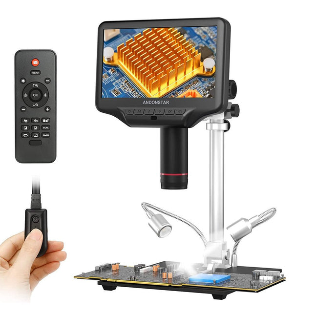
The Andonstar ADSM302 is a versatile digital microscope with an integrated 5-inch LCD display and HDMI output for crystal-clear views in Full HD (1080p). With a 3-megapixel sensor, up to ~560x magnification, and two adjustable LED lights, it reveals the finest details – ideal for PCB inspections, soldering work, jewelry or insect analysis.
Features
5" adjustable LCD monitor with adjustable tilt angle
High resolution video & photo capture
Wide table with comfortable headroom
Heavy-weight stable metal stand
Tall lifting stand (26 cm)
Smooth adjustment wheels for focus and height
Buttons on the monitor + remote control
AV, USB, HDMI outputs
SD card storage <32 GB
Specifications
Image sensor
3 Megapixels HD Sensor
Video output
1080p Full HD (via HDMI)720p (via PC)
Video format
Real time play via HDMI w/o recordingMJPEG recording via PC/Mac Software
Magnification
Up to 560 times (HDMI monitor 22")
Photo resolution
12M (see pixel formats in following table)
Photo format
JPEG
Focus range
5 to 22 cm
Frame rate
Up to 30 f/s under 600 Lux Brightness
Video-output interface
HDMI/AV
Storage
microSD card, up to 32 GB
PC support
Windows XP/7/8/10PC software with measurementMacOS successfully tested under OSX with OBSsee video below
Power source
5 V DC
Light source
2x LED with the stand
Screen size
5 inch (12.7 cm)
Stand size
20 x 12 x 26.5 cm
Resolution
Captured Photos
4032 x 3024
3648 x 2736
3264 x 2448
2592 x 1944
2048 x 1536
640 x 480
1920 x 1080
1280 x 960
1280 x 720*
Videos
1920 x 1080
640 x 480*
* (USB with software)
Included
1x Andonstar ADSM302 digital microscope
1x Metal stand with 2 LEDs
1x USB cable
1x HDMI cable
1x Adapter
1x AI remote
1x Instructions
Downloads
Manual
Software
The Andonstar AD407 Pro microscope is suitable for various applications such as soldering SMDs or repair work. The microscope has a large adjustable 7" LCD display and comes with a remote. Compared to AD407, AD407 Pro offers an extra-high stand, which makes soldering of components even easier.
Specifications
Screen size
7 inch (17.8 cm)
Image sensor
4 MP
Video output
UHD 2880x2160 (24fps)FHD 1920x1080 (60fps/30fps)HD 1280x720 (120fps)
Video format
MP4
Magnification
Up to 270 times (27 inch HDMI monitor)
Photo resolution
Max. 12 MP (4032x3024)
Photo format
JPG
Focus range
Min. 5 cm
Frame Rate
Max. 120fps
Video interface
HDMI
Storage
microSD card (up to 64 GB)
Power source
5 V DC
Light source
2 LEDs with the stand
Stand size
20 x 18 x 32 cm
Included
1x Andonstar AD407 Pro Digital Microscope
1x Metal stand with 2 LEDs
1x UV filter (already assembled in the lens)
1x IR remote
1x Switch cable
1x Power adapter
1x Wrench
2x Metal clips
1x HDMI cable
1x Manual
Downloads
Manual
Model Comparison
AD407
AD407 Pro
AD409
AD409 Pro-ES
Screen size
7 inch (17.8 cm)
7 inch (17.8 cm)
10.1 inch (25.7 cm)
10.1 inch (25.7 cm)
Image sensor
4 MP
4 MP
4 MP
4 MP
Video output
2160p
2160p
2160p
2160p
Interfaces
HDMI
HDMI
USB, HDMI, WiFi
USB, HDMI, WiFi
Video format
MP4
MP4
MP4
MP4
Magnification
Up to 270x
Up to 270x
Up to 300x
Up to 300x
Photo resolution
Max. 4032x3024
Max. 4032x3024
Max. 4032x3024
Max. 4032x3024
Photo format
JPG
JPG
JPG
JPG
Focus distance
Min. 5 cm
Min. 5 cm
Min. 5 cm
Min. 5 cm
Frame rate
Max. 120f/s
Max. 120f/s
Max. 120f/s
Max. 120f/s
Storage
microSD card
microSD card
microSD card
microSD card
PC support
No
No
Windows
Windows
Mobile connection
No
No
WiFi + Measurement
WiFi + Measurement
Power source
5 V DC
5 V DC
5 V DC
5 V DC
Light source
2 LEDs with the stand
2 LEDs with the stand
2 LEDs with the stand
2 LEDs with the stand
Endoscope
No
No
No
Yes
Stand size
20 x 12 x 19 cm
20 x 18 x 32 cm
18 x 20 x 30 cm
18 x 20 x 32 cm
Weight
1.6 kg
2.1 kg
2.2 kg
2.5 kg
This book is all about building your own DIY home control system. It presents two innovative ways to assemble such a system: By recycling old PC hardware – possibly extending the life of an old PC, or by using Raspberry Pi. In both cases, the main system outlined in this book will consist of a computer platform, a wireless mains outlet, a controller and a USB webcam – All linked together by Linux.
By using the Raspberry Pi in conjunction with Arduino (used as an advanced I/O system board), it is possible to construct a small, compact, embedded control system offering enhanced capacity for USB integration, webcams, thermal monitoring and communication with the outside world.
The experience required to undertake the projects within this book are minimal exposure to PC hardware and software, the ability to surf the internet, burn a CD-ROM and assemble a small PCB.