Master digital electronics – the hands-on way!
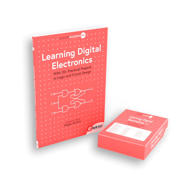
This bundle includes the book Learning Digital Electronics, featuring 20+ practical projects in Logic and Circuit design, as well as a 100-piece kit – so you can start building logic circuits, counters, displays, and more right away.
Learning Digital Electronics (Book)
This book is a practical guide to digital electronics, covering the essential components of modern digital systems: number systems, logic gates, Boolean algebra, combinational and sequential logic, and more.
Through more than 20 structured projects, you’ll design and build digital systems using real-world components such as logic gates, multiplexers, decoders, flip-flops, counters, and shift registers. The projects range from basic LED logic circuits to digital locks, display systems, traffic light controllers, and timing-based designs.
Selected projects introduce the use of tools such as CircuitVerse for circuit simulation, while several designs make use of 74HC-series logic devices, commonly used in digital hardware prototyping.
Inside, you’ll find:
Clear coverage of number systems and binary arithmetic
Logic gate fundamentals and universal gate implementations
Step-by-step projects using flip-flops, counters, and registers
Real-world design with 74HC-series logic chips
Techniques for designing combinational and sequential systems
This book takes a design-first, application-driven approach to digital electronics—built around working circuits, tested logic, and hands-on experimentation.
Learning Digital Electronics (Kit)
This kit has been specially developed to complement the book "Learning Digital Electronics". Since all necessary components are included, you can complete every practical project in the book directly.
Kit contents
2x 74HC08 AND gate chip
2x 74HC00 NAND gate chip
1x 74HC86 XOR gate chip
1x 555 timer chip
1x 74HC161 counter chip
1x 74HC164 shift register
1x CD4511 7-segment decoder
1x CD4027 JK flip-flop
1x BC337 NPN transistor
1x KPS-5161 7-segment common-cathode display
1x Light dependent resistor (LDR)
4x 10 KΩ resistors
8x 1 KΩ resistor
2x 47 KΩ resistors
1x 100 KΩ resistor
4x 2.7 KΩ resistors
1x 5.6 KΩ resistor
1x 150 KΩ resistor
1x 10 μF capacitor
2x 0.01 μF capacitor
2x 100 nF capacitor
8x Small red LED
1x Small green LED
1x Small orange LED
4x Pushbutton switches
1x Active buzzer
1x Battery holder for 3x AA batteries (batteries not included)
1x Breadboard
40x Male-to-male jumper wires (length: 200 mm)
The FNIRSI TMP-610S is a compact 3-in-1 test instrument combining a True RMS multimeter, 10 MHz oscilloscope, and 50 kHz DDS signal generator. It is designed for electronics troubleshooting, circuit testing, and development in the lab or on the go.
The multimeter offers 60,000-count resolution and supports voltage, current, resistance, capacitance, frequency, temperature, diode, and continuity measurements. The integrated oscilloscope provides real-time waveform analysis at up to 48 MSa/s, while the signal generator supports 13 waveform types with adjustable frequency, amplitude, and duty cycle.
A 3.5-inch IPS touchscreen, smart auto-scan, Bluetooth connectivity for DMM functions, waveform storage, USB export, and a 3,000 mAh rechargeable battery make the TMP-610S a versatile all-in-one tool for electronics professionals and enthusiasts.
Features
3-in-1 Design: DMM + Oscilloscope + Signal Generator
60,000-Count True RMS High-Precision Measurement
10 MHz Oscilloscope with 48 MSa/s Sampling Rate
Bluetooth App Sync (Multimeter Function Only)
3.5-inch Smart Touchscreen with Multiple Display Modes
50 kHz DDS Signal Generator with 13 Waveforms
Built-in Fuse for Easy Replacement
Specifications
Multimeter
Function
Range
Accuracy
DC voltage
600mV/6V/60V/600V/1000V
±(0.03%+5d)
AC voltage
600mV/6V/60V /600V/750V
±(0.3%+15d)
DC current
600uA/6000uA/60mA/600mA
±(0.15%+5d)
6A/10A
±(0.2%+5d)
AC current
600uA/6000uA/60mA/600mA
±(0.5%+15d)
6A/10A
±(0.75%+15d)
Resistance
600Ω/6KΩ/60KΩ/600KΩ/6MΩ
±(0.1%+5d)
60MΩ
±(0.2%+10d)
Capacitance
60nF/600nF/6uF/60uF
±(2.5%+30d)
600uF/6mF/60mF
±(3.5%+30d
Frequency
10 Hz~60 MHz
±(0.01%+5d)
Temperature
-40℃~1000℃
±(1.0%+5℃)
Continuity
0Ω~1KΩ
±(0.2%+5d)
Diode
0V~3.0V, 0Ω~1 Ω
±(1%+5d)
AC frequency response
10KHz
/
Oscilloscope
Real-time Sampling Rate
48 MSa/s
Analog Bandwidth
10 MHz
Input Impedance
1MΩ
Coupling Mode
AC/DC
Test Voltage Range
1:1 Probe - 80Vpp (±40V)
10:1 Probe - 800Vpp (±400V)
Vertical Sensitivity
10mV/div~10V/div
Vertical Displacement
Adjustable with indication
Horizontal Time Base Range
50 ns ~ 20 s
Trigger Mode
Auto, Normal, Single
Trigger Type
Rising, Falling, 50%
Trigger Level
Adjustable with indication
Measurement Parameters
Freq, Period, +Duty, ‒Duty, +Width, ‒Width, Max, Min, P‒P, Amp, RMS, Avg
Persistence
Off / 500ms / 1s / ∞
Cursor Measurement
Yes
Waveform Screenshot Saving
Yes
Signal Generator
Output Waveform
Supports 13 waveform types
Frequency
0~50kHz
Amplitude
0.0V~3.0V
Duty Cycle
0~100%, adjustable for Square and Sawtooth waves
Included
1x FNIRSI TMP-610S Multimeter + Oscilloscope + Signal Generator
1x P6100 Probe
1x Adapter
2x Alligator Clips
2x Multimeter Probes
Probe Accessories
1x Storage Bag
1x USB-C Cable
1x Manual
Downloads
Manual
The OWON SDS1102 is an affordable benchtop digital oscilloscope that combines solid performance with essential measurement features. This 2-channel oscilloscope offers a 100 MHz bandwidth, a 1 GS/s sampling rate, a 7-inch LCD display, and a 10 kpts memory depth, making it a practical choice for everyday electronics testing, troubleshooting, and education.
The SDS1102 features a simplified trigger system with level and edge triggering, making it easy to capture and analyze common signals. It is designed for applications that do not require deep memory or advanced trigger functions, offering a straightforward and cost-effective solution for basic signal analysis.
Features
Bandwidth: 100 MHz
2 channels
Sample rate: 1 GS/s
Ultra-thin body
7-inch high-res LCD
SCPI and LabVIEW supported
Specifications
Bandwidth
100 MHz
Horizontal Scale (s/div)
5 ns/div – 1000 s/div
Channel
2
Vertical Sensitivity
5 mV/div – 5 V/div (at input)
DC Gain Accuracy
3%
Vertical Resolution (A/D)
8 bits (2 channels simultaneously)
Input
Input Impedance
1 MΩ, 10 pF
Input Coupling
AC, DC, GND
Max Input Voltage
±400 V, CATI, CATII
Passive probes
х1; х10
Probe Attenuation Factor
х1; х10; х100; х1000
Trigger System
Trigger Mode
Auto, Normal, Single
Trigger Type
Edge, Video
Edge Trigger Source
CH1, CH2
Video Trigger
Sampling Type
Real-time
Sample Rate
1 GS/s
Equivalent Sample Rate
No
Wavelength
10K pts
Interpolation
sin(x)/x
Measurement and Mathematical Treatment System
Automatic Measurement
Vpp, Vavg, RMS, Frequency, Period, Vmax, Vmin, Vtop, Vbase, Width, Overshoot, Pre-shootRise time, Fall time, +Width, -Width, +Duty, -Duty, Delay A→B, Delay A→B, area, cycle area
Math Functions
Addition, Subtraction, Multiplication, Division, FFT
General Characteristics
Display type
7" color LCD
Display Resolution
800 x 480
Power
100-240 V, 45-440 Hz, <15 W
Dimensions
301 x 70 x 152 mm
Weight
1.1 kg
Included
1x OWON SDS1102 Oscilloscope
2x Oscilloscope probes
1x Probe adjust
1x Mains power cord
1x USB cable
1x CD-Rom
1x Quick guide
Downloads
Quick Guide
Manual
PC Software
SCPI Commands
Inhalt
Röhrentechnik
iPod-Röhrenverstärker Opus 2: Hybrid-Technik mit Silizium-Vorstufe
Single Ended mit 2x 2 Watt: Minimalistisches Design mit Triode
Der General II: Eine 300B-Version mit interner Trafo-Kopplung
Experimenteller 30-W-Röhrenverstärker: Ein Entwurf – viele Varianten
Vielseitiger Gitarrenverstärker: Röhrenbestückte Klangmaschine
Hybrider Leistungsverstärker: Ultralinearschaltung mit EL34 und Operationsverstärker
Crownstone Tubecharger: Gitarrenverstärker im Retro-Design
Lautsprecher
Pipeline: Das ganz spezielle Line Array
Nescio: Aktiv mit Hypex-DSP
Synchron Center und Rear: MTM-Design für die Home-Cinema-Fraktion und der passende kleine Bruder dazu
261-PA: Zwei 6-Zöller plus Kalotte und HiFi-Abstimmung
Tura: Mission mal unübersehbar anders
Quintett: Edles von Visaton mit sechsfacher Bestückung
Halbleitertechnik
Entstörung von Röhrenverstärkern: Die Tipps gegen Brummen, Knistern und Rauschen
600 Watt Pure Path: Kompletter Verstärker mit dem ganz besonderen Chip von Texas Instruments
Le téléchargement intégral de ce numéro est disponible pour nos membres GOLD et GREEN sur le site Elektor Magazine !
Pas encore membre ? Cliquez ici.
carte de développement MultiRFUne plateforme pour évaluer les protocoles sans fil à courte et longue portée
Elektor fête ses 65 ansAu cœur de l'électronique depuis 1961
détection de personnes par Wifi sur un ESP32Quand votre routeur devient un capteur de mouvement
balances sans filQuatre petites balances = une grande balance
Walter, le module IoT compactSoC ESP32-S3, modem 5G LTE-M/NB-IoT et récepteur GNSS
conditionnement des capteurs RTD à 3 et 4 filsAvec ajustement d’échelle et compensation des câbles
oscilloscope/générateur/multimètre à 2 voies 3-en-1Revue du Fnirsi 2D15P
electronica Fast Forward 2026 ouvre ses candidatures aux startups et partenaires industriels
EcologgingUne station IoT environnementale modulaire pour la recherche de terrain
la connectivité sans fil dans les applications médicalesAu rythme du pouls avec le Bluetooth LE
audiotroniqueRéduction du ronflement
optimiser les rendements agricoles grâce à la modélisation par IA et aux capteursAméliorer la productivité agricole
OPC UA : un aperçuÉchange de données indépendant des plateformes
redox-mètre
amplificateur d’instrumentation pour expériences de physique et d’ingénierie
filtres audio actifs différentielsPour les crossovers et plus encore
perspectives de la communauté Elektor sur l’IdO et les capteurs
module d’interface pour chauffe-eau piloté via TelegramUne solution basée sur un ESP32 et Arduino
2026 : une odyssée de l'IALa logique floue a-t-elle disparu ?
projet 2.0
injecteur de signal d’alarme plus secteuroutils pour localiser les coupures de fil
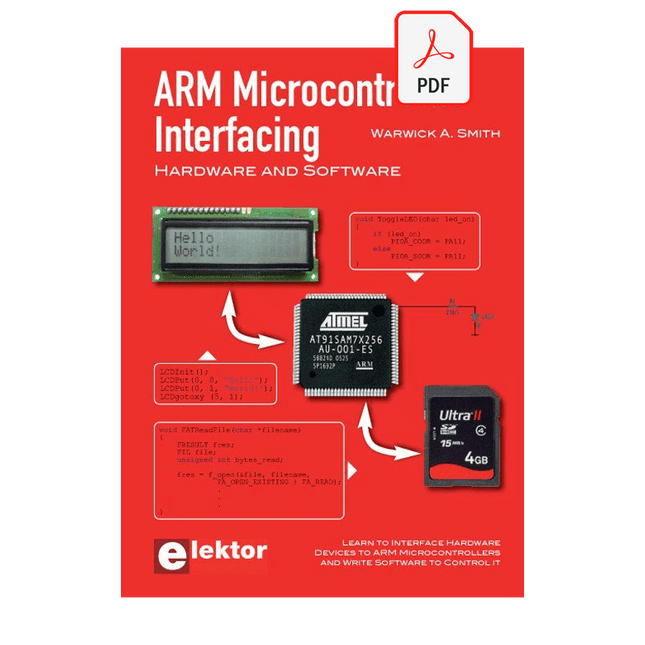
Learn to interface and program hardware devices in a wide range of useful applications, using ARM7 microcontrollers and the C programming language. Examples covered in full detail include a simple LED to a multi-megabyte SD card running the FAT file system.
Features of this book
Build prototype circuits on breadboard or Veroboard and interface to ARM microcontrollers.
A 32-bit ARM7 microcontroller is used in interfacing and software examples.
Interfacing principles apply to other ARM microcontrollers and other non-ARM microcontrollers as well.
Example programs are written in the C programming language.
Use only free or open source software.
Download and install all programming tools from the Internet.
Template project files are provided for easy project creation.
Hardware
Interface to LEDs, transistors, optocouplers, relays, solenoids, switches, keypads, LCD displays, seven segment displays, DC motors, stepper motors, external analogue signals using the ADC, RS232, RS-485, TWI, USB, SPI and SD memory cards.
Software
Once hardware has been interfaced to a microcontroller, software must be written to control the hardware. You will learn how to write programs to operate externally interfaced hardware devices, use timers and interrupts. Also learn how to port FAT file system code for use with an SD memory card, program the PWM to produce an audio sine wave, program the PWM to speed control a DC motor and more.
A chapter on more advanced ARM microcontrollers is included with an overview of some of the newest ARM microcontrollers and their features.
Elektor GREEN and GOLD members can download their digital edition here.
Not a member yet? Click here.
AI Tools for Hardware PrototypingWhat Helps, What Does Not, and Where the Engineer Still Has to Sit
ZSWatch — From Idea to ProductPart 1: A Completely Open Smartwatch
Three-Way Tone ControlHigh-End — For That Little Bit Extra
electronica Fast Forward 202610 Years of Innovation
Microcontroller PrototypingAn Overview of Popular Boards
Prototyping BreadboardsPeculiar Parts, the Series
Designing for OrbitA Maker’s Guide to COTS Selection, Radiation Resilience, and Mission Architecture
Thermal Management for Reliable ElectronicsWhen Every Degree Counts
From Concept to GadgetBuilding Embedded Systems That Ship
Understanding the EU Cyber Resilience ActWhat the CRA Demands and How to Meet It: A Guide for Embedded Engineers
Lusight: Printed Displays You Can Reveal with Your PhoneDiscover What Is Inside the Badge on the Cover of Elektor’s electronica Edition
Teaching a Robot Arm to See and MoveAI-Driven Manipulation Using a 3D-Printed Robot
Loop Antenna with RF BricksPart 2: Signal Processing
From Prototype to ProductionPractical Lessons from the Elektor Community
Project UpdatesFeedback, Ideas, Corrections
Handheld Audio GeneratorA Reference Signal Source for Quick Audio Systems Setup
AudiotronicsMore Distortion, and a Level-Matching Amplifier
2026: An AI OdysseyWhen AI Starts Building AI
Wireless Workshop (2)Radio Modules Unlocked: 2.4-GHz nRF24L01P Transceiver
The Digital Path
Building an Open-Source SmartwatchDaniel Kampert on ZSWatch, Open Hardware, and Engineering Trade-Offs
How to Prepare for Professional SMD Assembly
Engineering Beyond the BenchSystem Integration, Troubleshooting, and Real-World Testing
Elektor at 65Projects from Novembers and Decembers Past
Avionics Instrument SimulatorESP32-S3-Based, with Round HMI Display
DIE NEURONEN IN NEURONALEN NETZWERKEN VERSTEHENTeil 1. Künstliche Neuronen
EMV-VOR-KONFORMITÄTSTESTER FÜR IHR PROJEKT MIT DC-VERSORGUNGTeil 1: Was ist eine Netznachbildung?
ELEKTRONISCHE LAST FÜR DC UND ACBis zu 400 V und 10 A
ALLER ANFANG …ist gar nicht schwer!
NVIDIA JETSON NANO - BILDVERARBEITUNG FÜR EINSTEIGERTeil 1: Hard- und Software im Überblick
NETZTRANSFORMATOREN AUS DER NÄHE BETRACHTETWie verhalten sie sich beim Ein- und Ausschalten?
PICAN 3 - YES WE CAN!CAN-Zusatzboard für Raspberry Pi 4
BALKONKRAFTWERKSelbst installiert = schnell amortisiert!
FOTOGRAFIEREN UND VIDEO-STREAMING MIT DEM RASPBERRY PI 4Die High-Quality-Kamera des Raspberry Pi in der Praxis
VERWENDUNG VON DISPLAYS IN RASPBERRY-PI-PROJEKTENBeispiel-Kapitel: Organische Leuchtdioden-Displays (OLED)
PARALLAX PROPELLER 2Teil 4: Senden von Strings
60 JAHRE ELEKTOR: SEPTEMBER-RENAISSANCEDer Plan, der Plan, ein leerer Wahn ...
ZUTRITT FÜR UNBEFUGE VERBOTEN ERWÜNSCHTIn Friesland, wo die Röhren blühen ...
HYBRIDE SCHALTUNGENBemerkenswerte Bauteile
KOMPASSROSE MIT DEM GY-271Oder, warum man mit dem Handy Achten gehen muss…
KENNEN SIE IHREN FUSSABDRUCKBerechnen Sie die CO2-Bilanz Ihrer Elektronik
ESP32-VERBUNDENES THERMOSTATLagern Sie Ihren Wein bei der richtigen Temperatur!
MAGNETISCHE LEVITATION DIE DIGITALE ARTEin ESP32 Pico ersetzt den analogen Komparator
ULTIMATE ARDUINO UNO HARDWARE MANUALEin beispielhaftes Kapitel: Bootloader für den Haupt-Mikrocontroller
MICROPYTHON FÜR DEN ESP32 UND CO.Teil 2. Matrix-Displays einfach ansteuern
MADMACHINE SWIFTIO-KARTEModerne Sprache trifft moderne Hardware
AUS DEM LEBEN GEGRIFFENEine elektronische On/Off-Beziehung
HEXADOKUSudoku für Elektroniker
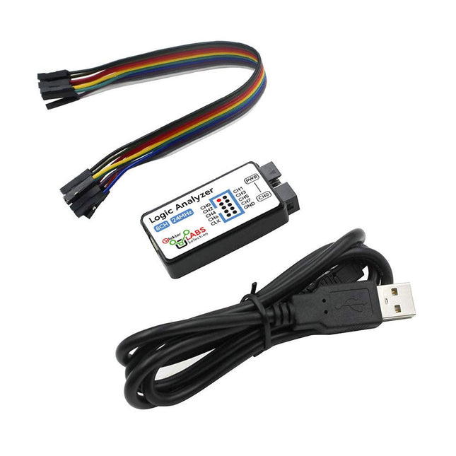
This USB Logic Analyzer is an 8-channel logic analyzer with each input dual purposed for analog data recording. It is perfect for debugging and analyzing signals like I²C, UART, SPI, CAN and 1-Wire. It operates by sampling a digital input connected to a device under test (DUT) at a high sample rate. The connection to the PC is via USB.
Specifications
Channels
8 digital channels
Maximum sampling rate
24 MHz
Maximum input voltage
0~5 V
Operating temperature
0~70°C
Input impedance
1 MΩ || 10 pF
Supported protocols
I²C, SPI, UART, CAN, 1-Wire, etc.
PC connection
USB
Dimensions
55 x 28 x 14 mm
Included
USB Logic Analyzer (8-ch, 24 MHz)
USB Cable
Jumper Wire Ribbon Cable
Downloads
Software
Der Einstieg in die Elektronik ist einfacher, als Sie denken! Mit diesem Bundle – bestehend aus Buch und Experimentierkit – entdecken Sie die Grundlagen der Elektro- und Elektroniktechnik Schritt für Schritt. Anhand spannender Experimente lernen Sie praxisnah und verständlich, ganz ohne komplizierte Fachbegriffe oder langwierige Berechnungen. So sind Sie schon bald in der Lage, Ihre eigenen Elektronikprojekte umzusetzen!
Das Kit enthält alle notwendigen Komponenten, um die meisten im Buch beschriebenen Schaltungen direkt auf dem Steckbrett aufzubauen und praktisch zu erproben.
Das Kit kann selbstverständlich auch ohne das Buch zum Aufbau anderer Schaltkreise und zur Durchführung eigener Experimente verwendet werden.
Inhalt des Kits
1x 39 Ω, 1 W Widerstand
1x 47 Ω Widerstand
1x 180 Ω Widerstand
1x 330 Ω Widerstand
3x 1 kΩ Widerstand
1x 2,2 kΩ Widerstand
1x 3,9 kΩ Widerstand
1x 6,8 kΩ Widerstand
1x 10 kΩ Widerstand
1x 15 kΩ Widerstand
1x 22 kΩ Widerstand
1x 33 kΩ Widerstand
1x 47 kΩ Widerstand
1x 56 kΩ Widerstand
1x 82 kΩ Widerstand
1x 120 kΩ Widerstand
1x 680 kΩ Widerstand
2x 100 kΩ Widerstand
1x 10 kΩ Trimmer
1x 10 kΩ Linearpotentiometer
1x 100 kΩ Linearpotentiometer
1x LDR
1x 1 nF Keramikkondensator
2x 10 nF Keramikkondensator
1x 100 nF Keramikkondensator
1x 1 µF, 25 V Aluminium-Elektrolytkondensator
2x 10 µF, 25 V Aluminium-Elektrolytkondensator
1x 100 µF, 25 V Aluminium-Elektrolytkondensator
1x 470 µF, 25 V Aluminium-Elektrolytkondensator
1x 1000 µF, 25 V Aluminium-Elektrolytkondensator
1x RGB-LED, Common-Cathode (CC)
1x 1N4148 Kleinsignaldiode
1x 1N4733A 5,1 V, 1 W Zenerdiode
3x LED, rot
2x BC337 NPN-Transistor
1x IRFZ44N N-Kanal-MOSFET
2x NE555-Timer
1x LM393-Komparator
1x 74HCT08 Quad-AND-Gatter
3x Tastschalter
2x SPDT-Schalter
1x Relais, SPDT, 9 VDC
1x Aktiver Summer
1x Passiver Summer
50 cm Massivdraht, 16 AWG, ohne Mantel
2x PP3 9 V Batterieclip
1x Steckbrett
20x Überbrückungskabel
Dieses Bundle enthält:
Buch: Schnelleinstieg in die Elektronik (Einzelpreis: 45 €)
Kit: Schnelleinstieg in die Elektronik (Wert: 45 €)
Zelfbouw versterkers en luidsprekers
Ook deze vijfde Audio Special staat weer vol met interessante bouwbeschrijvingen en achtergrondartikelen van internationaal gerenommeerde ontwerpers. Ook dit jaar weer de inmiddels bekende mix van buizenversterkers en luidsprekers, zodat er voor iedere zelfbouwer ongetwijfeld iets interessants te lezen of te bouwen valt. Het gaat in alle gevallen om nieuwe, nog niet eerder gepubliceerde artikelen.
Inhoud
Versterkers
Classic Three voorversterker
Lijnvoorversterker met 6C33
De Dirigent – buizenvoorversterker met actief scheidingsfilter
Single ended KR300B stereo eindversterker
1 Watt gitaarversterker – voor huiskamer
Single ended 211 triode versterker – met interstage trafo
Dieper kijken in de uitgangstransformator
Prelude voorversterker – minimalisme in optima forma
Klik aan, klik uit schakelaar – een netschakelaar met legio toepassingen
Luidsprekers
Scheidingsfilters voor luidsprekerboxen – meer valkuilen dan je lief is
Morel Elite 420 – actieve tweeweg boekenplank luidspreker
All back – een verrassend veelzijdige compacte TL
HATT-SE MkII Micro Monitor – kleine luidspreker met pit
Silverado – een d’Appolito met pit
Nebular Monitor – een compacte luidspreker met een groots geluid
LBVS – zelfbouwklassieker van eigen bodem
Solo 201 – er is maar één weg!
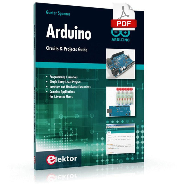
Two reasons can be identified for the immense success of the Arduino platform. First, the cheap, ready to go processor board greatly simplifies the introduction to hardware. The second success factor is the free and open-source programming suite that does not require an installation procedure.
Simple entry-level examples ensure rapid successes. Complex selection procedures for parameters like the microprocessor version or interface settings are not required. The first sample programs can be uploaded to the Arduino board, and tested, in a matter of minutes.
The Arduino user is supported by an array of software libraries. However, the daily increasing volume of libraries poses initial problems to the newcomer, and the way ahead may be uncertain after a few entry-level examples. In many cases, detailed descriptions are missing, and poorly described projects tend to confuse rather than elucidate. Clear guidance and a single motto are missing, usually owing to the projects having been created by several different persons—all with different aims in mind.
This book represents a different approach. All projects are presented in a systematical manner, guiding into various theme areas. In the coverage of must-know theory great attention is given to practical directions users can absorb, including essential programming techniques like A/D conversion, timers and interrupts—all contained in the hands-on projects. In this way readers of the book create running lights, a wakeup light, fully functional voltmeters, precision digital thermometers, clocks of many varieties, reaction speed meters, or mouse controlled robotic arms. While actively working on these projects the reader gets to truly comprehend and master the basics of the underlying controller technology.