
Search results for "elektor or magazine or fr or septembre or 2016"
-
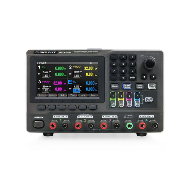
Siglent Siglent SPD4306X 4-ch DC Power Supply (400 W)
The Siglent SPD4306X is a 4-channel DC Linear Programmable Power Supply equipped with a 4.3-inch TFT-LCD display, friendly human-machine interface, and excellent performance indicators. Real-time waveform display provides engineers with an informative user interface. SPD4306X offers a total output power of 400 W with a resolution of 1 mV/1 mA. The maximum voltage and current for each channel are as follows: CH1: 15 V/1.5 A CH2: 30 V/6 A CH3: 30 V/6 A CH4: 15 V/1 A Features Rated output power: 400 W Rated voltage: 32 V, 12 V, 30 V Up to four high-precision power supplies with independent controllable outputs, supporting CH2 and CH3 series and parallel connections Clear graphical interface with waveform and timer display modes 5-digit voltage and current display with minimum resolution of 1 mV, 1 mA Fast output response time: <50us The high current channel support remote voltage compensation sense function. The maximum compensation voltage is 0.6 V Overvoltage protection and overcurrent protection or safe and accurate operation Equipped with a 4.3-inch TFT-LCD display (480 x 272 resolution) USB and LAN standard communication USB-GPIB module is optional Excellent channel density with up to 4 channels in a 3U half rack package Internal data storage for setups and parameters Embedded Web Server with instrument communication that doesn’t require software installation Fully SCPI programming command set support as well as a LabView driver for remote control and system automation Specifications SPD4323X SPD4121X SPD4306X Channel Output CH1: Voltage 0 to 6 V Current 0 to 3.2 ACH2: Voltage 0 to 32 V Current 0 to 3.2 ACH3: Voltage 0 to 32 V Current 0 to 3.2 ACH4: Voltage 0 to 6 V Current 0 to 3.2 A CH1: Voltage 0 to 15 V Current 0 to 1.5 ACH2: Voltage 0 to 12 V Current 0 to 10 ACH3: Voltage 0 to 12 V Current 0 to 10 ACH4: Voltage 0 to 15 V Current 0 to 1.5 A CH1: Voltage 0 to 15 V Current 0 to 1.5 ACH2: Voltage 0 to 30 V Current 0 to 6 ACH3: Voltage 0 to 30 V Current 0 to 6 ACH4: Voltage 0 to 15 V Current 0 to 1 A Resolution 1 mV, 1 mA 1 mV, 1 mA 1 mV, 1 mA Setting Accuracy Voltage: ±(0.03% of reading+10) mV, Current: ±(0.3% of reading+10) mA Voltage: ±(0.03% of reading+10) mV, Current: ±(0.3% of reading+10) mA Voltage: ±(0.03% of reading+10) mV, Current: ±(0.3% of reading+10) mA Readback Accuracy Voltage: ±(0.03% of reading+10) mV, Current: ±(0.3% of reading+10) mA Voltage: ±(0.03% of reading+10) mV, Current: ±(0.3% of reading+10) mA Voltage: ±(0.03% of reading+10) mV, Current: ±(0.3% of reading+10) mA Display 4.3" TFT-LCD 5-digit voltage and current display 4.3" TFT-LCD 5-digit voltage and current display 4.3" TFT-LCD 5-digit voltage and current display Output power 240 W 285 W 400 W Included 1x Siglent SPD4306X Power Supply 1x Power cord (EU) 1x Output test cord (3 A) 1x USB cable 1x Quick start guide Downloads Datasheet Manual Quick start
€ 1.101,10
-
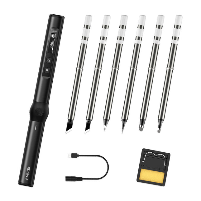
FNIRSI FNIRSI HS-01 Smart Soldering Iron (incl. 6 Soldering Tips)
The perfect tool for quick repairs The FNIRSI HS-01 is a powerful, adjustable smart soldering iron with a built-in 0.87-inch OLED display that quickly reaches temperatures between 80-420°C (180-780°F). The display shows all important information, including the status of the temperature level, the set temperature, the supply voltage and the power percentage. You can set the input voltage from 9-20 V directly in the menu according to your needs. The integrated sleep mode automatically turns off the iron after 30 minutes. Features 96 W input (DC) 65 W PD power OLED display Constant temperature & fast heating CNC metal integral molding Smart safety anti-scald Mini pocket size Ergonomic design Aluminum material Left/right hand switch Efficient heat radiation Inductive sleep Color: Black Specifications Power 65 W Screen 0.87" OLED Operating voltage 9-20 VDC Power supply USB-C Temperature range 80-420°C (180-780°F) Fast charging protocol PD trigger Dimensions 184 x 20 x 20 mm (7.24 x 0.79 x 0.79') Weight 56 g Power Selection Operating voltage 20 V 15 V 12 V 9 V Operating current ≥3.25 A ≥2.5 A ≥2 A ≥1.5 A Power 65 W 37.5 W 24 W 13.5 W Tin melting time 8s 12s 17s 30s Included 1x FNRISI HS-01 smart soldering iron 6x Soldering iron tips (HS01-BC2, HS01-KR, HS01-K65, HS01-B2, HS01-ILS, HS01-BC3) 1x DC to USB-C power cable 1x Mini soldering iron stand 1x Manual Required Power adapter USB-C cable Downloads Manual Firmware V0.3.s19
€ 82,00
-
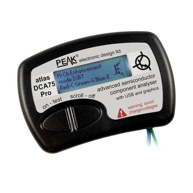
Peak Peak Atlas DCA75 Pro (Advanced Semiconductor Analyzer)
The DCA75 Pro is a great instrument that combines ease-of-use with amazing features. It can automatically identify a huge range of semiconductors, automatically identify pinouts and measure detailed parameters. Features Built-in graphics display (now backlit) to show detailed schematic of the component you're testing as well as pinout and measurement data USB connectivity to allow curve tracing, data storage/retrieval and device matching on your Windows PC (Windows 7 and higher) Single internal AAA alkaline cell for standalone operation Component Support Bipolar transistors (NPN/PNP inc Silicon/Germanium) Darlington transistors (NPN/PNP) Enhancement mode MOSFETs (N-Ch and P-Ch) Depletion mode MOSFETs (N-Ch and P-Ch) Junction FETs (N-Ch and P-Ch). Both symmetrical and asymmetrical types Enhancement IGBTs (N-Ch and P-Ch) Diodes and diode networks (2 and 3 lead types) Zener diodes (up to about 9 V) Voltage regulators (up to about 8 V) LEDs and bi-colour LEDs (2 lead and 3 lead types) Low power sensitive Triacs and Thyristors (<10 mA trigger and hold) Measurements BJT current gain (hFE) BJT base emitter voltage (Vbe) BJT collector leakage current MOSFET on and off gate threshold voltages MOSFET transconductance JFET pinch-off voltage JFET transconductance JFET IDSS (drain current for Vgs=0) IGBT on and off gate threshold voltages IGBT transconductance Voltage regulator output voltage Voltage regulator quiescent current consumption Voltage regulator drop-out voltage Zener voltage Diode forward voltage drop Specifications Analyzer type Semiconductor components Component detection Automatic Pinout detection Automatic, connect any way round Display type Graphic LCD (now backlit) Interface type USB for optional PC connection PC functions Curve tracing (Windows 7 and higher) Software Included on USB drive for Windows 7 and higher Battery Single AAA cell (supplied) Included Peak Atlas DCA75 Pro PC software on a USB Flash Drive for Windows 11, 10, 8, 7, XP Micro USB cable Fitted universal premium hook probes AAA Alkaline battery Downloads Datasheet (EN) User Guide (EN) User Guide (IT) Software Installation Guide (EN) Software and Firmware Package
€ 192,39
-

OWON OWON XDM1241 True RMS Multimeter
The OWON XDM1241 is a fast, high-precision digital True RMS benchtop multimeter with a high-resolution 3.5-inch LCD and 50,000 counts. Its DC voltage accuracy is up to 0.05% and it can measure up to 65 values per second. Features 3.5' high-resolution LCD (480x320 pixels) 55000 counts, DC voltage accuracy up to 0.05% Up to 65 readings per second Dual line display supported Trend analysis accessible in chart mode AC True RMS measurements (bandwidth: 20 Hz – 1 kHz) SCPI support: Remote control the multimeter through PC software via USB port Data record function, you can record the measured data into internal memory, and then read and process the recorded data with your computer. Specifications Measurement Range Resolution Accuracy DC Voltage 50.000 mV 0.001 mV 0.1% +10 500.00 mV 0.01 mV 0.05% +5 5.0000 V 0.0001 V 0.05% +5 50.000 V 0.001 V 0.05% +5 500.00 V 0.01 V 0.1% +5 1000.0 V 0.1 V 0.1% +10 AC Voltage 500 mV~750 V 20 Hz~45 Hz 1% +30 45 Hz~65 Hz 0.5% +30 65 Hz~1 KHz 0.7% +30 DC Current 500 uA 0.01 uA 0.15% +20 5000 uA 0.1 uA 0.15% +10 50 mA 0.001 mA 0.15% +20 500 mA 0.01 mA 0.15% +10 5 A 0.0001 A 0.5% +10 10 A 0.001 A 0.5% +10 AC Current 500 uA~500 mA 20 Hz~1 KHz 0.5% +20 5 A-10 A 1.5% +20 Resistance 500 Ω 0.01 Ω 0.15% +10 5 KΩ 0.0001 KΩ 0.15% +5 50 KΩ 0.001 KΩ 0.15% +5 500 KΩ 0.01 KΩ 0.15% +5 5 MΩ 0.0001 MΩ 0.3% +5 50 MΩ 0.001 MΩ 1% +10 Frequency 10.000 Hz~60 MHz / ±(0.2% +10) Capacitance 50 nF~500 uF / 2.5% +10 5 mF~50 mF 5% +10 Diode 3.0000 V 0.0001 V / Continuity 1000 Ω 0.1 Ω Adjustable threshold Temperature K type, PT100 Max Display 55,000 counts Data-logging Function Logging Duration 15ms~9999.999s Logging Length 1,000 points Display 3.5' TFT LCD (480x320 pixels) Power supply Lithium battery via USB-C or 5 V DC input Dimensions 235 x 88 x 65 mm Weight approx. 0.5 kg Included 1x OWON XDM1241 Multimeter 2x Test leads 1x USB cable 1x USB to DC cord 1x Manual Downloads Programming Manual PC Software
€ 108,90
-

Würth Trilogie der Steckverbinder, 3. Auflage (E-book)
Inhalt Grundlagen Ein Steckverbinder ist ein elektromechanisches System, das eine lösbare Verbindung zwischen zwei Subsystemen eines elektronischen Gerätes ohne inakzeptable Auswirkung auf die Funktion des Gerätes schafft. Im Folgenden wird dargestellt, dass es eine Menge komplexer Zusammenhänge gibt, die richtig gehandhabt werden müssen, um diese Aussage wahr werden zu lassen. Kontaktdesign & Verbindungstechnik Dieses Kapitel bietet einen Überblick über die Ausführungen und die Materialanforderungen bei Kontaktbeschichtungen, Kontaktfedern und Steckverbindergehäusen und beschreibt zudem die wichtigsten Schädigungen bei diesen Steckerkomponenten. Ferner werden wir uns hier den Kriterien für die Materialauswahl widmen. Neu hinzugekommen ist das Konzept des „Level of Interconnection“ (LOI). Hier wird beschrieben, an welcher Stelle der Steckverbinder innerhalb eines elektronischen Systems eingesetzt wird und seinerseits abhängig von der Verwendung die Anforderungen und die eigene Lebensdauer beeinflusst. Anwendungen Dieses Kapitel zielt auf die Praxis ab: Hier wird gezeigt, wie Kunden Steckverbinder in ihren Anwendungen einsetzen. So werden einige Möglichkeiten veranschaulicht, um Ihre tägliche Arbeit zu erleichtern. Auch enthält das Kapitel einige Spezialthemen, die Ihnen erweitertes Hintergrundwissen vermitteln sollen. Hierzu gehören etwa die Whiskerbildung im Zinn oder die Impedanz von ZIF-Kabeln.
€ 26,99
Members: € 24,29
-
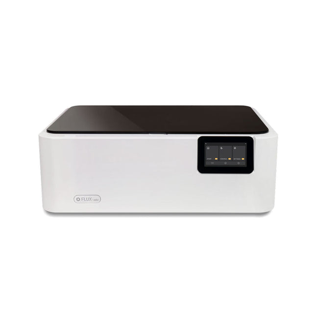
FLUX FLUX Ador Laser Cutter (20 W)
FLUX Ador is the world's first color printing laser cutter. Powered by three high-quality, interchangeable modules, Ador enables you to engrave and cut though a wide range of materials while enhancing your projects with a pop of color. New creative potential with Ador Whether you’re an educator, small business, crafter or designer, with Ador, the application boundary is for you to define. Easy to use Place material then autofocus Drag and drop your design Engrave, cut or print Project Completed! Big workspace, big ideas Ador offers a big working space of 430 x 300 mm, with a depth of 30 mm, expanding the horizons of your creativity. Specifications Dimensions 637 x 488 x 226 mm Weight 19 kg Work Area X&Y: 20 W Diode laser: 430 x 300 mm (X & Y varies with different modules)Z: 30 mm (for all modules) & 20 mm (with prism) Camera Preview Area Whole work area Voltage AC 110-240 V Touch Panel Yes, 8 inches (diagonal) Camera 8 MP I/O USB / WiFi Laser Spec W Diode laser Module Laser Moving Speed 0~400 mm/s Laser Cutting Thickness Varies for different materials Software Mode Vector / Graphic (monochrome, gray scale) Operating System Windows / macOS / Linux Software File Type JPG / PNG / SVG / DXF Included FLUX Ador 20 W diode laser module 6x prism lift Power adapter Power cord Hex key Vent Hose Vent hose Duct Clamp Wooden test piece Laser Cutter Lubricant Downloads Firmware
€ 1.935,00
Best Price
-

Elektor Digital Visual Basic für Elektroniksteuerungen und Entwicklung (E-book)
Der PC wird schon lange nicht mehr nur als einfacher Computer verwendet, sondern hat sich zu einem Universalwerkzeug entwickelt. Dieses Buch richtet sich an diejenigen, die vorhandene oder selbstgebaute Hardware über den Computer steuern wollen. Der Einsatz von Visual Basic für die schnelle Entwicklung von Elektronikapplikationen öffnet Ihnen eine Welt, die über die Anschlüsse des PCs hinausreicht. Sobald Sie sich mit Visual Basic, seiner Entwicklungsumgebung und den angebotenen Toolsets vertraut gemacht haben, werden Dinge wie die serielle Kommunikation, Druckerports, Bitbanging, Protokoll-Emulation, die ISA-, USB- und Ethernet-Schnittstellen und die Fernsteuerung von Mess- und Testaufbauten über den GPIB-Bus in allen Einzelheiten behandelt. Zu jedem Punkt gibt es einen übersichtlichen und lauffähigen Programmcode und wo nötig existieren Schaltpläne, mit denen Sie Ihr Projekt in kurzer Zeit einsatzfähig machen können. Darüber hinausgehend erläutert dieses Buch den Umgang mit Debug-Tools bei der Suche nach Hardware-Adressen, den Aufbau einer Verbindung über TCP/IP- und UDP-Sockets und Sie lernen sogar eigene Internetserver zu programmieren. Oder wollen Sie Ihre Hardware über USB oder Ethernet anbinden und mit Visual Basic steuern? Auch die Kommunikation zwischen Programmen, DDE und das neue Grafik-Interface von Windows XP werden behandelt. Alle Programmbeispiele lassen sich mit Visual Basic 5.0, 6.0, .NET oder 2005 kompilieren. Auch die Unterschiede zwischen Visual Basic Classic und Visual Basic NET/2005 sind ausführlich erläutert.
€ 39,80
Members: € 35,82
-

Elektor Digital Motorsteuerung mit Arduino und Raspberry Pi (PDF)
Dieses Buch beschäftigt sich mit DC-Elektromotoren und deren Einsatz in Arduino und Raspberry Pi Zero W-Projekten. Das Buch enthält zahlreiche Motorsteuerungsprojekte, wobei jedes Projekt denselben Aufbau besitzt: Projekttitel Beschreibung des Projekts Blockschaltbild Schaltplan Zusammenbau Vollständiges Programmlisting Umfassende Erläuterung des Programms Die Projekte im Buch umfassen die Standard-DC-Motoren, Schrittmotoren, Servomotoren und mobile Roboter. Das Buch richtet sich an Elektronik-Bastler, die Projekte mit dem Arduino Uno oder dem Raspberry Pi Zero W entwickeln und dabei Motoren einsetzen möchten. Ein besonders reizvolles Projekt dieses Buches ist die Fernsteuerung eines mobilen Roboters von einem Mobiltelefon aus mit dem Arduino Uno sowie dem Raspberry Pi Zero W. Dieses Projekt wird sowohl über Wi-Fi als auch über Bluetooth mit dem Handy gesteuert. Die Leser sollten in der Lage sein, einen Roboter vorwärts, rückwärts, links oder rechts zu bewegen, indem sie einfache Befehle vom Mobiltelefon aus senden. Die vollständigen Programmlistings aller Projekte sowie die detaillierten Programmbeschreibungen finden Sie im Buch. Der Leser kann die Projekte Schritt für Schritt nachbauen oder sie an die eigenen Bedürfnisse anpassen.
€ 32,80
Members: € 29,52
-
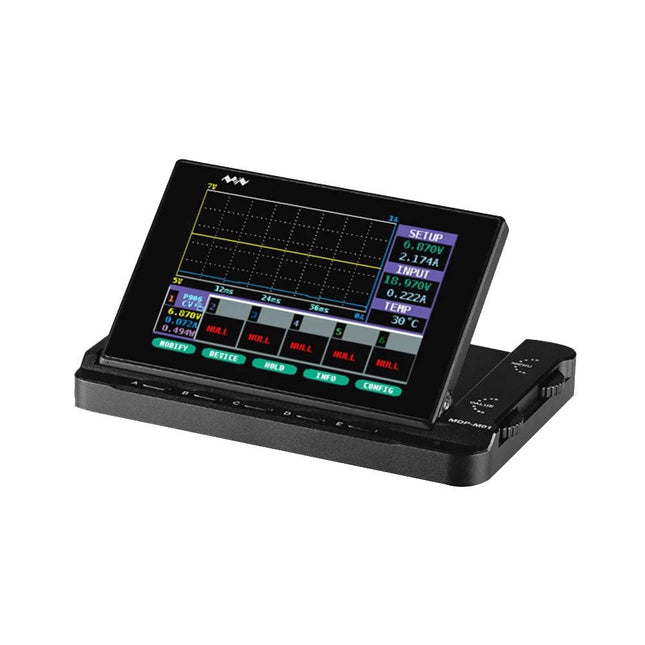
Miniware Miniware MDP-M01 Smart Digital Monitor
MDP-M01 is a display control module equipped with a 2.8-inch TFT display screen, the screen can be turned 90 degrees, which is convenient for users to view data and waveform. MDP-M01 can realize online display and control with MDP-P906 mini digital power supply modules and other modules of MDP system through 2.4 GHz wireless communication, and can control up to 6 sub-modules at the same time. Specifications Screen size 2.8" TFT Screen resolution 240 x 320 Power Micro USB power input, or taking power from sub-module via dedicated power cable Input DC 5 V/0.3 A Other functions Can control up to 6 sub-modulesUpgrade firmware through Micro USB Dimensions 107 x 66 x 13.6 mm Weight 133 g Included 1x MDP-M01 Smart Digital Monitor 1x Cable (2.5 mm jack to Micro USB) Downloads User Manual v3.4 Firmware v1.32
€ 79,00
-

Würth Abc of Power Modules (E-book)
Functionality, structure and handling of a power module For readers with first steps in power management the “Abc of Power Modules” contains the basic principles necessary for the selection and use of a power module. The book describes the technical relationships and parameters related to power modules and the basis for calculation and measurement techniques. Contents Basics This chapter describes the need of a DC/DC voltage converter and its basic functionality. Furthermore, various possibilities for realizing a voltage regulator are presented and the essential advantages of a power module are mentioned. Circuit topologies Circuit concepts, buck and boost topologies very frequently used with power modules are explained in detail and further circuit topologies are introduced. Technology, construction and regulation technology The mechanical construction of a power module is presented, which has a significant influence on EMC and thermal performance. Furthermore, control methods are explained and circuit design tips are provided in this chapter. Measuring methods Meaningful measurement results are absolutely necessary to assess a power module. The relevant measurement points and measurement methods are described in this chapter. Handling The aspects of storage and handling of power modules are explained, as well as their manufacturing and soldering processes. Selection of a power modules Important parameters and criteria for the optimal selection of a power module are presented in this section.
€ 8,99
Members: € 8,09
-

Arduino Official Arduino USB-C Cable (2-in-1)
Now you can connect your Arduino boards with the official Arduino USB cable. Through a USB-C to USB-C with a USB-A adapter connection, this data USB cable can easily connect your Arduino boards with your chosen programming device. The Arduino USB cable has a nylon braided jacket in the typical Arduino colors white and teal. The connectors have an aluminum shell that protects your cable from harm at the same time as looking cool. Length: 100 cm Aluminium shell with logo Nylon braided jacket white and teal
€ 12,95
Members: € 11,66
-

Elektor Digital LabVIEW 2 (PDF)
Das Programmpaket Laboratory Virtual Instrument Engineering Workbench (oder kurz LabVIEW) ist ein international anerkannter Standard zur Entwicklung und Gestaltung von Messgeräten und Prozesssteueroberflächen. Seine Universalität konfrontiert den LabVIEW-Einsteiger allerdings mit einer unübersichtlichen Vielfalt von Funktionen, die er ohne fundierte Anleitung kaum überblicken kann. Hier setzt diese neue mehrteilige Lehrbuchreihe an: Von Grund auf werden in einfach nachvollziehbaren Schritten der Aufbau, die Struktur und die Verwendung von LabVIEW erklärt, in praktischen Beispielen dargestellt und mit Übungen vertieft. Die notwendigen Vorkenntnisse sind äußerst gering, die erreichbaren Ergebnisse dagegen äußerst sehenswert. Der erste Band erläutert die Grunddatentypen und die zugehörigen numerischen Grundfunktionen ebenso ausführlich wie die elementaren Programmstrukturen. Im folgenden Band liegt der Schwerpunkt bei der Kopplung beliebiger Mikrocontrollersysteme über die serielle (USB-)Schnittstelle an den PC und an LabVIEW. Im dritten Band stehen Entwurf und Betrieb kompletter MSR-Systeme mit Hard- und Softwarekomponenten der wichtigsten Messtechnikhersteller im Vordergrund, einschließlich Fernsteuerung, -überwachung und -diagnose über das Internet oder WLAN-Systeme. Diese Lehrbuchreihe richtet sich an Schüler/Auszubildende technischer Bildungseinrichtungen, an Studenten von Fachhochschulen/Universitäten und an den engagierten Praktiker in der Industrie oder im privaten Bereich.
€ 32,80
Members: € 29,52


