Raspberry Pi 5 provides two four-lane MIPI connectors, each of which can support either a camera or a display. These connectors use the same 22-way, 0.5 mm-pitch “mini” FPC format as the Compute Module Development Kit, and require adapter cables to connect to the 15-way, 1 mm-pitch “standard” format connectors on current Raspbery Pi camera and display products.These mini-to-standard adapter cables for cameras and displays (note that a camera cable should not be used with a display, and vice versa) are available in 200 mm, 300 mm and 500 mm lengths.
With this 65 W USB-C PD power supply (with GaN technology) you can start using the FNIRSI HS-01 soldering iron straight away. Of course, you can also use this charger to fast charge your tablets and smartphones via USB-C and USB-A.
Included
65 W USB-C PD GaN Power Supply (EU)
The Siglent SDM3045X is a 4½ digit digital (66000 counts, sampling rate 150 Sa/s) multimeter incorporating a dual-display and is especially well suited for the needs of high-precision, multifunction and automatic measurement.
With its large 4.3" (10.9 cm) TFT color display (480x272 pixels), the menu navigation is very intuitive to use and very easy to read.
Features
Real 4½ digit (66000 counts) readings resolution
Up to 150 rdgs/s measurement speed
True-RMS AC Voltage and AC Current measuring
1 GB NAND flash size, mass storage configuration files and data files
Built-in cold terminal compensation for thermocouple
With easy, convenient and flexible PC software: EasyDMM
Standard interface: USB Device, USB Host, LAN
USB & LAN remote interfaces support common SCPI command set. Compatible with other popular DMMs on the market.
Application Fields
Research Laboratory
Development Laboratory
Detection and Maintenance
Calibration Laboratory
Automatic Production Test
Measurement Functions
DC Voltage: 600 mV – 1000 V
DC Current: 600 μA – 10 A
AC Voltage: True-RMS, 600 mV – 750 V
AC Current: True-RMS, 60 mA – 10 A
2/4-Wire Resistance: 600 Ω – 100 MΩ
Capacitance: 2 nF – 10000 μF
Continuity Test: Range is fixed at 2 kΩ
Diode Test: Adjustable range is 0-4 V
Frequency Measurement: 20 Hz – 500 KHz
Period Measurement: 2 μs – 0.05 s
Temperature: Support for TC and RTD sensor
Max, Min, Average, Standard Deviation, dBm/dB, Relative Measurement, Pass/Fail, Histogram, Trend Chart
Specifications
DC voltage
200 mV, 2 V, 20 V, 200 V, 1000 V
DC current
200 μA, 2 mA, 20 mA, 200 mA, 2 A, 10 A
AC voltage
True-RMS, 200 mV, 2 V, 20 V, 200 V, 750 V
AC current
True-RMS, 20 mA, 200 mA, 2 A, 10 A
2/4-wire resistance
200 Ω, 2 K, 20 K, 200 K, 2 M, 10 M, 100 MΩ
Capacitance
2 nF, 20 nF, 200 nF, 2 μF, 20 μF, 200 μF, 10000 μF
Connectivity Test
Range fixed 2 KΩ
Diode test
Range fixed 2 V
Frequency
20 Hz ~ 1 MHz
Period
1 μs ~ 0.05 s
Temperature
Support thermocouple, RTD temperature sensor
Maximum input voltage
1000 V
Configuration Interface
USB Device, USB Host, LAN
Included
1x Siglent SDM3065X Multimeter
2x Multimeter Probes
1x Power Cord
1x USB Cable
1x Quick Start Guide
Downloads
User Manual
Datasheet
Remote Manual
Service Manual
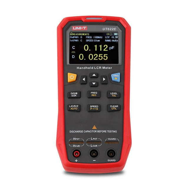
The UT622E handheld LCR meter features powerful functions, high accuracy, fast speed, and long standby time. With a clear and intuitive 2.8-inch TFT LCD display, large-capacity rechargeable battery, and 100 kHz test frequency, the meter can be used for longstanding accurate and convenient measurement in any occasion.
It is suitable for the measurement and screening of inductance, capacitance, and resistance in laboratories, production lines, maintenance points, etc.
Features
Max. test frequency: 100 kHz
Accuracy: 0.1%
Display count: 99999
Max. test rate: 20 times/s
DCR: Yes
Connectivity: Mini-USB
Display: 2.8" TFT LCD
Specifications
Testfrequency
100 Hz, 120 Hz, 1 kHz, 10 kHz, 100 kHz
Test level
0.1 Vmrs, 0.3 Vrms, 1 Vrms
Output impedance
100 Ω
Measurement parameters
Primary: L/C/R/Z/DCRSecondary: D/Q/Θ/ESR
DSR speed test
Fast (20 times/s), medium (5 times/s), or slow (2 times/s)
Range
Auto/Hold
Tolerance range
1%~20%
Equivalent mode
Series/Parallel
Clearing connection
Open/Short circuit
Fuse of test ports
0.1 A/250 V
Communication interface
Mini-USB
MAX reading of primary parameters
99999
MIN resolution
0.0001
Maximum accuracy
0.10%
L
0.00 µH~99.999 H
C
0.00 pF~99.999 mF
Z/R
0.0000 Ω~9.9999 MΩ
ESR
0.0000 Ω~999.99 Ω
D
0.0000~9.9999
Q
0.0000~99999
Θ
-179.9°~179.9°
DCR
0.01 mΩ~20.000 MΩ
Power supply
3.7 V/1800 mAh lithium polymer battery
Display
2.8" TFT LCD (320x240)
Dimensions
93 x 192 x 44 mm
Weight
420 g
Included
UT622E LCR meter
Short circuit board
Four-terminal kelvin test leads
USB cable
Manual
Downloads
Datasheet
Manual
Software
Specifications
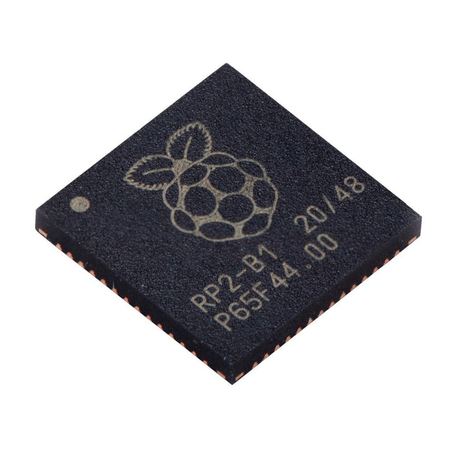
Dual ARM Cortex-M0+ @ 133 MHz
264 kB on-chip SRAM in six independent banks
Support for up to 16 MB of off-chip Flash memory via dedicated QSPI bus
DMA controller
Fully-connected AHB crossbar
Interpolator and integer divider peripherals
On-chip programmable LDO to generate core voltage
2x on-chip PLLs to generate USB and core clocks
30x GPIO pins, 4 of which can be used as analogue inputs
Peripherals
2x UARTs
2x SPI controllers
2x I²C controllers
16x PWM channels
USB 1.1 controller and PHY, with host and device support
8x PIO state machines
What you'll get
10x bare RP2040 chips
The OWON SDS1102 is an affordable benchtop digital oscilloscope that combines solid performance with essential measurement features. This 2-channel oscilloscope offers a 100 MHz bandwidth, a 1 GS/s sampling rate, a 7-inch LCD display, and a 10 kpts memory depth, making it a practical choice for everyday electronics testing, troubleshooting, and education.
The SDS1102 features a simplified trigger system with level and edge triggering, making it easy to capture and analyze common signals. It is designed for applications that do not require deep memory or advanced trigger functions, offering a straightforward and cost-effective solution for basic signal analysis.
Features
Bandwidth: 100 MHz
2 channels
Sample rate: 1 GS/s
Ultra-thin body
7-inch high-res LCD
SCPI and LabVIEW supported
Specifications
Bandwidth
100 MHz
Horizontal Scale (s/div)
5 ns/div – 1000 s/div
Channel
2
Vertical Sensitivity
5 mV/div – 5 V/div (at input)
DC Gain Accuracy
3%
Vertical Resolution (A/D)
8 bits (2 channels simultaneously)
Input
Input Impedance
1 MΩ, 10 pF
Input Coupling
AC, DC, GND
Max Input Voltage
±400 V, CATI, CATII
Passive probes
х1; х10
Probe Attenuation Factor
х1; х10; х100; х1000
Trigger System
Trigger Mode
Auto, Normal, Single
Trigger Type
Edge, Video
Edge Trigger Source
CH1, CH2
Video Trigger
Sampling Type
Real-time
Sample Rate
1 GS/s
Equivalent Sample Rate
No
Wavelength
10K pts
Interpolation
sin(x)/x
Measurement and Mathematical Treatment System
Automatic Measurement
Vpp, Vavg, RMS, Frequency, Period, Vmax, Vmin, Vtop, Vbase, Width, Overshoot, Pre-shootRise time, Fall time, +Width, -Width, +Duty, -Duty, Delay A→B, Delay A→B, area, cycle area
Math Functions
Addition, Subtraction, Multiplication, Division, FFT
General Characteristics
Display type
7" color LCD
Display Resolution
800 x 480
Power
100-240 V, 45-440 Hz, <15 W
Dimensions
301 x 70 x 152 mm
Weight
1.1 kg
Included
1x OWON SDS1102 Oscilloscope
2x Oscilloscope probes
1x Probe adjust
1x Mains power cord
1x USB cable
1x CD-Rom
1x Quick guide
Downloads
Quick Guide
Manual
PC Software
SCPI Commands
MDP-P906 has a built-in cooling fan, and maximum output power of up to 300 W, which meets a wider range of testing needs and application scenarios. Through 2.4 GHz wireless communication, it can be connected to MDP-M01 Smart Digital Monitor module to realize the free combination of multiple channels of 300 W per channel.
MDP-P906 has the index, stability and reliability comparable to a professional power supply. It can output pure current, and provide powerful functions such as programmable output, timing output, timing control, automatic compensation, boost mode, etc., making itself a real cost-effective, smart and customized programmable linear DC power supply.
MDP-P906 adopts a precision CNC machined aluminum alloy shell, with fine workmanship, novel, mini and beautiful appearance, it completely subverts the rigid image of traditional desktop power supply. With stackable modular design and wireless communication function, MDP-P906 can work independently or paired, both on the workbench, and be carried out for on-site maintenance. MDP-P906 is a perfect solution for electronic engineer, especially field application engineers to meet different needs of power sources.
Built-in silent cooling fan, instant cooling, ensure a stable and efficient output!
Smart linear compensation, constant voltage & constant current
Positive & negative output, series boost, parallel current sharing
Applications
Universal tests and teaching experiments in R&D laboratory
Maintenance of digital products
Property verification and fault diagnosis of devices and circuits
Emergency power supply for model airplanes and vehicles
Power supply testing of RF and microwave circuits or modules
Quality control and quality inspection
Supply purified power for high-accuracy digital-analog hybrid circuits and Hi-Fi audio devices
Specifications
Input
DC 4.2-30 V/14 A (Max)QC 3.0/PD2.0, 20 V/5 A (Max)
Output
0-30 V/0-10 A, 300 W (Max)
Conversion efficiency
95%
Output resolution
10 mV/2 mA, up to 1 mV/1 mA via Display Control module
Output accuracy
0.03%+5 mV0.05%+2 mV
Adjustment rate
Load adjustment rate <±0.01%Power adjustment rate <±0.01%
Ripple and noise
<250 uVrms, 3 mVpp; 2 mArms
Transient response
<4 uS
Safety protections
Input over-voltage, under-voltage, reverse connection protection, output over-current, back-flow protection and over-temperature protection
Others
Automatically shut-down and enter micro-power modeSupport USB firmware upgrade
Dimensions
112 x 66 x 20 mm
Weight
181 g
Included
1x MDP-P906 Digital Power Supply
2x Output Cable
1x User Manual
Downloads
User Manual v1.1
Firmware v1.32
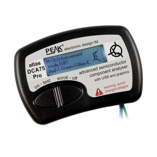
The DCA75 Pro is a great instrument that combines ease-of-use with amazing features. It can automatically identify a huge range of semiconductors, automatically identify pinouts and measure detailed parameters.
Features
Built-in graphics display (now backlit) to show detailed schematic of the component you're testing as well as pinout and measurement data
USB connectivity to allow curve tracing, data storage/retrieval and device matching on your Windows PC (Windows 7 and higher)
Single internal AAA alkaline cell for standalone operation
Component Support
Bipolar transistors (NPN/PNP inc Silicon/Germanium)
Darlington transistors (NPN/PNP)
Enhancement mode MOSFETs (N-Ch and P-Ch)
Depletion mode MOSFETs (N-Ch and P-Ch)
Junction FETs (N-Ch and P-Ch). Both symmetrical and asymmetrical types
Enhancement IGBTs (N-Ch and P-Ch)
Diodes and diode networks (2 and 3 lead types)
Zener diodes (up to about 9 V)
Voltage regulators (up to about 8 V)
LEDs and bi-colour LEDs (2 lead and 3 lead types)
Low power sensitive Triacs and Thyristors (<10 mA trigger and hold)
Measurements
BJT current gain (hFE)
BJT base emitter voltage (Vbe)
BJT collector leakage current
MOSFET on and off gate threshold voltages
MOSFET transconductance
JFET pinch-off voltage
JFET transconductance
JFET IDSS (drain current for Vgs=0)
IGBT on and off gate threshold voltages
IGBT transconductance
Voltage regulator output voltage
Voltage regulator quiescent current consumption
Voltage regulator drop-out voltage
Zener voltage
Diode forward voltage drop
Specifications
Analyzer type
Semiconductor components
Component detection
Automatic
Pinout detection
Automatic, connect any way round
Display type
Graphic LCD (now backlit)
Interface type
USB for optional PC connection
PC functions
Curve tracing (Windows 7 and higher)
Software
Included on USB drive for Windows 7 and higher
Battery
Single AAA cell (supplied)
Included
Peak Atlas DCA75 Pro
PC software on a USB Flash Drive for Windows 11, 10, 8, 7, XP
Micro USB cable
Fitted universal premium hook probes
AAA Alkaline battery
Downloads
Datasheet (EN)
User Guide (EN)
User Guide (IT)
Software Installation Guide (EN)
Software and Firmware Package
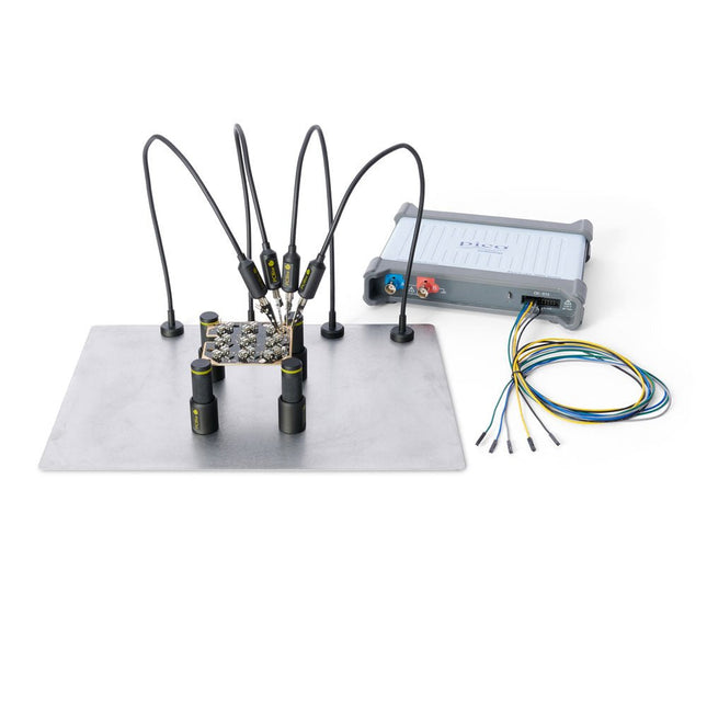
The minimalist design and the spring loaded test needle makes it possible to simultaneously measure on fine pitch components and nearby signals.
The probe is steady but yet flexible made for instant measurements or total hands-free operations together with your multimeter, logic analyzer or preferred tool.
The dual pin header connector fits directly on a 2.54 mm (0.100”) connector.
The SP10 comes with a powerful magnet in the base, as for all PCBite probes and holders which makes the probe easy to place and reposition.
Included
4x PCBite holder
1x Large base plate (A4)
4x PCBite probe with pin tipped test needle
4x Extra crown tipped test needle
1x Set of yellow insulation washers
5x Dupont to dupont test wire
2x Banana to dupont test wire
1x Microfiber cloth
Downloads
User Guide
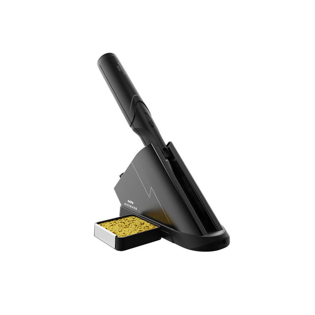
The Miniware Cordless Soldering Station TS1C (with integrated OLED screen and Bluetooth) is an intelligent soldering tool that heats up to 400°C in less than 20 seconds. Thanks to the built-in battery, the wireless soldering pen sits comfortably in the hand and is easy to use.
Features
New high-efficiency supercapacitor energy storage technology, 10,000-level charge and discharge times
Seperate design + true wireless, enjoy wireless soldering experience
BLE4.2 Bluetooth communication technology to realize remote control and setting
Standard PD2 20 V 45 W max power input, up to 36 W soldering power, can continuously solder more than 180 solder joints (0805) with a single full charge
Control station preheating to improve heating efficiency
3 expansion slots for accessories
Control Station
Standard PD2 20 V 45 W max power input, over current safety protection
128x64 pixel OLED screen, display soldering pen status in real time
Control station preheating, improve heating efficiency
Remote control and setting: temperature regulating, menu setting, viewing device info and status, etc.
Work as soldering stand and charging station
3 expansion slots for multiple expandable accessories like sponge slot
Soldering Pen
Built-in 750F high-efficiency energy storage supercapacitor, can be charged via control station (or via its USB Type-C interface in emergency cases)
36 W maximum heating power, can solder more than 180 solder joints (0805) continuously under a single full charge
Compatible with Miniware 3.5 mm audio interface soldering tips (TS80/80P soldering tip series)
Boost mode (holding the button on the pen)
Included
TS1C Soldering pen
TS1C Control station
Soldering tip (TS-B02)
Silicone cable
Sponge slot incl. sponge
Manual
The OWON XDM1241 is a fast, high-precision digital True RMS benchtop multimeter with a high-resolution 3.5-inch LCD and 50,000 counts. Its DC voltage accuracy is up to 0.05% and it can measure up to 65 values per second.
Features
3.5' high-resolution LCD (480x320 pixels)
55000 counts, DC voltage accuracy up to 0.05%
Up to 65 readings per second
Dual line display supported
Trend analysis accessible in chart mode
AC True RMS measurements (bandwidth: 20 Hz – 1 kHz)
SCPI support: Remote control the multimeter through PC software via USB port
Data record function, you can record the measured data into internal memory, and then read and process the recorded data with your computer.
Specifications
Measurement Range
Resolution
Accuracy
DC Voltage
50.000 mV
0.001 mV
0.1% +10
500.00 mV
0.01 mV
0.05% +5
5.0000 V
0.0001 V
0.05% +5
50.000 V
0.001 V
0.05% +5
500.00 V
0.01 V
0.1% +5
1000.0 V
0.1 V
0.1% +10
AC Voltage
500 mV~750 V
20 Hz~45 Hz
1% +30
45 Hz~65 Hz
0.5% +30
65 Hz~1 KHz
0.7% +30
DC Current
500 uA
0.01 uA
0.15% +20
5000 uA
0.1 uA
0.15% +10
50 mA
0.001 mA
0.15% +20
500 mA
0.01 mA
0.15% +10
5 A
0.0001 A
0.5% +10
10 A
0.001 A
0.5% +10
AC Current
500 uA~500 mA
20 Hz~1 KHz
0.5% +20
5 A-10 A
1.5% +20
Resistance
500 Ω
0.01 Ω
0.15% +10
5 KΩ
0.0001 KΩ
0.15% +5
50 KΩ
0.001 KΩ
0.15% +5
500 KΩ
0.01 KΩ
0.15% +5
5 MΩ
0.0001 MΩ
0.3% +5
50 MΩ
0.001 MΩ
1% +10
Frequency
10.000 Hz~60 MHz
/
±(0.2% +10)
Capacitance
50 nF~500 uF
/
2.5% +10
5 mF~50 mF
5% +10
Diode
3.0000 V
0.0001 V
/
Continuity
1000 Ω
0.1 Ω
Adjustable threshold
Temperature
K type, PT100
Max Display
55,000 counts
Data-logging Function
Logging Duration
15ms~9999.999s
Logging Length
1,000 points
Display
3.5' TFT LCD (480x320 pixels)
Power supply
Lithium battery via USB-C or 5 V DC input
Dimensions
235 x 88 x 65 mm
Weight
approx. 0.5 kg
Included
1x OWON XDM1241 Multimeter
2x Test leads
1x USB cable
1x USB to DC cord
1x Manual
Downloads
Programming Manual
PC Software
Funktionsweise, Aufbau und Handling eines Power Moduls
Das "Abc der Power Module" beinhaltet im ersten Schritt die wesentlichen Grundlagen, die bei der Auswahl und dem Einsatz eines Power Moduls notwendig sind. Das Buch beschreibt technische Zusammenhänge und Kenngrößen betreffend der Power Module sowie Berechnungsgrundlagen und Messtechniken.
Inhalt
Grundlagen
Dieses Kapitel beschreibt die Notwendigkeit eines Gleichspannungswandlers und dessen grundlegende Funktionsweise. Darüber hinaus werden verschiedene Möglichkeiten zur Realisierung eines Spannungsreglers dargestellt sowie die wesentlichen Vorteile eines Power Moduls benannt.
Schaltungstopologien
Hier werden dem Leser, die bei Power Modulen sehr häufig verwendeten Schaltungskonzepte, Abwärts- und Aufwärtstopologien, näher erläutert sowie über weitere Schaltungstopologien informiert.
Technik, Aufbau und Regelungstechnik
Vorgestellt wird der mechanische Aufbau eines Power Moduls, der einen wesentlichen Einfluss auf die EMV sowie das Wärmemanagement hat. Ferner sind diesem Kapitel Regelungs- und Schaltungstipps zu entnehmen.
Messverfahren
Aussagefähige Messergebnisse sind zur Beurteilung eines Power Moduls maßgeblich notwendig. In diesem Kapitel werden die entsprechenden Messpunkte und Messmethoden beschrieben.
Handling
Es werden die Punkte der Lagerung und den Umgang mit Power Modulen erläutert, ebenso wie deren Fertigungs- und Lötprozess.
Auswahl eines Power Moduls
Wichtige Parameter und Kriterien für die optimale Auswahl eines Power Moduls sind in dieser Rubrik nachzulesen.