The OWON SDS1102 is an affordable benchtop digital oscilloscope that combines solid performance with essential measurement features. This 2-channel oscilloscope offers a 100 MHz bandwidth, a 1 GS/s sampling rate, a 7-inch LCD display, and a 10 kpts memory depth, making it a practical choice for everyday electronics testing, troubleshooting, and education.
The SDS1102 features a simplified trigger system with level and edge triggering, making it easy to capture and analyze common signals. It is designed for applications that do not require deep memory or advanced trigger functions, offering a straightforward and cost-effective solution for basic signal analysis.
Features
Bandwidth: 100 MHz
2 channels
Sample rate: 1 GS/s
Ultra-thin body
7-inch high-res LCD
SCPI and LabVIEW supported
Specifications
Bandwidth
100 MHz
Horizontal Scale (s/div)
5 ns/div – 1000 s/div
Channel
2
Vertical Sensitivity
5 mV/div – 5 V/div (at input)
DC Gain Accuracy
3%
Vertical Resolution (A/D)
8 bits (2 channels simultaneously)
Input
Input Impedance
1 MΩ, 10 pF
Input Coupling
AC, DC, GND
Max Input Voltage
±400 V, CATI, CATII
Passive probes
х1; х10
Probe Attenuation Factor
х1; х10; х100; х1000
Trigger System
Trigger Mode
Auto, Normal, Single
Trigger Type
Edge, Video
Edge Trigger Source
CH1, CH2
Video Trigger
Sampling Type
Real-time
Sample Rate
1 GS/s
Equivalent Sample Rate
No
Wavelength
10K pts
Interpolation
sin(x)/x
Measurement and Mathematical Treatment System
Automatic Measurement
Vpp, Vavg, RMS, Frequency, Period, Vmax, Vmin, Vtop, Vbase, Width, Overshoot, Pre-shootRise time, Fall time, +Width, -Width, +Duty, -Duty, Delay A→B, Delay A→B, area, cycle area
Math Functions
Addition, Subtraction, Multiplication, Division, FFT
General Characteristics
Display type
7" color LCD
Display Resolution
800 x 480
Power
100-240 V, 45-440 Hz, <15 W
Dimensions
301 x 70 x 152 mm
Weight
1.1 kg
Included
1x OWON SDS1102 Oscilloscope
2x Oscilloscope probes
1x Probe adjust
1x Mains power cord
1x USB cable
1x CD-Rom
1x Quick guide
Downloads
Quick Guide
Manual
PC Software
SCPI Commands
Auch heute noch klingen Röhrenverstärker zweifellos phantastisch, möglicherweise sogar noch faszinierender als in früheren Zeiten. Gegenwärtig verfügen wir über moderne Bauteile und Materialien, wie z. B. Ringkern-Ausgangsübertrager, ausgesprochen hochwertige Widerstände, Kondensatoren und allerlei, die Übertragungseigenschaften nicht beeinflussende Drahtsorten. Hinzu kommen hochqualitative Tonträger wie CD-Spieler und ebenso hochwertige Lautsprecher, die die überragenden klanglichen Eigenschaften von Röhrenverstärkern erst richtig zur Geltung kommen lassen.
Das vorliegende Buch behandelt zwar auch die Theorie, mehr jedoch richtet sich die Aufmerksamkeit auf die Entwurfsphase dieser Verstärker, innerhalb derer die projektierten Eigenschaften und gestellten Anforderungen formuliert werden müssen. In welchem Zusammenhang stehen subjektive und objektive Kriterien? Welche Schaltungsvarianten entwickeln überzeugende klangliche Eigenschaften und warum? Welche Probleme sind zu lösen, wenn man einen Röhrenverstärker entwickeln und diesen käuflich vertreiben möchte? Was genau sagen uns messtechnische Analysen eines Gerätes und wie sind die gewonnenen Ergebnisse zu interpretieren, welche Aussagekraft besitzen sie? Aufgrund der überwältigenden Rechengeschwindigkeit moderner Computer sind wir in der Lage, ausgesprochen präzise Messungen mit vergleichsweise geringem Aufwand innerhalb kürzester Zeit durchzuführen. Aber: Wie lassen sich diese Möglichkeiten sinnvoll auf Röhrenverstärker anwenden? Bislang war die messtechnische Erfassung des Frequenzganges, der Ausgangsleistung und des Klirrverhaltens eines Verstärkers ausreichend, um sich ein hinreichend aussagekräftiges Bild von dessen Übertragungseigenschaften zu verschaffen. Es muss aber die Frage gestellt werden, ob die Erfassung solcher Messwerte tatsächlich genügt zu ermitteln, wie unser Ohr die reproduzierten Klangereignisse wahrnimmt, oder ob wir nicht besser mit realen musikalischen, dynamischen Signalen anstelle von statischen Messfrequenzen arbeiten sollten. Der Autor entwirft in diesem Buch Kriterien für zukünftige Messverfahren, die die Eigenschaften unseres Gehörs mit berücksichtigen und die damit zu neuen Einsichten und Erkenntnissen führen.
Dieses Buch schildert die Zusammenhänge überwiegend praxisorientiert und vermittelt eine neue Perspektive, gewissermaßen einen von außen gerichteten Blick auf den Röhrenverstärker. Dabei wird bereits Bekanntes mit einbezogen und in anschaulicher Weise in neue Zusammenhänge integriert.
Contents
Basic principles
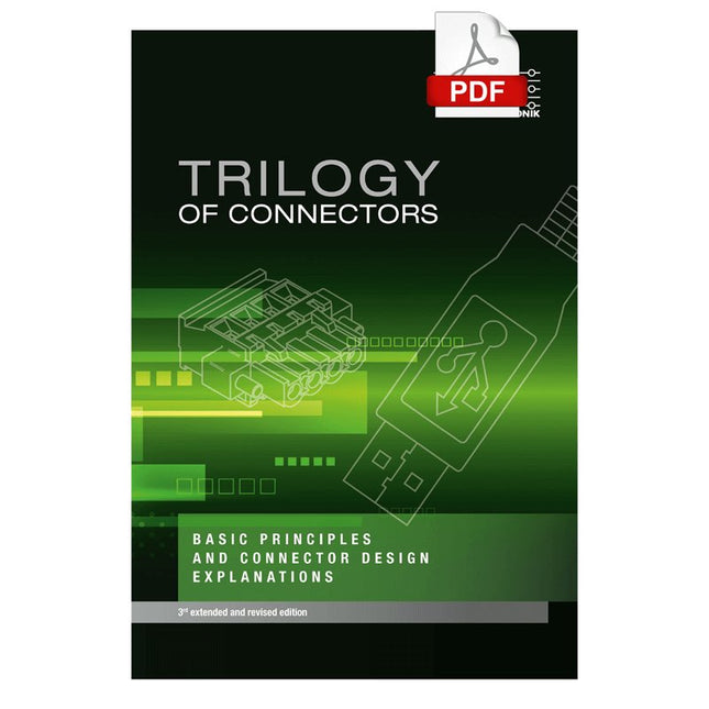
A connector is an electromechanical system that provides a separable connection between two subsystems of an electronic device without an unacceptable effect on the performance of the device. It will be shown that there are a lot of complex parameters to handle properly to make this statement true.
Design / Selection / Assembly
This chapter provides an overview of design and material requirements for contact finishes, contact springs and connector housings as well as the major degradation mechanisms for these connector components. To complete this chapter, material selection criteria for each will also be reviewed. Additionally the Level of Interconnection (LOI) was integrated into this chapter as it addresses, where the connector is used within an electronic system and therefore influences the requirements and durability of the connector depending on its use.
Applications
This chapter is heading to the practical work and shows how customers use connectors in their applications to offer some possibilities and to ease your daily work. Additionally it contains some special topics like tin-whisker or impedance of ZIF cable to offer you extended background knowledge.
Niemand twijfelt er aan dat buizenversterkers een opmerkelijk mooi geluid produceren. Ze klinken levendig, diep en doortekend; het klankbeeld is zeer aangenaam en dynamisch schijnen ze nagenoeg geen beperkingen te kennen.Via een systematisch theoretisch onderzoek gaat de auteur na waardoor deze fraaie eigenschappen ontstaan. Hij ontwikkelt nieuwe modellen voor versterkerbuizen en transformatoren, waardoor het mogelijk wordt om op voorhand, tijdens het ontwerp, al te bepalen wat de eigenschappen van de buizenversterker worden. De koppeling tussen eindbuizen en de uitgangstransformator wordt diepgaand gemodelleerd. Daarbij ontstaan nieuwe inzichten in een uitzonderlijk soort vervorming: de dynamische dempingsfactor vervorming (DDFD).
Via rekenmodellen in het complexe domein worden vooral de eigenschappen in de grenzen van het hoorbare gebied (tussen 20 Hz en 20 kHz) onderzocht en ontstaan stabiliteitsvoorwaarden waar de versterker minstens aan moet voldoen. In versterkers wordt vaak tegenkoppeling toegepast, die uitgebreid wordt gemodelleerd en waarvan de gehoorsmatige gevolgen diepgaand worden besproken.Vervolgens wordt een fraaie selectie van bijzondere buizenversterkers besproken.
Kenmerkend in dit boek is dat de auteur niet alleen technisch schrijft, maar verhalend laat zien dat het ontwikkelen van buizenversterkers ook ingrijpt in je dagelijkse leven; zelfs het nut van patenten wordt besproken. Samenvattend: nieuwe theorieën en oplossingen voor een perfecte audiokwaliteit met buizenversterkers. Zowel de zelfbouwer als diegene die kennis en inzicht wil verwerven zal dit boek met plezier ter hand nemen.
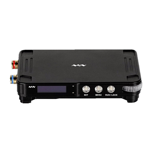
MDP-P906 has a built-in cooling fan, and maximum output power of up to 300 W, which meets a wider range of testing needs and application scenarios. Through 2.4 GHz wireless communication, it can be connected to MDP-M01 Smart Digital Monitor module to realize the free combination of multiple channels of 300 W per channel.
MDP-P906 has the index, stability and reliability comparable to a professional power supply. It can output pure current, and provide powerful functions such as programmable output, timing output, timing control, automatic compensation, boost mode, etc., making itself a real cost-effective, smart and customized programmable linear DC power supply.
MDP-P906 adopts a precision CNC machined aluminum alloy shell, with fine workmanship, novel, mini and beautiful appearance, it completely subverts the rigid image of traditional desktop power supply. With stackable modular design and wireless communication function, MDP-P906 can work independently or paired, both on the workbench, and be carried out for on-site maintenance. MDP-P906 is a perfect solution for electronic engineer, especially field application engineers to meet different needs of power sources.
Built-in silent cooling fan, instant cooling, ensure a stable and efficient output!
Smart linear compensation, constant voltage & constant current
Positive & negative output, series boost, parallel current sharing
Applications
Universal tests and teaching experiments in R&D laboratory
Maintenance of digital products
Property verification and fault diagnosis of devices and circuits
Emergency power supply for model airplanes and vehicles
Power supply testing of RF and microwave circuits or modules
Quality control and quality inspection
Supply purified power for high-accuracy digital-analog hybrid circuits and Hi-Fi audio devices
Specifications
Input
DC 4.2-30 V/14 A (Max)QC 3.0/PD2.0, 20 V/5 A (Max)
Output
0-30 V/0-10 A, 300 W (Max)
Conversion efficiency
95%
Output resolution
10 mV/2 mA, up to 1 mV/1 mA via Display Control module
Output accuracy
0.03%+5 mV0.05%+2 mV
Adjustment rate
Load adjustment rate <±0.01%Power adjustment rate <±0.01%
Ripple and noise
<250 uVrms, 3 mVpp; 2 mArms
Transient response
<4 uS
Safety protections
Input over-voltage, under-voltage, reverse connection protection, output over-current, back-flow protection and over-temperature protection
Others
Automatically shut-down and enter micro-power modeSupport USB firmware upgrade
Dimensions
112 x 66 x 20 mm
Weight
181 g
Included
1x MDP-P906 Digital Power Supply
2x Output Cable
1x User Manual
Downloads
User Manual v1.1
Firmware v1.32
Highlights
Output Frequency (Sine): 50 MHz
Output Frequency (Square): 15 MHz
Channels: 2
Arbitrary Waveform Length: 16 Mpts
Features
Unique SiFi II (Signal Fidelity II) technology: generate the arbitrary waveforms point by point; recover the signal without distortion; sample rate accurate and adjustable; jitter of all the output waveforms (including Sine, Pulse, etc.) as low as 200 ps
16 Mpts memory depth per channel for arbitrary waveforms
Standard dual-channel with the same performance, equivalent to two independent signal sources
High frequency stability: ±1 ppm; low phase noise: -105 dBc/Hz
Built-in high-order harmonic generator (at most 8-order harmonics)
Built-in 7 digits/s, 240 MHz bandwidth full featured frequency counter
Up to 160 built-in arbitrary waveforms, covering the common signals in engineering application, medical electronics, auto electronics, math processing, and other various fields
Sample rate up to 250 MSa/s, vertical resolution 16 bits
Arbitrary waveform sequence editing function available; arbitrary waveforms also can be generated through the PC software
Various analog and digital modulation functions: AM, FM, PM, ASK, FSK, PSK, and PWM.
Standard waveform combine function, capable of outputting specified waveforms combined with the basic waveforms
Standard channel tracking function, when enabled, all the parameters of both channels are updated based on users' configurations
Standard interface: USB Host&Device and LAN (LXI Core 2011 Device); USB-GPIB function supported
4.3'' TFT
Included
1x Rigol DG2052 Function/Arbitrary Waveform Generator
1x Power cord
1x USB cable
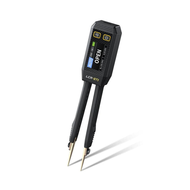
The FNIRSI LCR-ST1 is a compact, multifunctional, and smart LCR tester that supports automatic measurements of resistance, capacitance, inductance, diode testing, and continuity.
Its 1.14-inch color display combined with a convenient magnetic adsorption function enhances ease of use, while the built-in 250 mAh lithium battery ensures long-lasting performance. The device supports three frequency ranges (100 Hz, 1 kHz and 10 kHz) and offers 0.3 V and 0.6 V RMS test levels for versatile testing applications.
The unique tweezer-shaped design of the LCR-ST1 is ideal for delicate tasks in confined spaces and enables fast and accurate testing of electronic components. Its light weight and portable design make it an invaluable tool for both field and laboratory use.
Whether you are an experienced engineer or just starting out in electronics, the LCR-ST1 delivers reliable and accurate measurement results, allowing you to complete your tasks with greater efficiency and precision.
Features
Offers 3 test frequencies (100 Hz, 1 kHz, 10 kHz) and 2 test voltage levels.
Features automatic component identification for faster and more reliable measurements.
High-resolution 1.14-inch color display for clear readouts.
Supports automatic data recording and storage.
The tweezer tips are made from gold-plated brass for enhanced durability and conductivity.
Specifications
Resistance Range
10 mΩ – 10 MΩ
Capacitance Range
1 pF – 22 mF
Inductance Range
1 μh – 10 H
Diode
On voltage 0.7 V
Frequency Test
100 Hz, 1k Hz, 10 KHz
Level Test
0.3 V, 0.6 V RMS
Parameter Display
ESR, D value, Q value, Z value, X value
Display
1.14" HD color screen
Charging Interface
USB-C, 5 V/1 A
Power Supply
Built-in 250 mAh lithium battery
Auto Recognition Measurement
Yes
Replaceable Tweezer Head
Yes
Auto Shutdown
Yes
Data Hold
Yes
History Record
Connect to PC to view and export
Dimensions
28 x 19 x 150 mm
Weight
41 g
Included
1x LCR-ST1 SMD Tweezers
2x Hook Tips
1x Magnetic Patch
1x USB cable
1x Tool bag
1x Manual
Downloads
Manual
Firmware V1.6
This kit includes iFixit's widest assortment of bits, complete with every driver head you’ll need to tackle any repair or DIY project. It includes standard bits like Phillips and Flathead in a full range of sizes to handle everything from precision electronics repair to home DIY projects. And it wouldn’t be an iFixit bit set if it didn’t include all the exotic bits from Pentalobes for Apple iPhone and MacBook repair to Gamebits for your vintage Nintendo consoles.
All of the next-gen bit sets have been re-designed in order to maximize convenience and usability. The bit set lid is held in place with magnets to increase product lifespan (no more broken hinges or clasps) and also mounts to the back of the bit set case to keep it out of the way while you do your work. If you need help keeping your screws and parts organized, you can use the lid’s integrated sorting tray. The 4 mm bits have been adjusted and have now a longer neck for a deeper and more precise reach.
Toolkit Includes
Easy-to-Open Magnetized Case
Lid with Built-in Sorting Tray
4 mm Aluminum Bit Driver
1/4' Aluminum Bit Driver
4 mm Screwdriver Bits
Phillips - 000, 00, 0
Flathead - 1, 1.5, 2, 2.5, 3, 3.5 mm
Torx - T2, T3, T4, T5
Torx Security - TR6, TR7, TR8
Pentalobe - P2, P5, P6
JIS - 000, 00, 0, 1
Hex - 0.7, 0.9, 1.3, 1.5 mm
Hex Security - 2, 2.5, 3, 3.5 mm
Tri-point - Y000, Y00, Y0, Y1
Nut driver - 2.5, 3, 3.5, 4, 4.5, 5, 5.5 mm
Gamebit - 3.8, 4.5 mm
Spanner - 4, 6
Triangle - 2, 2.2, 2.6, 3 mm
Oval Bit
iPhone Standoff Bit
Sim Eject Bit
Magnetic Pickup Bit
1/4' Screwdriver Bits
Phillips - 1, 2, 3
Flathead - 4, 5, 6, 7, 8 mm
Hex Security - 4, 5, 6, 7, 8 mm
Hex Security SAE - 1/8, 9/64, 5/32, 3/16, 7/32, 1/4
Pozidriv - PZ0, PZ1, PZ2, PZ3
Torq-set - 6, 8, 10
Spanner - 8, 10, 12
Square - 0, 1, 2, 3
Spline - M5, M6, M8
Torx Security - TR9, TR10, TR15, TR20, TR25, TR27, TR30, TR35, TR40
Tri-wing 1, 2, 3, 4
Clutch 1, 2, 3
Schrader Valve
Hook Drive
1/4' to 4 mm Adapter
1/4' Driver to 1/4' Socket
1/4' Driver to 3/8' Socket
1/4' Socket to 1/4' Driver
Specifications
Bit Metal: 6150 Steel
Driver Material: Anodized Aluminum
Case Material: ABS
Foam: EVA
Highlights
Output Frequency (Sine): 70 MHz
Output Frequency (Square): 20 MHz
Channels: 2
Arbitrary Waveform Length: 16 Mpts
Features
Unique SiFi II (Signal Fidelity II) technology: generate the arbitrary waveforms point by point; recover the signal without distortion; sample rate accurate and adjustable; jitter of all the output waveforms (including Sine, Pulse, etc.) as low as 200 ps
16 Mpts memory depth per channel for arbitrary waveforms
Standard dual-channel with the same performance, equivalent to two independent signal sources
High frequency stability: ±1 ppm; low phase noise: -105 dBc/Hz
Built-in high-order harmonic generator (at most 8-order harmonics)
Built-in 7 digits/s, 240 MHz bandwidth full featured frequency counter
Up to 160 built-in arbitrary waveforms, covering the common signals in engineering application, medical electronics, auto electronics, math processing, and other various fields
Sample rate up to 250 MSa/s, vertical resolution 16 bits
Arbitrary waveform sequence editing function available; arbitrary waveforms also can be generated through the PC software
Various analog and digital modulation functions: AM, FM, PM, ASK, FSK, PSK, and PWM.
Standard waveform combine function, capable of outputting specified waveforms combined with the basic waveforms
Standard channel tracking function, when enabled, all the parameters of both channels are updated based on users' configurations
Standard interface: USB Host&Device and LAN (LXI Core 2011 Device); USB-GPIB function supported
4.3'' TFT
Included
1x Rigol DG2072 Function/Arbitrary Waveform Generator
1x Power cord
1x USB cable
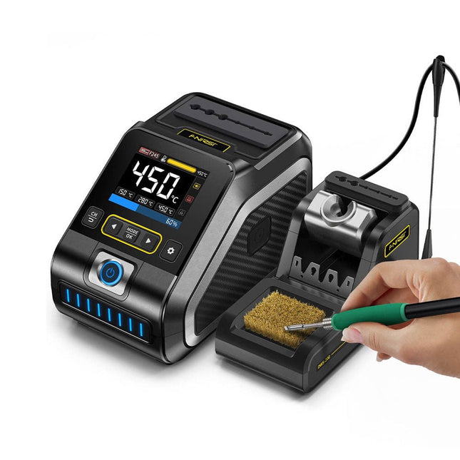
The FNIRSI DWS-200 is a powerful 200 W smart soldering station, ideal for electronic soldering applications. Powered by a switch-mode power supply, it operates smoothly with a wide voltage input range of 100-240 V. The station provides an adjustable temperature range from 100°C to 450°C (212°F to 842°F) and allows for easy switching between °C and °F.
To enhance efficiency, it supports up to three preset temperature values and can connect to a soldering iron stand for standby mode activation. The station also features a dynamic temperature curve mode for real-time data monitoring, ensuring precise and consistent performance in demanding soldering tasks.
Features
Maximum power output of 200 W, allowing for fast heating
Wide adaptive voltage input of 100-240 V
2.8" HD color TFT display with intelligent control
Multiple preset groups to switch between different settings quickly
Supports F245 and F210 soldering handle types, offering flexibility for different soldering applications
Real-time sleep mode to extend the life of the soldering tip
Multi-mode real-time monitoring for power and temperature status, enhancing safety and precision
Specifications
Peak Power
200 W (max)
Temperature Range
100°C~450°C (212°F~842°F)
Display
2.8" TFT HD Color Screen
Heating Time
1 sec
Melting Time
3 sec
Input Voltage
100-240 V (AC)
Input Fuse
3 A
Soldering Handle Type
F245
Dimensions (Station)
156 x 96 x 103 mm
Weight (Station)
475 g
Included
1x FNIRSI DWS-200 Soldering Station
1x Soldering Handle F245
6x Soldering Tips (B, KU, K, C2, I, JS)
1x Connecting Cable
2x Helping Hands
1x Power Cable (EU)
Downloads
Manual
Firmware V1.3
UNI-T UPO1202CS is a multifunctional, low-cost 2-channel digital phosphor oscilloscope with 200 MHz bandwidth and 1 GSa/s sampling rate. It can be widely used in the fields of electronic and electrical design, debugging, education and industrial design.
UPO1000CS series adopts parallel digital signal processing technology, which greatly improves the data processing speed and waveform capture rate. The original Ultra Phosphor technology can present the cumulative effect of the tested signal as a multi-layered afterglow. Compared with traditional digital storage oscilloscopes, the persistence of digital phosphor oscilloscopes can present three-dimensional waveform data of amplitude, time and signal intensity. Fast Acquire technology can accurately capture abnormal events such as video, jitter, noise and runt signals.
Specifications
UPO1102CS
UPO1202CS
Bandwidth
100 MHz
200 MHz
Analog channels
2
2
Sampling rate
1 GSa/s
1 GSa/s
Storage depth
56 Mpts per channel
56 Mpts per channel
Rise time
≤3.5ns
≤1.8ns
Capture rate
500,000 wfms/s
500,000 wfms/s
Waveform record
100,000 frames
100,000 frames
Features
7' WVGA (800 x 480) TFT LCD
Ultra Phosphor super fluorescent display effect, up to 256 levels of gray display
Support RS232, I²C, SPI, CAN and LIN trigger
Innovative RS232, I²C, SPI, CAN and LIN hardware decoding
Vertical scale: 1 mV/div-20 V/div
Low background noise: <100 μVrms
1M points enhanced FFT function. Support frequency setting, waterfall diagram, detection setting and marker measurement etc
36 kinds of waveform parameters can be automatically measured
Rich trigger functions (edge, pulse width, video, slope, runt, overshoot, delay, timeout, duration, setup and hold, Nth edge and pattern trigger)
Multi-Scopes support dual-channel independent trigger fluorescence display
Multi-channel independent 7-bit hardware frequency counter
DVM supports dual-channel independent AC and DC true RMS measurement
Waveform arithmetic functions (FFT, +, -, ×, ÷, digital filtering, logic operations, and advanced operations)
Rich interfaces: USB Host, USB Device, LAN, EXT Trig, AUX Out (Trig Out, Pass/Fail)
Support SCPI programmable instrument standard command
Support WEB access and control
Downloads
Datasheet
Programming Manual
User's Manual
Quick Start Guide
Software