
Search results for "wireless OR high OR power OR transmission"
-
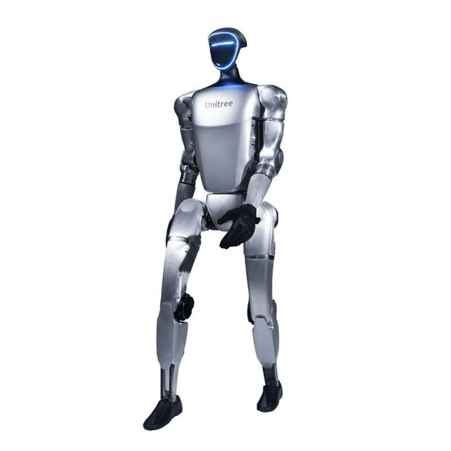
Unitree Unitree G1 Humanoid Robot
The Unitree G1 is a modern humanoid robot that impresses with its remarkable flexibility and advanced technology. With an exceptionally wide range of joint movement and up to 43 joint motors, it exceeds the agility of a typical human. Powered by imitation learning and reinforcement learning, its robotic systems are continuously developed and optimized through artificial intelligence. One of the G1's most impressive features is its ability to autonomously move into a walking position as soon as it touches the ground – no external assistance required! It can immediately start moving, demonstrating a high level of independence and adaptability. The G1 is also equipped with a force-controlled, highly dexterous hand that operates with both sensitivity and precision, thanks to its combination of force and position control. This hand closely mimics human movements, allowing for precise object manipulation. Features Intel RealSense D435 Depth Camera Livox MID-360 3D LiDAR Microphone array (noise and echo cancellation) 5 W stereo speaker Extra large quick release battery Single arm degrees of freedom (shoulder 2 + elbow 2) Hollow joint wiring of the whole machine (no external cables) Maximum torque at joints 120 N.m Single leg degrees of freedom (hip 3, knee 1, ankle 2) Moving speed of 2 m/s Specifications Height, Width and Thickness (Stand) 1320 x 450 x 200 mm Height, Width and Thickness (Fold) 690 x 450 x 300 mm Weight (with Battery) approx. 35 kg Total Degrees of Freedom(Joint Freedom 23 Single Leg Degrees of Freedom 6 Waist Degrees of Freedom 1 Single Arm Degrees of Freedom 5 Joint output bearing Industrial grade crossed roller bearings (high precision, high load capacity) Joint motor Low inertia high-speed internal rotor PMSM (Permanent Magnet Synchronous Motor – better response speed and heat dissipation) Maximum Torque of Knee Joint 90 N.m Arm Maximum Load approx. 2 kg Calf + Thigh Length 0.6 m Arm Span approx. 0.45 m Extra Large Joint Movement Space • Waist joint: Z ±155°• Knee joint: 0~165°• Hip joint: P ±154°, R -30~+170°, Y ±158° Full Joint Hollow Electrical Routing Yes Joint Encoder Dual encoder Cooling System Local air cooling Power Supply 13 string Lithium battery Basic Computing Power 8-core high-performance CPU Sensing Sensor Depth Camera + 3D LiDAR Microphones 4 Microphone Array Speaker 5 W stereo speaker Wireless WiFi 6, Bluetooth 5.2 Smart Battery (Quick Release) 9000 mAh Charger 54 V/5 A Manual Controller Yes Battery Life approx. 2 hours Upgraded Intelligent OTA Yes
€ 24.999,00
Best Price
-

Siglent Siglent SSA3032X Plus Spectrum Analyzer (9 kHz – 3.2 GHz)
The Siglent SSA3032X Plus spectrum analyzer is a powerful and flexible tool for RF signal and network analysis. With a frequency range of 3.2 GHz, the analyzer delivers reliable automatic measurements and multiple modes of operation: spectrum analyzer the base, optional functions include RF power measurement, vector signal modulation analysis, reflection measurement, and EMI test. Applications include broadcast monitoring/evaluation, site surveying, S-parameter measurement, analog/digital modulation analysis, EMI pre-compliance test, research and development, education, production, and maintenance. Features Spectrum Analyzer Frequency Range from 9 kHz to 3.2 GHz –161 dBm/Hz Displayed Average Noise Level (Typ.) –98 dBc/Hz. @ 10 kHz Offset Phase Noise (1 GHz, Typ.) Level Measurement Uncertainty <0.7 dB (Typ.) 1 Hz Minimum Resolution Bandwidth (RBW) Preamplifier (Std.) Tracking Generator (incl. free of charge) Analog and Digital Signal Modulation Analysis Mode (opt.) Reflection Measurement Kit (opt.) EMI Filter and Quasi-Peak Detector Kit (opt.) Advanced Measurement Kit (opt.) 10.1-inch Multi-Touch Screen , Mouse and Keyboard supported Web Browser Remote Control on PC and Mobile Terminals and File Operation Specifications SSA3015X Plus SSA3021X Plus SSA3032X Plus SSA3075X Plus Frequency Range 9 kHz ~ 1.5 GHz 9 kHz ~ 2.1 GHz 9 kHz ~ 3.2 GHz 9 kHz ~ 7.5 GHz Resolution Bandwidth 1 Hz ~ 1 MHz 1 Hz ~ 1 MHz 1 Hz ~ 1 MHz 1 Hz ~ 3 MHz Phase Noise <–99 dBc/Hz <–98 dBc/Hz <–98 dBc/Hz <–98 dBc/Hz Total Amplitude Accuracy <1.2 dB <0.7 dB <0.7 dB <0.7 dB Display Average Noise Level –156 dBm/Hz –161 dBm/Hz –161 dBm/Hz –165 dBm/Hz Included Siglent SSA3032X Plus spectrum analyzer USB cable Power cord Quick start guide Downloads Datasheet Manual Documentation Firmware
€ 2.951,19
-

Elektor Labs Elektor Low-Noise Lab Power Supply
The Elektor Low-Noise Lab Power Supply is a fully analogue, adjustable, medium-power symmetrical bench supply that contains no switching or digital components. It provides an output voltage adjustable between 0 V and ±22 V, and an output current adjustable from 0 A to 1 A. Because it avoids any form of switching circuitry, the design delivers extremely low noise. To display both output voltages and currents, four miniature moving-coil panel meters are used. Most modern laboratory power supplies and AC adapters employ switch-mode techniques. Even the best examples inevitably exhibit high-frequency ripple and other switching artefacts on their output, which can interfere with the testing of sensitive analogue circuits and disturb low-level measurements. To overcome this, the concept here is a completely analogue power supply. Although less efficient than its switch-mode counterparts, the reduced efficiency is of little importance for test-bench use and ensures cleaner, more reliable measurement results. Because many analogue circuits require a symmetrical supply, this design delivers positive and negative output voltages of equal magnitude. A small amount of adjustment is available to compensate for any imbalance. Naturally, a variable current-limit function is also included. The kit includes the components required to build the power supply, except for the transformers. Specifications Output Voltage 0…+22 V, 0, −22 V Output Current 0…+1 A, 0…−1 A Noise −85 dBV, (at 0.95 A/20 V, B = 22 kHz) −84 dBV (at 0.95 A/20 V, B > 500 kHz) Ripple 50 µVRMS (at 950 mA/20 V, B = 22 kHz, mainly 100 Hz component) Included 3x PCBs: Regulator (PCB-1), Mains Filter (PCB-2) and Transformer (PCB-3) All the components except the AC transformers 4x moving-coil meters Additional parts for wiring (wires, banana sockets, IEC Power entry module, etc.) Not included The three AC transformers An enclosure Parts List For the Regulator PCB (240386-1) Resistors (250 mW, 1%) R1 = 12 Ω R2, R8, R37, R62 = 1 MΩ R3, R7, R10, R13, R17, R20, R22, R30, R35, R42, R45, R47, R55, R60 = 100 Ω, 600 mW R4, R5 = 4.7 kΩ R6 = 100 kΩ R9, R12, R14, R36, R38, R39, R61, R63, R66, R72, R78, R79 = 10.0 kΩ, 600 mW R11 = 9.76 kΩ, 600 mW R15, R40 = 44.2 kΩ, 600 mW R16, R41, R77 = 1 kΩ R18, R43 = 1.5 kΩ, 1 W, 5% R19, R44 = 470 Ω, 1 W, 5% R21, R46 = 330 Ω, 600 mW R23, R24, R48, R49 = 1.0 Ω, 1 W R25, R50 = 1 kΩ, 1 W, 5% R26, R28, R51, R53 = 1.000 kΩ 0.1%, 15 ppm/C R27, R29, R52, R54 = 10.00 kΩ 0.1%, 15 ppm/C R31, R56 = 1.2 kΩ, 1 W, 5% R32, R57 = 47 kΩ R33, R58 = 270 Ω R34, R59 = 27 kΩ R64, R69 = 12.0 kΩ R65 = 3.0 kΩ, 600 mW R67, R80 = 470 Ω, 600 mW R68, R70 = 6.8 kΩ, 600 mW R71 = 30.0 kΩ,, 600 mW R73, R74, R75, R76 = 10 MΩ P1, P2, P3 = 10 kΩ, 200 mW, 20%, potentiometer, 1 turns, single, lin., panel mount P4, P5 = 500 Ω, 500 mW, 10%, trimmer, 25 turns, 3296Y-1-501LF Bourns P6, P7 = 10 kΩ, 500 mW, 10%, trimmer, 25 turns, 3296Y-1-501LF Bourns Capacitors C1 = 100 nF, 50 V, 10%, ceramic X7R, LS 5 mm C2, C3, C6, C7, C30 = 10 µF, 63V, 20%, LS 2.5 mm, 3000hours@105°C C4, C5, C8, C9, C13, C14, C18, C19, C23, C24, C28, C29, C31, C32, C38, C39 = 100 nF, 250 V, 10%, PET, LS 7.5 mm C10, C20 = 47 nF, 100 V, 5%, PET, LS 5 mm C11, C21 = 10 nF, 100 V, 5%, PET, LS 5 mm C12, C22 = 220 µF, 35 V, 20%, 0.024 Ω, LS2.5/3.5 mm, Ir 3.4 A, 2000hours@125°C, polymer C15, C25 = 120 µF, 50 V, 20%, ESR 0.02 Ω, Diam. 10 mm max., LS 5 mm C16, C26 = 15 nF, 100 V, 5%, PET, LS 5 mm C17, C27 = 47 nF, 100 V, 5%, PET, LS 5 mm C33, C34 = 22 µF, 50 V, 20%, LS 2 mm, 10000 hours @ 105°C C35, C36, C44, C45 = 1 µF, 100 V, 10%, LS 5 mm, ceramic X7R C37 = 100 uF, 50 V, 20%. LS 3.5 mm C40, C41, C42, C43, C46, C47, C48, C49 = 1000 µF, 50 V, 20%, LS 5/7.5 mm, Ir 3.32 A, 10000hours@105°C, D 16 mm C50, C51, C52, C53 = 47 nF, 100 V, 10%, ceramic X7R, LS 5 mm Inductors L1, L2 = 4.7 µH, 3.2 A, 0.033 Ω, LS 5 mm, RLB0914-4R7ML Bourns L3 = Commom mode choke, 14.5 mH, 3 A, SSRH24NH-30145 Kemet Semiconductors D1, D2, D3, D4, D5, D9, D10, D11, D15 = BAT85, DO-34 D6, D7, D12, D13 = SR560, DO-201AD D8, D14, D16 = 1N4148, DO-35 D17 = Zenerdiode, 5.6 V, 0.5 W, DO-41 D18, D19 = 1N4004, DO-41 D20, D21 D22, D23 = V30100CI-M3/P, dual common cathode, TO-220 D24 = Zener diode, 30 V, 1 W, DO-41 LED1, LED2 = LED, red, T-1 (3 mm) LED3, LED4 = LED, green, T-1 (3 mm) TVS1, TVS2 = BZW50-33B, R6 T1, T2, T4 = BC337.25, TO-92 T3 = NJW0302G, TO-3P T5, T6, T8 = BC327.25, TO-92 T7 = NJW0281G, TO-3P T9 = BD139, TO-126 (SOT-32) IC1 = LM334Z, TO-92 IC2 = LM4040AIZ-5.0/NOPB, TO-92 (TO-226AA-3) IC3, IC4 = OPA2992IDR, SOIC-8 IC5, IC6 = OPA4992IDR, SOIC-14 IC7 = OPA992IDBVR, SOT-23-5 IC8 = LM339N, DIP-14 IC9 = LM317, TO-220 IC10 = LM337, TO-220 Others F1, F2 = 5×20 mm fuse, 1.6 A, fast acting HS1, HS2 = Heatsink MC33271 (for T3/T7), 2.7°C/W, PCB mount, height 63.5 mm K1, K4 = 3-way screw terminal block, LS 3.5 mm, max. 1.5 mm² K2, K3 = 3-way screw terminal block, LS 3.5 mm, max. 1 mm² M1, M3 = Moving coil meter, Range 30 V, type 91C4, 45×45 mm M2, M4 = Moving coil meter, Range 1 A, type 91C4, 45×45 mm² RE1 = Relay DPDT,5V, UA2-5NU Miscellaneous 3× 3-way screw terminal block, LS 3.5 mm, max. 1 mm² (for P1, P2, P3) 4× Pin header, 1×2, vertical, pitch 2.54 mm (for LED1, LED2, LED3, LED4) 4× Pin socket, 1×2, vertical. pitch 2.54 mm (for LED1, LED2, LED3, LED4) 2× Heatsink FK222SA220, 20°C/W, PCB mount (for IC9 & IC10) 2× Mica thermal pad for TO-220, 12×18×0.05 mm (for IC9 & IC10) 2× Insulating bushing IB 6, TO-220 (for IC9 & IC10) 2× Ceramic thermal pad, 23×20×2 mm (for T3 & T7) 2× PCB Fuse Holder, for 5×20 mm fuse, 10 A (for F1, F2) 2× Cover for PCB Fuse Holder, transparent (for F1, F2) 2× 2-way screw terminal block, LS 3.5 mm, max. 1 mm² (for M1 & M3) 2× 2-way screw terminal block, LS 3.5 mm, max. 1.5 mm² (for M2 & M4) 8× M3 solder lug, thickness 0.35 mm (for M1…M4) M4 solder lug, thickness 0.35 mm (to connect 4 mm banana connectors) Screened cable, 1 pair, 2×24 AWG/0.22 mm², 1 m (for P1, P2 & P3) IC socket, DIP, 14 contacts (for IC8) M3 washer, plain, steel M3 screw, 16 mm, steel, pan head M3 nut M3 spring washer 50 mm M3 standoff, steel, male-female 12 mm M3 standoff, steel, male-female 10 mm M3 standoff, steel, male-female M3 screw, 8 mm, steel, pan head For the Mains Fiter PCB (240386-2) Resistor R1 = 220 kΩ, 1 W, 500 V, 5% Capacitors C1, C2 = 470 nF, 305 VAC, Class X2, 11 × 27 mm max., LS 15/22.5 mm C3, C4, C5, C6 = 2.2 nF, 300 VAC, Class Y2, 13 × 4 mm, LS 10 mm, PP Inductors L1, L2 = Common-mode choke, 6.8 mH, 1.7 A, TDK B82732R2172B030 Semiconductor MOV1 = TVS varistor, 300 VAC, S14K300 (230 VAC, B72214S0301K101) and SK14K150 (150 VAC, B72214S0151K101) Others K1, K2 = 3-way screw terminal block, LS 7.62 mm F1 = Time-delay fuse, 0.5 A (230 VAC) or 1 A (115 VAC) Miscellaneous 1× Fuse holder, 5×20 mm, 10 A, 500 VAC 1× Transparent fuse cover 4× 10 mm M3 standoff, steel, male–female 4× M3 screw, 8 mm, steel, pan head 4× M3 nut For the Transformer PCB (240386-3) Resistors R1, R2 = 2.7 kΩ, 600 mW, 1% R3 = 10.0 kΩ, 600 mW, 1% Capacitor C1 = 220 µF, 50 V, 20%, Ø10 mm, LS 5 mm, 4000 h @ 105°C Transformers (not included in this kit!) TR1, TR2, TR3 = 2×7 V, 25 VA, PCB-mounted toroid, 70060K Talema Semiconductors D1–D4 = 1N4148, DO-35 D5, D6 = 1N4004, DO-41 D7 = Zener 5.6 V, 1.3 W, DO-41 LED1 = LED, red, T-1 (3 mm) IC1, IC2 = MOC8021M, CTR ≥ 1000%, DIP-6 Others F1, F2, F3 = 160 mA time-delay fuse (230 VAC) or 315 mA time-delay fuse (115 VAC) K1 = 2-way screw terminal block, LS 7.62 mm K2 = 3-way screw terminal block, LS 3.5 mm, max 1.5 mm² K3, K4 = 3-way screw terminal block, LS 3.5 mm, max 1 mm² RE1, RE2 = Relay DPDT, 5 A/250 VAC / 24 VDC Miscellaneaous 1× Pin header 1×2, pitch 2.54 mm + matching socket for LED1 3× Fuse holder 5 × 20 mm, 10 A, 500 VAC + transparent cover 3× M4 screw, 8 mm, pan head + washer for TR1-TR3 8× M3 screw, 8 mm, pan head + nut + washer 8× 10 mm M3 standoff, steel, male–female 2× IC socket, DIP-6 for IC1 & IC2 Additional Parts 1 m red insulated wire, stranded, 1.5 mm² 0.5 m blue insulated wire, stranded, 1.5 mm² 0.5 m black insulated wire, stranded, 1.5 mm², 0.5 m 2 m red insulated wire, stranded, D 0.56 mm (0.25 mm²) 2 m black insulated wire, stranded, D 0.56 mm (0.25 mm²) 0.5 m Multicore Cable, Flexible, 3 Core, 0.75 mm² (24 x 0.2 mm) Red banana socket Black banana socket Blue banana socket Green banana socket IEC Power Entry Module with switch, IEC C14 3 crimp terminals, FASTON, 4.75 x 0.81 mm 3 knobs Links Elektor Labs JumpStarter Page Article (Part 1) Article (Part 2)
€ 299,00€ 249,00Best Price
-
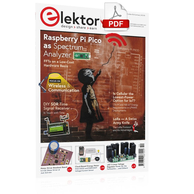
Elektor Digital Elektor September/October 2023 (PDF)
Elektor GREEN and GOLD members can download their digital edition here. Not a member yet? Click here. Raspberry Pi Pico as Spectrum AnalyzerFFTs on a Low-Cost Hardware Basis ±40-V Linear Voltage RegulatorAn Alternative Power Supply for the Fortissimo-100 Power Amplifier… and Others! MCU Wireless Communication Made FlexibleEEPROM Opens Networking Prospects for Wireless MCUs €5,000 up for grabs!Join the STM32 Wireless Innovation Design Contest 2023: An AI OdysseyGetting Started with ChatGPT’s Code Interpreter LoRa, a Swiss Army Knife (1)The LoRa Protocol and Its Advantages Adjustable Current Sink with Integrated Clock GeneratorTest Power Supplies, Voltage Converters and Batteries Two New Arduino UNO R4 Boards: Minima and WiFi Logarithmic PotentiometersThey’re Exponential! Motor Driver Breakout BoardA BoB for a 5 A DC Motor Driver with a 3×3 mm Size From Life’s ExperienceHazardous Electronics Is Cellular the Lowest-Power Option for IoT?LTE-M and NB-IoT Energy Requirements in LPWAN Deployments Wireless Communication in IoT Systems – Using Arduino MKR ModulesThe Right Board for Wi-Fi, LoRa, and Many More Standards AC Losses in Magnetic ComponentsAvoid Hot Inductors! Measurement for Optimal Cloud Deployment Matter Adoption: What does it take to deploy Matter devices? YARD Stick OneA Sub-1 GHz Wireless Test Tool Latching RelaysPeculiar Parts, the Series PIC O’Clock – In Touch with TimeDesigning an SDR Time Signal Receiver Due Diligence DirectiveBusiness as Usual Will Not Do Starting Out in Electronics……Voltage Amplification Infrasound Recorder with the Arduino Pro MiniA Sample Project from Elektor’s “Arduino & Co.” Book Cloud-Based Energy MeterWith ESP32 Module and PZEM-004T Voltage/Current Sensor A Bare-Metal Programming Guide (Part 2)Accurate Timing, the UART, and Debugging Hexadoku
€ 7,50
-

Elektor Digital Building Wireless Sensor Networks with OpenThread (E-book)
Developing CoAP applications for Thread networks with Zephyr This book will guide you through the operation of Thread, the setup of a Thread network, and the creation of your own Zephyr-based OpenThread applications to use it. You’ll acquire knowledge on: The capture of network packets on Thread networks using Wireshark and the nRF Sniffer for 802.15.4. Network simulation with the OpenThread Network Simulator. Connecting a Thread network to a non-Thread network using a Thread Border Router. The basics of Thread networking, including device roles and types, as well as the diverse types of unicast and multicast IPv6 addresses used in a Thread network. The mechanisms behind network discovery, DNS queries, NAT64, and multicast addresses. The process of joining a Thread network using network commissioning. CoAP servers and clients and their OpenThread API. Service registration and discovery. Securing CoAP messages with DTLS, using a pre-shared key or X.509 certificates. Investigating and optimizing a Thread device’s power consumption. Once you‘ve set up a Thread network with some devices and tried connecting and disconnecting them, you’ll have gained a good insight into the functionality of a Thread network, including its self-healing capabilities. After you’ve experimented with all code examples in this book, you’ll also have gained useful programming experience using the OpenThread API and CoAP.
€ 32,95
Members: € 29,66
-

Elektor Digital SDR Hands-on Book (E-book)
The short-wave technique has a very particular appeal: It can easily bridge long distances. By reflecting short-wave signals off the conductive layers of the ionosphere, they can be received in places beyond the horizon and therefore can reach anywhere on earth. Although technology is striving for ever higher frequencies, and radio is usually listened to on FM, DAB+, satellite or the Internet, modern means of transmission require extensive infrastructure and are extremely vulnerable. In the event of a global power outage, there is nothing more important than the short-wave. Amateur radio is not only a hobby, it’s also an emergency radio system! Elektor’s SDR-Shield is a versatile shortwave receiver up to 30 MHz. Using an Arduino and the appropriate software, radio stations, morse signals, SSB stations, and digital signals can be received. In this book, successful author and enthusiastic radio amateur, Burkhard Kainka describes the modern practice of software defined radio using the Elektor SDR Shield. He not only imparts a theoretical background but also explains numerous open source software tools.
€ 29,95
Members: € 26,96
-

Elektor Digital Elektor 07-08/2026 (PDF) DE
Diese Ausgabe steht allen GOLD- und GREEN-Mitgliedern auf der ElektorMagazine-Website zum Download bereit! Sie sind noch kein Mitglied? Hier klicken! MultiRF-EntwicklungsboardEine Plattform zur Evaluierung drahtloser Protokolle für kurze und lange Reichweiten Elektor wird 65Elektronik im Wandel seit 1961 WLAN-basierte Personenerkennung mit dem ESP32Wenn der Router zum Bewegungsmelder wird Drahtlose WaagenVier kleine Waagen = eine große Waage Walter, das kompakte IoT-ModulESP32-S3-SoC, LTE-M/NB-IoT-5G-Modem und GNSS-Receiver 3- und 4-Draht-RTD-Sensoren konditionierenMit Vollbereichsabgleich und Kabelkompensation Drei in einem: 2-Kanal-Oszilloskop/Generator/MultimeterEin Test des Fnirsi 2D15P electronica Fast Forward 2026 für Start-ups und Industriepartner EcologgingEine modulare IoT-Messstation für Umweltdaten Drahtlos-Anbindung für MedizingeräteImmer am Puls mit Bluetooth LE AudiotronicsBrummunterdrückung Mehr Effizienz in der Landwirtschaft durch KI-Modelle und SensorenSteigerung der landwirtschaftlichen Produktivität OPC UA – ein ÜberblickPlattformunabhängiger Datenaustausch Redox-Meter Instrumentenverstärker für Physik- und Engineering-Experimente Aktive differentielle Audio-FilterFür professionelle Frequenzweichen und mehr Elektor-Community-Tipps zu IoT und Sensoren Telegram-gesteuerter WarmwasserbereiterEine Lösung mit ESP32 und Arduino-Software 2026: Eine KI-OdysseeWas wurde eigentlich aus der Fuzzy-Logik? Projekt 2.0 Alarmsignalinjektor + PowerTools zum Suchen verdeckt verlegter Leitungen
€ 11,90
-
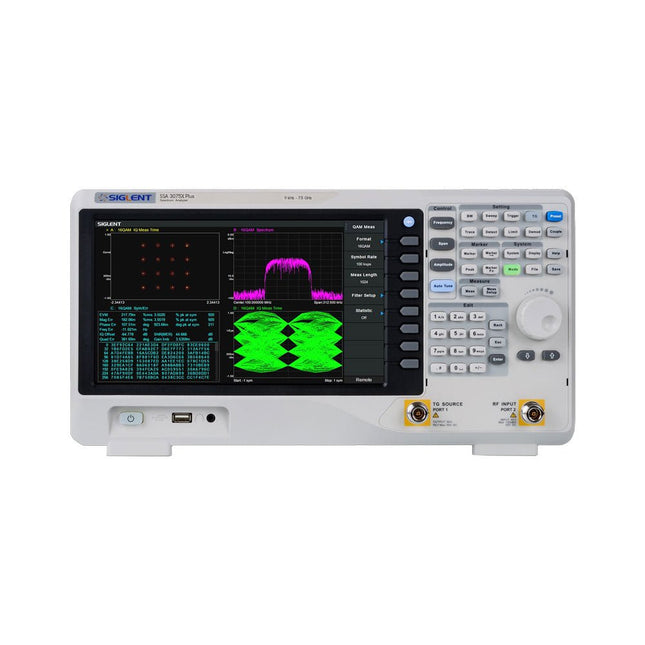
Siglent Siglent SSA3075X Plus Spectrum Analyzer (9 kHz – 7.5 GHz)
The Siglent SSA3075X Plus spectrum analyzer is a powerful and flexible tool for RF signal and network analysis. With a frequency range of 7.5 GHz, the analyzer delivers reliable automatic measurements and multiple modes of operation: spectrum analyzer the base, optional functions include RF power measurement, vector signal modulation analysis, reflection measurement, and EMI test. Applications include broadcast monitoring/evaluation, site surveying, S-parameter measurement, analog/digital modulation analysis, EMI pre-compliance test, research and development, education, production, and maintenance. Features Spectrum Analyzer Frequency Range from 9 kHz to 7.5 GHz –165 dBm/Hz Displayed Average Noise Level (Typ.) –98 dBc/Hz. @ 10 kHz Offset Phase Noise (1 GHz, Typ.) Level Measurement Uncertainty <0.7 dB (Typ.) 1 Hz Minimum Resolution Bandwidth (RBW) Preamplifier (Std.) Tracking Generator (incl. free of charge) Analog and Digital Signal Modulation Analysis Mode (opt.) Reflection Measurement Kit (opt.) EMI Filter and Quasi-Peak Detector Kit (opt.) Advanced Measurement Kit (opt.) 10.1-inch Multi-Touch Screen , Mouse and Keyboard supported Web Browser Remote Control on PC and Mobile Terminals and File Operation Specifications SSA3015X Plus SSA3021X Plus SSA3032X Plus SSA3075X Plus Frequency Range 9 kHz ~ 1.5 GHz 9 kHz ~ 2.1 GHz 9 kHz ~ 3.2 GHz 9 kHz ~ 7.5 GHz Resolution Bandwidth 1 Hz ~ 1 MHz 1 Hz ~ 1 MHz 1 Hz ~ 1 MHz 1 Hz ~ 3 MHz Phase Noise <–99 dBc/Hz <–98 dBc/Hz <–98 dBc/Hz <–98 dBc/Hz Total Amplitude Accuracy <1.2 dB <0.7 dB <0.7 dB <0.7 dB Display Average Noise Level –156 dBm/Hz –161 dBm/Hz –161 dBm/Hz –165 dBm/Hz Included Siglent SSA3075X Plus spectrum analyzer USB cable Power cord Quick start guide Downloads Datasheet Manual Documentation Firmware
€ 7.875,89
-
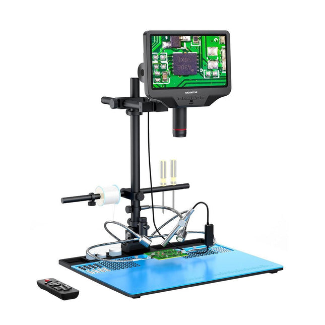
Andonstar Andonstar AD409 Max-ES 10.1" HDMI Digital Microscope (incl. Endoscope)
The Andonstar AD409 Max-ES boosts a high-quality metal lens and a unique UV filter design. Crafted from top-tier industrial-grade materials, it delivers unmatched precision and durability, ensuring a reliable product experience. The UV filter positioned in front of the metal lens blocks soldering heat, smoke, and dust, safeguarding the lens and making it perfect for soldering and maintenance professionals. The AD409 Max-ES features an oversized Max station (46 x 37 x 47.5 cm) and an advanced tool set, expanding the soldering station area by 370%. This upgrade meets the demands of professional soldering tasks and provides ample workspace for larger projects. The easy-to-use tool holder keeps tools within reach, ensuring they are always accessible. Additionally, the soldering helping hands with rotatable clamps simplify soldering and repair tasks, enhancing efficiency and convenience. The endoscope offers an all-around 360° view. This allows for clear observation of components from all sides and inside pipes, eliminating blind spots and ensuring thorough inspections. Features High-quality Metal Lens and Unique UV Filter Design New Max station Easy-to-use Tool Holder and Soldering Helping Hands Microscope with Endoscope All-around View 360° Professional HDMI Digital Microscope supports Multiple Output Methods 8 Levels adjustable LEDs Convenient Wireless Remote Control Specifications Screen size 10.1 inch (1280x800) Image sensor 4 MP Video output UHD 2880x2160 (24fps)FHD 1920x1080 (60fps/30fps)HD 1280x720 (120fps) Video format MP4 Magnification Up to 300 times (27 inch HDMI monitor) Photo resolution Max. 24 MP (5600x4200) Photo format JPG Focus range Min. 5 cm Frame Rate Max. 120fps Video interface HDMI Storage microSD card (up to 64 GB) PC support Windows, PC software with measurement Mobile phone, tablet terminal support Support WiFi connection and measurement Power source 5 V DC Light source 2 LEDs with the stand Endoscope Yes Stand size 46 x 37 x 47.5 cm (18.1 x 14.6 x 18.7") Included 1x Andonstar AD409 Max-ES Digital Microscope 1x Endoscope 1x Stand with 2 LEDs 1x UV filter (already assembled in the lens) 1x Soldering mat 1x Beam 1x Column 1x Tool holder 1x Soldering Helping Hands 1x Power adapter 1x Power cable 1x HDMI cable 1x USB cable 1x IR remote 1x Manual Downloads Manual Software
€ 399,00€ 339,00Best Price
-

OWON OWON SPS3081 Fanless DC Power Supply (120 W)
The OWON SPS3081 Fanless Programmable DC Power Supply (120 W) delivers ultra-quiet, high-precision performance with 10 mV/1 mA accuracy and advanced heat dissipation for long-term reliability. Featuring comprehensive protection, a USB interface with SCPI support for remote control, and a 2.8-inch TFT LCD screen, it is the perfect choice for laboratories, electronics testing, and research. Features Fanless design: Ultra-quiet operation, reducing vibration noise and minimizing the potential failure risks associated with traditional cooling fans. Excellent heat dissipation design: Ensures a controlled temperature rise, allowing long-term operation under full load conditions and extending internal component longevity. Lightweight and ultra-thin design. Output accuracy up to 10 mV/1 mA. Supports List waveform editing and output, with four memory shortcut parameters for quick and convenient access. Integrated protection features include overvoltage, overcurrent, overtemperature, and input undervoltage protection for enhanced safety. Built-in discharge circuit prevents residual high voltage risks when the power is turned off. USB communication interface with SCPI protocol support, enabling PC programming and remote control for simplified user management. 2.8-inch TFT LCD screen Specifications Model SPS6051 SPS3081 Rated Output (0°C-40°C) Voltage 0-61 V 0-31 V Current 0-5.1 A 0-8.1 A Power 150 W 120 W Load Regulation Voltage ≤30 mV Current ≤20 mA Power Regulation Voltage ≤30 mV Current ≤20 mA Setting Resolution Voltage 10 mV Current 1 mA Readback Resolution Voltage 10 mV Current 1 mA Seting Accuracy (25°C ±5°C) Voltage ≤0.05% ±20 mV ≤0.1% ±20 mV Current ≤0.05% ±20 mA ≤0.2% ±20 mA Readback Accuracy (25°C ±5°C) Current ≤0.05% ±20 mV ≤0.1% ±20 mV Voltage ≤0.05% ±20 mV ≤0.2% ±20 mA Ripple/Noise Voltage ≤30 mVp-p ≤30 mVp-p Voltage ≤4 mVrms ≤5 mVrms Current ≤10 mAp-p ≤30 mAp-p Output temperature coefficient (0°C-40°C) Voltage 100 ppm/°C Current 200 ppm/°C Readback temperature coefficient Voltage 100 ppm/°C Current 200 ppm/°C Response Time (50-100% rated load) ≤1.0 ms Storage 4 groups of data Working Temperature 0-40°C Display 2.8-inch color LCD display Interface USB Dimensions (W x H x D) 82 x 142 x 226 mm Weight 1.8 kg Included 1x OWON SPS3081 Power Supply 2x Test leads 1x Power cord 1x Manual Downloads Datasheet User Manual Programming Manual PC Software
€ 137,94
-

Seeed Studio Seeed Studio RF Explorer 3G Combo Spectrum Analyzer
The Seeed Studio RF Explorer 3G Combo is a handheld digital spectrum analyzer and an affordable tool for working across a wide range of popular frequency bands. It is based on a highly integrated frequency synthesizer and a double-balanced mixer, providing high performance, compact dimensions, low power consumption, and excellent value. Designed for both indoor and outdoor use, the RF Explorer 3G Combo can also be connected to a PC via a standard Mini-USB 2.0 connector for additional functionality. This model combines a WSUB1G base unit with an RFEMWSUB3G expansion module, supplied fully assembled and tested. It features two SMA connectors and includes two antennas: a dual-band 144/430 MHz telescopic antenna for sub-GHz frequencies and a helical whip antenna for the 2.4 GHz band. Additional frequency-specific antennas may be required for optimal performance in certain supported frequency ranges. This combination provides the wide frequency coverage of the WSUB3G module together with the high sensitivity and fast response of the WSUB1G unit in the commonly used sub-1 GHz frequency range. Features Pocket size and light weight Solid aluminum metal case Includes a transport EVA carry case for RF Explorer Spectrum Analyzer mode with Peak Max and Hold, Normal, Overwrite and Averaging modes Lifetime free firmware upgrades available, open to community requested features High capacity Lipo for 16+ hours of continuous run, rechargeable by USB Windows PC client Open Source Can be extended with internal Expansion Modules for additional band and functionality Wide band coverage to all popular RF frequencies, starting at 15 MHz and going up to 2.7 GHz. This includes very interesting frequency areas such as 2 m HAM radio, all VHF and UHF, FM radio, GPS, WiFi and WiMax, Bluetooth, etc. Firmware: RF Explorer 3G Combo is delivered with upgraded firmware v1.09. Note some of the features and operation accuracy will be improved in upcoming free firmware revisions. Specifications Battery Lithium Cells / Batteries contained in equipment UN3481 - PI967 Frequency band 15-2700 MHz Frequency span 112 KHz - 600 MHz Graphics LCD 128 x 64 pixels, great visibility outdoors PC Windows client Supports Windows (32 and 64 bits) Backlight For great indoor visibility 2 standard SMA 50 ohms connector, One for Sub-GHz wideband Nagoya NA-773 telescopic antenna included and another 2.4 GHz one for 15-2700 MHz band with helical antenna included. Amplitude resolution 0.5 dBm Dynamic range Left SMA port (WSUB1G) -115 dBm to 0 dBm Right SMA port (WSUB3G) -110 dBm to -10 dBm Absolute Max input power Left SMA port (WSUB1G) +5 dBm Right SMA port (WSUB3G) +30 dBm Average noise level (typical) -110 dBm Frequency stability and accuracy (typical) ±10 ppm Amplitude stability and accuracy (typical) ±6 dBm Frequency resolution 1 KHz Resolution bandwidth (RBW) Automatic 3 KHz to 600 KHz Weight 185 g Dimensions 113 x 70 x 25 mm Included Seeed Studio RF Explorer 3G Combo Spectrum Analyzer Nagoya NA-773 wideband telescopic antenna 2.4 GHz band antenna EVA Case Documentation For more info and to get started with your RF Explorer, visit the start page. For questions and support, please visit https://support.rf-explorer.com
€ 279,95
-

Holybro Holybro X500 V2 ARF Drone Kit
The X500 V2 ARF Kit is an affordable, lightweight, and robust carbon fiber professional drone kit that is easy to assemble (less than 15 minutes). It comes with the X500 V2 Frame Kit and motors, ESCs, power distribution boards and propellers preinstalled. It is perfectly compatible with various flight controllers such as the Holybro Pixhawk series, Durandal, Pix32 V5, etc. There are numerous improvements compared the previous model. Specifications Wheelbase: 500 mm Motor mount pattern: 16x16 mm Frame body: 144x144 mm, 2 mm thick Landing gear height: 215 mm Space between top and bottom plates: 28 mm Weight: 610 g Flight time: ~18 minutes hover with no additional payload. Tested with 5000 mAh battery. Payload: 1500 g (without battery, 70% throttle) Battery recommendation: 4S 3000-5000 mAh 20C+ with XT60 Lipo battery (not Included) Included X500 V2 Frame Kit With Preinstalled Items: 4x Motors: Holybro 2216 KV920 Motor (4 pcs) with XT30 Plug 4x ESCs (BLHeli S ESC 20A) 6x 1045 Propellers Power Distribution Board – XT60 plug for battery & XT30 plug for ESCs & peripherals Note: Depth camera mount is sold separately.
€ 379,95
Best Price


