
Search results for "mastering or microcontrollers or helped or by or arduino or 6451"
-

Elektor Digital CAN et CAN FD (E-book)
Tout sur les protocoles et leur mise en œuvre avec Arduino Initialement destiné aux véhicules routiers, le réseau CAN (« Controller Area Network ») et son successeur le réseau CAN FD (« Flexible Data ») ont vu leurs champs d’application s’élargir à de nouveaux domaines. L’industrie propose de nombreux modules microcontrôleurs dotés d’une interface CAN et/ou CAN FD. L’environnement de développement Arduino a démocratisé la programmation de ces modules et il existe des bibliothèques qui implémentent un pilote CAN et/ou un pilote CAN FD. La première partie dresse un rapide historique des réseaux CAN et CAN FD et expose la problématique des lignes de transmission en abordant succinctement leur théorie et présentant des résultats de simulation Spice. La deuxième partie est consacrée au réseau CAN, en détaillant successivement la fonction logique du réseau, les transcepteurs, les contrôleurs, la topologie la plus classique (le bus) et d’autres moins courantes, les répéteurs et les passerelles. Les aspects particuliers du protocole, tels que le bit stuffing, l’arbitrage, les trames d’erreur, la détection des erreurs sont exposés. La discussion de la fiabilité du protocole est illustrée par des exemples mettant en évidence ses faiblesses. La troisième partie présente le protocole CAN FD, ses deux variantes CAN FD ISO et CAN FD non ISO, leurs fiabilités, leurs faiblesses, mises en évidence par des exemples. Différents transcepteurs et contrôleurs CAN FD sont décrits. La quatrième partie est dédiée aux applications : comment utiliser les services d’un pilote, concevoir une messagerie, utiliser un analyseur logique. Deux exemples d’application terminent cette partie. Ce livre s’adresse aux amateurs et aux ingénieurs non spécialistes pour comprendre les possibilités qu’offre un réseau CAN et comment on le met en œuvre. Un enseignant trouvera des informations pour approfondir ses connaissances et pour concevoir des travaux pratiques. Une connaissance des microcontrôleurs, de leur programmation, de l’électronique numérique aidera à la lecture des schémas. La connaissance du langage C++ et du langage de simulation électronique Spice facilitera la compréhension des programmes qui sont décrits dans le livre. Tous les codes source sont disponibles sur le dépôt GitHub de l’auteur. Téléchargements GitHub
€ 34,95
Members: € 31,46
-
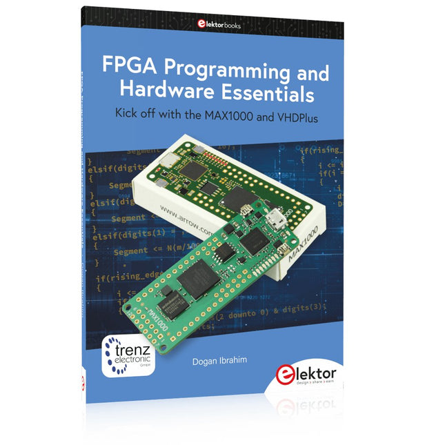
Elektor Publishing FPGA Programming and Hardware Essentials
Kick off with the MAX1000 and VHDPlus Ready to Master FPGA Programming? In this guide, we’re diving into the world of Field Programmable Gate Arrays (FPGAs) – a configurable integrated circuit that can be programmed after manufacturing. Imagine bringing your ideas to life, from simple projects to complete microcontroller systems! Meet the MAX1000: a compact and budget-friendly FPGA development board packed with features like memory, user LEDs, push-buttons, and flexible I/O ports. It’s the ideal starting point for anyone wanting to learn about FPGAs and Hardware Description Languages (HDLs). In this book, you’ll get hands-on with the VHDPlus programming language – a simpler version of VHDL. We’ll work on practical projects using the MAX1000, helping you gain the skills and confidence to unleash your creativity. Get ready for an exciting journey! You’ll explore a variety of projects that highlight the true power of FPGAs. Let’s turn your ideas into reality and embark on your FPGA adventure – your journey starts now! Exciting Projects You’ll Find in This Book Arduino-Driven BCD to 7-Segment Display Decoder Use an Arduino Uno R4 to supply BCD data to the decoder, counting from 0 to 9 with a one-second delay Multiplexed 4-Digit Event Counter Create an event counter that displays the total count on a 4-digit display, incrementing with each button press PWM Waveform with Fixed Duty Cycle Generate a PWM waveform at 1 kHz with a fixed duty cycle of 50% Ultrasonic Distance Measurement Measure distances using an ultrasonic sensor, displaying the results on a 4-digit 7-segment LED Electronic Lock Build a simple electronic lock using combinational logic gates with push buttons and an LED output Temperature Sensor Monitor ambient temperature with a TMP36 sensor and display the readings on a 7-segment LED Downloads Software
€ 39,95
Members: € 35,96
-

Elektor Digital MIT App Inventor Projects (E-book)
50+ Android Apps with Raspberry Pi, ESP32 and Arduino This book is about developing apps for Android compatible mobile devices using the MIT App Inventor online development environment. MIT App Inventor projects can be in either standalone mode or use an external processor. In standalone mode, the developed application runs only on the mobile device (e.g. Android). In external processor-based applications, the mobile device communicates with an external microcontroller-based processor, such as Raspberry Pi, Arduino, ESP8266, ESP32, etc. In this book, many tested and fully working projects are given both in standalone mode and using an external processor. Full design steps, block programs, circuit diagrams, QR codes and full program listings are given for all projects. The projects developed in this book include: Using the text-to-speech component Intonating a received SMS message Sending SMS messages Making telephone calls using a contacts list Using the GPS and Pin-pointing our location on a map Speech recognition and speech translation to another language Controlling multiple relays by speech commands Projects for the Raspberry Pi, ESP32 and Arduino using Bluetooth and Wi-Fi MIT APP Inventor and Node-RED projects for the Raspberry Pi The book is unique in that it is currently the only book that teaches how to develop projects using Wi-Fi and Node-RED with MIT App Inventor. The book is aimed at students, hobbyists, and anyone interested in developing apps for mobile devices. All projects presented in this book have been developed using the MIT App Inventor visual programming language. There is no need to write any text-based programs. All projects are compatible with Android-based mobile devices. Full program listings for all projects as well as detailed program descriptions are given in the book. Users should be able to use the projects as they are presented, modifying them to suit their own needs.
€ 32,95
Members: € 29,66
-

Elektor Digital Elektor March/April 2024 (PDF)
Elektor GREEN and GOLD members can download their digital edition here. Not a member yet? Click here. CaptureCountAn Object Detector and Counter on the Raspberry Pi 5 Voltage Reference With Arduino Pro MiniLinearize and Calibrate Your Analog Inputs FPGAs for BeginnersThe Path From MCU to FPGA Programming Update: STM32 Wireless Innovation Design Contest 2024 Bluetooth LE With MAUIControl Apps for Android & Co. Port-Expanding Breakout BoardIncrease the Number of I/Os on Your Dev Board AI SpecialistMachine Learning with the Jetson Nano 2024: An AI OdysseyFirst Forays Into TensorFlow 262,144 Ways to Play The Game of LifeA Reader’s Project in Brief From Life’s ExperienceThe Chinese Dragon Get Your (Brushed DC) Motor Running!Sample Projects from the Elektor Motor Control Development Bundle ESP32-RS-232 AdapterA Wireless Link for Classic Test Equipment Starting Out in Electronics……More About Opamps ESP Library Recommendations Piezoelectric DevicesPeculiar Parts, the Series A Smart Object CounterImage Recognition Made Easy with Edge Impulse Resolve Your Trickiest Embedded Development Challenges ESP32 TerminalA Handheld Device with a Touch-Capable Display Getting Started With the Zephyr RTOSAs Powerful as It Is Hard to Master Award-Winning EthicsA Dialog with CTO Alexander Gerfer of Würth Elektronik eiSos on Enabling Innovation and Mindful Behavior Err-lectronicsCorrections, Updates, and Readers’ Letters Infographics: Embedded and AI Square Wave Generation BenchmarksExploring ESP32, Pico, and Other Microcontrollers
€ 7,50
-

Elektor Bundles Mikrocontroller-Praxiskurs für Arduino-Einsteiger (Bundle)
Mit dem Elektor Arduino Nano Trainingsboard (MCCAB) eigene Projekte realisieren Der Mikrocontroller ist das wohl faszinierendste Teilgebiet der Elektronik, denn aufgrund der Vielzahl von Funktionen, die er auf seinem Chip vereinigt, ist er für den Entwickler ein universelles Multi-Tool zur Realisierung seiner Projekte. Praktisch jedes Gerät des täglichen Gebrauchs wird heute von einem Mikrocontroller gesteuert. Für einen elektronischen Laien blieb es aufgrund der Komplexität bisher allerdings ein Wunschtraum, eigene Ideen mit einem Mikrocontroller zu realisieren. Das Arduino-Konzept hat den Einsatz von Mikrocontrollern weitgehend vereinfacht, sodass jetzt auch Laien eigene Elektronik-Ideen mit einem Mikrocontroller verwirklichen können. Buch & Hardware im Bundle: 'Learning by Doing' Dieses im Bundle mitgelieferte Buch (im großen A4-Format) zeigt, wie man auch ohne große Erfahrung in Elektronik und Programmiersprachen eigene Projekte mit einem Mikrocontroller realisieren kann. Es ist ein Mikrocontroller-Praxiskurs für Einsteiger, denn nach einem Überblick über die Interna des Mikrocontrollers und einer Einführung in die Programmiersprache C liegt der Schwerpunkt des Kurses auf den praktischen Übungen. Der Leser eignet sich die erforderlichen Kenntnisse durch 'Learning by Doing' an: in dem umfangreichen Praxisteil mit 12 Projekten und 46 Übungen wird das im vorderen Teil des Buches Gelernte mit vielen Beispielen unterlegt. Die Übungen sind dabei so aufgebaut, dass der Bearbeiter eine Aufgabenstellung erhält, die er mit seinem im Theorieteil des Buches aufgebauten Wissen löst. Für jede Übung gibt es anschließend eine ausführlich erklärte und kommentierte Musterlösung, die dem Bearbeiter bei Problemen weiterhilft und die er mit seiner eigenen Lösung vergleichen kann. Arduino IDE In der Arduino IDE, einer Software-Entwicklungsumgebung, die kostenlos auf den eigenen PC heruntergeladen werden kann und die das gesamte Softwarepaket enthält, das für ein eigenes Mikrocontroller-Projekt benötigt wird, schreibt der Bearbeiter mit dem Editor der IDE seine Programme („Apps“) in der Programmiersprache C. Der in die Arduino IDE integrierte Compiler übersetzt sie in die Bits und Bytes, die der Mikrocontroller versteht und die dann über ein USB-Kabel in den Speicher des Mikrocontrollers auf dem Elektor Arduino Nano Trainingsboard (MCCAB) geladen werden. Externe Sensoren, Motoren oder Baugruppen abfragen oder steuern Das Elektor Arduino Nano Trainingsboard (MCCAB) enthält neben einem Mikrocontrollermodul Arduino Nano alle für die Übungen benötigten Bauteile wie Leuchtdioden, Schalter, Taster, akustische Signalgeber usw. Auch externe Sensoren, Motoren oder Baugruppen können mit diesem Mikrocontroller-Übungssystem abgefragt oder gesteuert werden. Technische Daten (Arduino Nano Trainingsboard MCCAB) Stromversorgung Über die USB-Verbindung des zur Erstellung der Programme sowieso angeschlossenen PCs oder ein externes Netzteil (nicht im Lieferumfang enthalten) Betriebsspannung +5 Vcc Eingangsspannung Alle Eingänge 0 V bis +5 V VX1 und VX2 +8 V bis +12 V (nur bei Verwendung eines externen Netzteils) Mikrocontrollermodul Arduino Nano Hardwareperipherie LCD 2x16 Zeichen Potenziometer P1 & P2 JP3: Auswahl der Betriebsspannung von P1 & P2 Verteiler SV4: Verteiler für die BetriebsspannungenSV5, SV6: Verteiler für die Ein-/Ausgänge des Mikrocontrollers Schalter und Taster RESET-Taster auf dem Arduino Nano-Modul6x Tastschalter K1 … K66x Schiebeschalter S1 … S6JP2: Verbindung der Schalter mit den Eingängen des Mikrocontrollers Summer Piezo-Summer Buzzer1 mit Steckbrücke auf JP6 Leuchtanzeigen LED L auf dem Arduino Nano-Modul, verbunden mit GPIO D1311x LED: Zustandsanzeige für die Ein-/AusgängeJP6: Verbindung der LEDs LD10 … LD20 mit den GPIOs D2 … D12 Serielle SchnittstellenSPI & I²C JP4: Auswahl des Signals an Pin X der SPI-Steckerleiste SV12SV9 bis SV12: SPI-Interface (3,3 V/5 V) bzw. I²C-Interface Schaltausgang für externe Geräte SV1, SV7: Schaltausgang (maximal +24 V/160 mA, extern zugeführt)SV2: 2x13 Pins zum Anschluss externer Module 3x3 LED-Matrix (9 rote LEDs) SV3: Spalten der 3x3 LED-Matrix (Ausgänge D6 … D8)JP1: Verbindung der Reihen mit den GPIOs D3 … D5 Software Library MCCABLib Steuerung der Hardware-Komponenten (Schalter, Taster, Leuchtdioden, 3x3 LED-Matrix, Summer) auf dem MCCAB Trainingsboard Betriebstemperatur bis +40 °C Abmessungen 100 x 100 x 20 mm Technische Daten (Arduino Nano) Mikrocontroller ATmega328P Architektur AVR Betriebsspannung 5 V Flashspeicher 32 KB, davon 2 KB vom Bootloader belegt SRAM 2 KB Taktfrequenz 16 MHz Analoge IN-Pins 8 EEPROM 1 KB DC-Strom pro I/O-Pin 40 mA an einem I/O-Pin, insgesamt maximal 200 mA an allen Pins gemeinsam Eingangsspannung 7-12 V Digitale I/O-Pins 22 (6 davon sind PWM-fähig) PWM-Ausgänge 6 Stromverbrauch 19 mA Abmessungen 18 x 45 mm Gewicht 7 g Lieferumfang Elektor Arduino Nano MCCAB Trainingsboard Arduino Nano Buch: Mikrocontroller-Praxiskurs für Arduino-Einsteiger
-
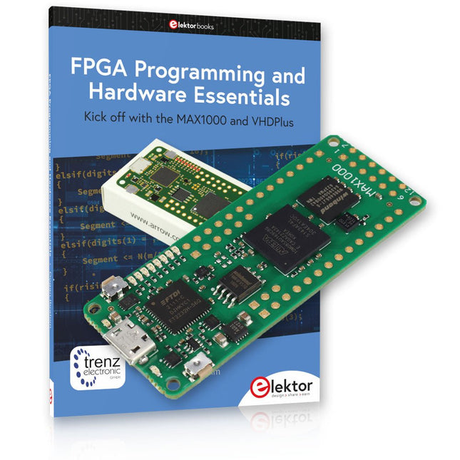
Elektor Bundles MAX1000 FPGA Programming Bundle
Kick off to FPGA Programming with the MAX1000 Board and VHDPlus Ready to master FPGA programming? With this bundle, you'll dive into the world of Field-Programmable Gate Arrays (FPGAs) – a configurable integrated circuit that can be programmed after manufacturing. Bring your ideas to life, from simple projects to complete microcontroller systems! The MAX1000 is a compact and powerful FPGA development board packed with features like memory, user LEDs, push-buttons, and flexible I/O ports. It’s the ideal starting point for anyone wanting to learn about FPGAs and Hardware Description Languages (HDLs). With the enclosed book "FPGA Programming and Hardware Essentials" you'll get hands-on with the VHDPlus programming language – a simpler version of VHDL. You'll work on practical projects using the MAX1000, helping you gain the skills and confidence to unleash your creativity. Projects in the Book Arduino-driven BCD to 7-Segment Display Decoder Use an Arduino Uno R4 to supply BCD data to the decoder, counting from 0 to 9 with a one-second delay Multiplexed 4-Digit Event Counter Create an event counter that displays the total count on a 4-digit display, incrementing with each button press PWM Waveform with Fixed Duty Cycle Generate a PWM waveform at 1 kHz with a fixed duty cycle of 50% Ultrasonic Distance Measurement Measure distances using an ultrasonic sensor, displaying the results on a 4-digit 7-segment LED Electronic Lock Build a simple electronic lock using combinational logic gates with push buttons and an LED output Temperature Sensor Monitor ambient temperature with a TMP36 sensor and display the readings on a 7-segment LED MAX1000 FPGA Development Board The MAX1000 is a customizable IoT/Maker Board ready for evaluation, development and/or use in a product. It is built around the Intel MAX10 FPGA, which is the industry’s first single chip, non-volatile programmable logic device (PLDs) to integrate the optimal set of system components. Users can now leverage the power of tremendous re-configurability paired with a high-performance, low-power FPGA system. Providing internally stored dual images with self-configuration, comprehensive design protection features, integrated ADCs and hardware to implement the Nios II 32-bit microcontroller IP, MAX10 devices are ideal solution for system management, protocol bridging, communication control planes, industrial, automotive and consumer applications. The MAX1000 is equipped with an Arrow USB Programmer2, SDRAM, flash memory, accelerometer sensor and PMOD/Arduino MKR connectors making it a fully featured plug and play solution without any additional costs. Specifications MAX 10 8 kLE - Flash Dual inside - ADC 8x 12 Bit - Temperature Range 0~85°C - Supply USB/pins SDRAM 8 MB 3-axis MEMS LIS3DH USB Programmer on board MEMS Oscillator 12 MHz Switch/LED 2x / 8x Contents of the Bundle Book: FPGA Programming and Hardware Essentials (normal price: €40) MAX1000 FPGA Development Board (normal price: €45) Downloads Software
-

NXP Semiconductors NXP FRDM-MCXN947 Development Board
The FRDM-MCXN947 is a compact and versatile development board designed for rapid prototyping with MCX N94 and N54 microcontrollers. It features industry-standard headers for easy access to the MCU's I/Os, integrated open-standard serial interfaces, external flash memory, and an onboard MCU-Link debugger. Specifications Microcontroller MCX-N947 Dual Arm Cortex-M33 cores @ 150 MHz each with optimized performance efficiency, up to 2 MB dual-bank flash with optional full ECC RAM, External flash Accelerators: Neural Processing Unit, PowerQuad, Smart DMA, etc. Memory Expansion *DNP Micro SD card socket Connectivity Ethernet Phy and connector HS USB-C connectors SPI/I²C/UART connector (PMOD/mikroBUS, DNP) WiFi connector (PMOD/mikroBUS, DNP) CAN-FD transceiver Debug On-board MCU-Link debugger with CMSIS-DAP JTAG/SWD connector Sensor P3T1755 I³C/I²C Temp Sensor, Touch Pad Expansion Options Arduino Header (with FRDM expansion rows) FRDM Header FlexIO/LCD Header SmartDMA/Camera Header Pmod *DNP mikroBUS User Interface RGB user LED, plus Reset, ISP, Wakeup buttons Included 1x FRDM-MCXN947 Development Board 1x USB-C Cable 1x Quick Start Guide Downloads Datasheet Block diagram
-
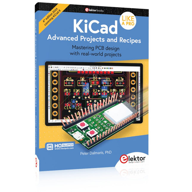
Elektor Publishing KiCad Like A Pro – Advanced Projects and Recipes
Mastering PCB design with real-world projects This book builts on KiCad Like a Pro – Fundamentals and Projects and aims to help you practice your new KiCad skills by challenging you in a series of real-world projects. The projects are supported by a comprehensive set of recipes with detailed instructions on how to achieve a variety of simple and complex tasks. Design the PCBs for a solar power supply, an LED matrix array, an Arduino-powered datalogger, and a custom ESP32 board. Understand the finer details of the interactive router, how to manage KiCad project teams with Git, how to use an autorouter on 2 and 4-layer PCBs, and much more. KiCad 8 is a modern, cross-platform application suite built around schematic and design editors. This stable and mature PCB tool is a perfect fit for electronic engineers and makers. With KiCad 8, you can create PCBs of any complexity and size without the constraints associated with the commercial packages. Here are the most significant improvements and features in KiCad 8, both over and under the hood: Modern user interface, completely redesigned from earlier versions Improved and customizable electrical and design rule checkers Theme editor allowing you to fully customize the look of KiCad on your screen Ability to import projects from Eagle, CADSTART, and more An improved and tightly integrated SPICE circuit simulator Autorouting with the Freerouting plugin Filters define which elements of a layout are selectable Enhanced interactive router helps you draw single tracks and differential pairs with precision New or enhanced tools to draw tracks, measure distances, tune track lengths, etc. Enhanced tool for creating filled zones A customizable coordinate system facilitates data exchange with other CAD applications Realistic ray-tracing capable 3D viewer Differential pair routing Rich repositories of symbol, footprint, and 3D shape libraries Python scripting API for programmatic customization and extensions Improved footprint wizard for fast custom footprints


