
Search results for "ersa OR i OR con OR pico OR soldering OR station OR 80 OR w"
-
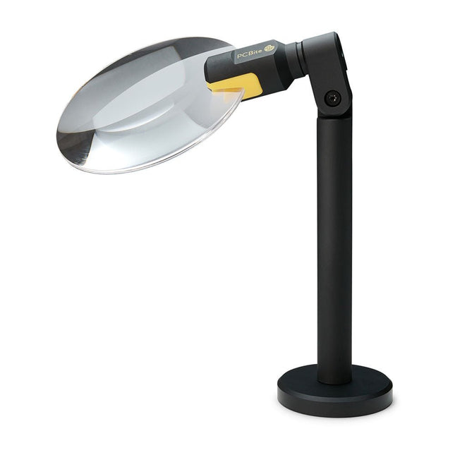
Sensepeek Sensepeek 4020 PCBite 3x Magnifier
The PCBite Magnifier (premium build quality made from CNC machined aluminum) enlarges your target and makes it easier to see during soldering, inspection and measurements. Especially useful when placing PCBite hands free probes on fine pitch SMD components during measurements. 3x magnification edgeless lens for increased visibility of the work surface and AR coating (anti-reflection) to reduce reflections from nearby light sources. Optimized design, magnification and focal point for use together with the PCBite PCB holders and baseplates included in all PCBite kits. Can also be used handheld but not standalone without a metal surface as base. At the bottom of the magnifier foot there is a strong magnet perfectly balanced in strength. A low friction bottom cap protects the magnet and the baseplate to make the magnifier easy to slide when repositioning or removing the magnifier from the baseplate. Friction based adjustment of lens tilt and rotate positions takes away the need for annoying and complicated set screws.
€ 71,39
-

Elektor Digital Elektor 03-04/2026 (PDF) DE
Diese Ausgabe steht allen GOLD- und GREEN-Mitgliedern auf der ElektorMagazine-Website zum Download bereit! Sie sind noch kein Mitglied? Hier klicken! PIO-Programmierung des Raspberry Pi PicoNeun Befehle, viele Möglichkeiten KI aus dem Browser befreienSo nutzen Sie KI-CLIs zum Programmieren, Kompilieren und Validieren von Embedded-Projekten Der Scrutiny DebuggerDebuggen, Visualisieren und Testen von Embedded-C/C++ Code Sigfox-Breakout-Board (Teil 1)Ein selbst gebautes Funk-BoB Rauscharmes Labor-Netzteil (Teil 2)Konstruktion, Montage und praktische Implementierung Einfacher Signalgenerator mit dem RP2040Analoge und digitale Signale für rund 10 Euro Matter und Edge-KI für die Smart Homes der ZukunftBieten die neuesten Updates von Matter und der Aufstieg der Edge-KI Entwicklern endlich die Werkzeuge, um das versprochene intelligente und vernetzte Smart Home zu schaffen? Die SMU für alleSiglent bringt die SMM3000X-Serie auf den Markt DifferenzdrucksensorenVorausschauende Wartung in HLK-Systemen Security by DesignSchadensbegrenzung durch Entwicklungsprinzipien Embedded Security ist nicht mehr optional CRA und PQC setzen neue Prioritäten für Embedded-SicherheitWarum auch kleine IoT- und Industrie-Unternehmen einen Upgrade-Plan benötigen embedded world 2026Interview mit Benedikt Weyerer, Executive Director der embedded world I3C in der PraxisMit Hardware von ST und Microchip Das BLEnky-ProjektSchnelles Prototyping für Bluetooth-Low-Energy-Anwendungen PulsbreitensteuerungVom einfachen Thermostat bis zum geglätteten Analogsignal AudiotronicsKlangvolle Elektronik zum Selberbauen ESP32-Audio-Transceiver-Board (Teil 4)Taktsynchronisation – und eine kabelgebundene Option 2026: Eine KI-OdysseeDer Vibe-Coding-Kater von 2025 Symmetrische DC-LastGleichstromlast, statisch oder dynamisch und symmetrisch Gesichter zählen mit MaixCAMEine einfache Methode zur Erfassung von Publikumsgrößen
€ 11,90
-

Elektor Digital Elektor November/December 2022 PDF (NL)
Elektor GREEN en GOLD leden kunnen deze uitgave hier downloaden.Nog geen lid? Klik hier om een lidmaatschap af te sluiten. High-end uit het Elektor-lab Fortissimo-100 high-end versterkervolledig symmetrische audio-eindtrap levert 100/190 W Controleer de frequentie van afgestemde kringen en kristallen Printen ontwerpentips en trucs Solderen – nou en?moderne soldeertechnologie nader bekeken Bluetooth-garagedeurbediening met geringe latentiemet korte BLE-berichten vanaf een smartphone Ideale diode-controllerdiodeschakelingen met geringe vermogensdissipatie LED-slingers met ESP32 en FreeRTOSknipperen dat het een lieve lust is Alle begin......zenert er vrolijk op los FM/DAB+ ontvangerhet beste van twee werelden Uit het leven gegrepenelektronica obscura De oorzaak van software-bugs draadloos opsporencirculaire buffer en webserver op de ESP32 Heeft Covid de innovatie gestimuleerd?innovatieve componenten en oplossingen uit 2022 Ersa i-CON TRACEhet IoT-soldeerstation voor makers Elektor Infographics Wat moeten we met al die computers? Aansturing van het e-paper display van Ynvisible InnoFaith: innovatie en nog eens innovatievraaggesprek met Walter Arkesteijn Industriële automatiseringeenvoudige en schaalbare IoT-retrofitting Reed-relaisvreemde onderdelen Low-profile lineaire connectorenvereenvoudigen multisignaal-databeheer Slim – Innovatief – KosteneffectiefGateMate FPGA’s worden ontwikkeld en geproduceerd in Duitsland Tools voor de ontwikkeling van goedkope sensoren Polyfusesvreemde onderdelen Geïsoleerde analoge uitgang voor Arduino Uno Oost West Lab Best...ontdekt de Theremin electronica fast forward 2022 – powered by Elektorde deelnemers en het programma Radiorichtingzoekerspoor verloren weersensoren op Schat de interne ruis van een ICeen eenvoudige methode Ethiek in actiepowered by WEEF Zonder ethiek geen duurzaam ondernemenvraaggesprek met professor Stefan Heinemann De WEEF Index 2023 Filtersoftwareontwerp-tools voor analoge filters TV-B-Gone!...of tenminste TV tabee Meting van de luchtkwaliteitop basis van de RP2040 elekterminal Snelstart met Python 3voorbeeldhoofdstuk: digitale beeldbewerking en de Wand-bibliotheek SOLARPUNKeen mooiere toekomst in het verschiet Hexadoku
€ 9,95
-

Elektor Bundles Schnelleinstieg in die Elektronik (Bundle)
Der Einstieg in die Elektronik ist einfacher, als Sie denken! Mit diesem Bundle – bestehend aus Buch und Experimentierkit – entdecken Sie die Grundlagen der Elektro- und Elektroniktechnik Schritt für Schritt. Anhand spannender Experimente lernen Sie praxisnah und verständlich, ganz ohne komplizierte Fachbegriffe oder langwierige Berechnungen. So sind Sie schon bald in der Lage, Ihre eigenen Elektronikprojekte umzusetzen! Das Kit enthält alle notwendigen Komponenten, um die meisten im Buch beschriebenen Schaltungen direkt auf dem Steckbrett aufzubauen und praktisch zu erproben. Das Kit kann selbstverständlich auch ohne das Buch zum Aufbau anderer Schaltkreise und zur Durchführung eigener Experimente verwendet werden. Inhalt des Kits 1x 39 Ω, 1 W Widerstand 1x 47 Ω Widerstand 1x 180 Ω Widerstand 1x 330 Ω Widerstand 3x 1 kΩ Widerstand 1x 2,2 kΩ Widerstand 1x 3,9 kΩ Widerstand 1x 6,8 kΩ Widerstand 1x 10 kΩ Widerstand 1x 15 kΩ Widerstand 1x 22 kΩ Widerstand 1x 33 kΩ Widerstand 1x 47 kΩ Widerstand 1x 56 kΩ Widerstand 1x 82 kΩ Widerstand 1x 120 kΩ Widerstand 1x 680 kΩ Widerstand 2x 100 kΩ Widerstand 1x 10 kΩ Trimmer 1x 10 kΩ Linearpotentiometer 1x 100 kΩ Linearpotentiometer 1x LDR 1x 1 nF Keramikkondensator 2x 10 nF Keramikkondensator 1x 100 nF Keramikkondensator 1x 1 µF, 25 V Aluminium-Elektrolytkondensator 2x 10 µF, 25 V Aluminium-Elektrolytkondensator 1x 100 µF, 25 V Aluminium-Elektrolytkondensator 1x 470 µF, 25 V Aluminium-Elektrolytkondensator 1x 1000 µF, 25 V Aluminium-Elektrolytkondensator 1x RGB-LED, Common-Cathode (CC) 1x 1N4148 Kleinsignaldiode 1x 1N4733A 5,1 V, 1 W Zenerdiode 3x LED, rot 2x BC337 NPN-Transistor 1x IRFZ44N N-Kanal-MOSFET 2x NE555-Timer 1x LM393-Komparator 1x 74HCT08 Quad-AND-Gatter 3x Tastschalter 2x SPDT-Schalter 1x Relais, SPDT, 9 VDC 1x Aktiver Summer 1x Passiver Summer 50 cm Massivdraht, 16 AWG, ohne Mantel 2x PP3 9 V Batterieclip 1x Steckbrett 20x Überbrückungskabel Dieses Bundle enthält: Buch: Schnelleinstieg in die Elektronik (Einzelpreis: 45 €) Kit: Schnelleinstieg in die Elektronik (Wert: 45 €)
€ 89,95€ 69,95Best Price
-
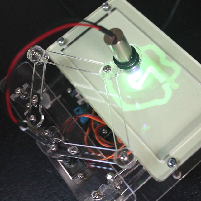
Elektor Labs Elektor Laser Head Upgrade for Sand Clock
The Elektor Laser Head transforms the Elektor Sand Clock into a clock that writes the time on glow-in-the-dark film instead of sand. In addition to displaying the time, it can also be used to create ephemeral drawings. The 5 mW laser pointer, with a wavelength of 405 nm, produces bright green drawings on the glow-in-the-dark film. For best results, use the kit in a dimly lit room. Warning: Never look directly into the laser beam! The kit includes all the necessary components, but soldering three wires is required. Note: This kit is also compatible with the original Arduino-based Sand Clock from 2017. For more details, see Elektor Magazine 1-2/2017 and Elektor Magazine 1-2/2018.
€ 34,95€ 24,95Best Price
-
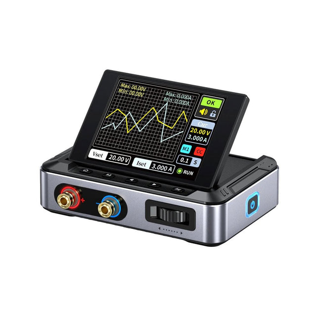
FNIRSI FNIRSI DPS150 DC Power Supply (150 W)
The FNIRSI DPS150 is a high-performance adjustable DC power supply that features a USB-C input interface and multiple power supply modes, allowing precise adjustment of output voltage (0-30 V) and current (0-5 A). It provides efficient, low-consumption, and stable output, equipped with multiple safety protection functions including overvoltage, overcurrent, overload, overheating, and reverse connection. It can be flexibly applied to serial connection of multiple devices, with rich and user-friendly display and operation, compact and portable design, meeting various application needs. Features 30 V, 5 A, 150 W variable DC power with 0.01 V, 0.001 A precision, CC/CV modes, and <20 mV ripple to protect sensitive electronics. Supports PC, QC, and DC inputs with programmable outputs and 6 preset voltage/current settings. Compatible with 4 mm banana plugs, U-shaped terminals, and copper wires for various equipment. 8 safety mechanisms including overvoltage, current, short circuit, and overheating protection. 2.8-inch HD IPS screen with 90° flip, numerical and curve displays for easy monitoring. Small, space-saving design for use in labs, repairs, and DIY projects. Specifications Input Voltage 5~32 V DC Input Current 100 mA-5 A Output Voltage 0-30 V Output Current 0~5 A Output Power 0-150 W Input Way PD fast charger QC fast charger Power bank DC power adapters Operating Environment 0-40°C Load Regulation 0.49% Full Load Efficiency 96.30% Display 2.8 inch (320 x 240) Dimensions 106 x 76 x 28 mm Weight 178 g Included 1x DPS150 Power Supply 2x Alligator clip wires (black & red) 1x Micro USB cable 1x Manual Downloads Manual Firmware V0.0.1
€ 59,00
-
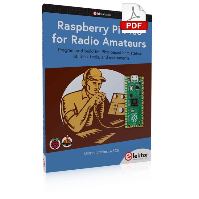
Elektor Digital Raspberry Pi Pico for Radio Amateurs (E-book)
Program and build RPi Pico-based ham station utilities, tools, and instruments Although much classical HF and mobile equipment is still in use by large numbers of amateurs, the use of computers and digital techniques has now become very popular among amateur radio operators. Nowadays, anyone can purchase a €5 Raspberry Pi Pico microcontroller board and develop many amateur radio projects using the “Pico” and some external components. This book is aimed at amateur radio enthusiasts, Electronic Engineering students, and anyone interested in learning to use the Raspberry Pi Pico to shape their electronic projects. The book is suitable for beginners in electronics as well as for those with wide experience. Step-by-step installation of the MicroPython programming environment is described. Some knowledge of the Python programming language is helpful to be able to comprehend and modify the projects given in the book. The book introduces the Raspberry Pi Pico and gives examples of many general-purpose, software-only projects that familiarize the reader with the Python programming language. In addition to the software-only projects tailored to the amateur radio operator, Chapter 6 in particular presents over 36 hardware-based projects for “hams”, including: Station mains power on/off control Radio station clock GPS based station geographical coordinates Radio station temperature and humidity Various waveform generation methods using software and hardware (DDS) Frequency counter Voltmeter / ammeter / ohmmeter / capacitance meter RF meter and RF attenuators Morse code exercisers RadioStation Click board Raspberry Pi Pico based FM radio Using Bluetooth and Wi-Fi with Raspberry Pi Pico Radio station security with RFID Audio amplifier module with rotary encoder volume control Morse decoder Using the FS1000A TX-RX modules to communicate with Arduino
€ 32,95
Members: € 29,66
-

Elektor Digital Raspberry Pi Pico W en un tournemain (PDF)
Maîtrise de la puce RP2040 avec plus de 60 projets à réaliser et à programmer Les cartes Raspberry Pi Pico et Pico W sont animées par un microcontrôleur ARM Cortex M0+ RP2040 à double coeur, rapide, efficace et peu coûteux, qui fonctionne jusqu'à 133 MHz et dispose de 264 Ko de SRAM et de 2 Mo de mémoire Flash. Outre une vaste mémoire, le Pico et le Pico W disposent de nombreuses broches GPIO et d'interfaces telles que CA/N, SPI, I²C, UART, MLI, de fonctions de temporisation, d'une interface de débogage matériel et d'un capteur de température interne. La carte Raspberry Pi Pico W comporte en plus une puce CYW43439 Bluetooth et Wi-Fi d'Infineon. Au moment de la rédaction de ce livre, le micrologiciel Bluetooth pour le Pico W n'était pas encore disponible. Le Wi-Fi à 2,4 GHz est toutefois entièrement pris en charge avec les protocoles 802.11b/g/n. Ce livre est une introduction à l'utilisation du Raspberry Pi Pico W avec le langage de programmation MicroPython. Les quelque soixante projets testés et opérationnels sont présentés à l'aide de l'environnement de développement intégré (EDI) Thonny. Les sujets abordés sont nombreux : Installation de MicroPython sur le Raspberry Pi Pico depuis un PC Interruptions de l'horloge et interruptions externes Convertisseur analogique-numérique (CA/N) Capteurs de température interne et externe Capteurs externes (pression, humidité, pouls, à ultrasons) Enregistrement de données MLI, UART, I²C et SPI Bluetooth, Wi-Fi et applis sur smarphone Convertisseur numérique-analogique (CN/A) Tous les projets ont été testés et éprouvés. Ils peuvent être mis en oeuvre sur le Raspberry Pi Pico ainsi que sur le Raspberry Pi Pico W. Toutefois les projets avec une liaison Wi-Fi ne fonctionnent que sur le Pico W. Une petite expérience en programmation et en électronique est nécessaire pour suivre les projets. De brèves descriptions, des schémas fonctionnels, des schémas détaillés du câblage des montages et des listings MicroPython complets sont fournis pour tous les projets.
€ 34,95
Members: € 31,46
-

JOY-iT JOY-iT PS1440-C-Pro Programmable Laboratory Power Supply with RS485 (1440 W)
With the JOY-iT PS1440-C-Pro, you get a programmable laboratory power supply that delivers DC voltages ranging from 0.01 to 60 V and DC currents from 0.01 to 24 A at the voltage output. The intuitive control panel allows you to program, store, and recall up to 9 different DC voltage settings. You can also configure individual protection and limiting functions—such as overvoltage protection. All settings are easily adjusted via the keypad and/or rotary control and are clearly shown on the high-resolution 2.4" color display. For enhanced connectivity, the PS1440-C-Pro includes an RS485 interface for robust, long-distance communication. This makes it ideal for complex setups where signal stability, noise immunity, and reliable data transfer are critical. The included connector ensures a secure connection, improving the overall reliability and performance of your laboratory equipment setup. Features Complete device ready for immediate use RS485 interface Battery charging function Values can be entered conveniently via keypad Over current & over voltage protection adjustable Integrated RTC, NTC temperature sensor Included detailed documentation in English, German & French Specifications Input voltage 230 V Output voltage 060 V Output current 0-24 A Output power 0-1440 W Input voltage accuracy ±1% +5 digits Output voltage accuracy ±0.3% +3 digits Output current accuracy ±0.5% +5 digits Battery voltage ±0.5% +3 digits Input voltage measurement resolution 0.01 V Output voltage measurement resolution 0.01 V Current measurement resolution 0.01 V Battery voltage measurement resolution 0.01 V Response time in constant voltage mode 2 ms @ 0.1-5 A Load regulation in constant voltage mode ±0.1% +2 digits Load regulation in constant current mode ±0.1% +3 digits Measuring range electric charge 0-9999.99 Ah Measuring range energy 0-9999.99 Wh Statistical errors in electric charge & energy ±2% Output ripple 100 mV VPP @ 12 V150 mV VPP @ 24 V Sensor temperature detection range −10~100°C (0-200°F) Sensor temperature detection accuracy ±3°C (±6°F) Working mode Step-down operation Screen brightness setting Level 0-5, 6 levels in total Permissible working temperature −10~40°C (0-104°F) Dimensions 170 x 93 x 340 mm Included JOY-iT PS1440-C Power Supply 2-pin connector for RS485 interface Power cord Manual Downloads Datasheet MODBUS Protocol PC Software Driver for Windows
€ 499,00
Members: € 449,10
-
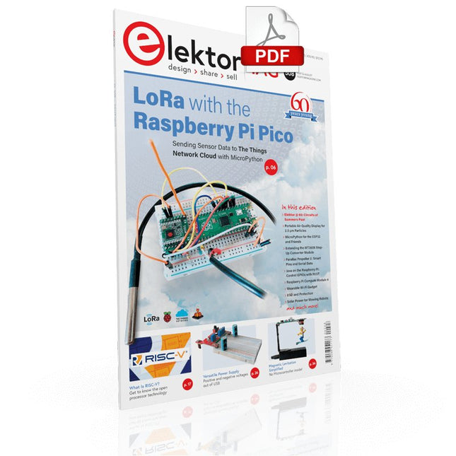
Elektor Digital Elektor July/August 2021 (PDF) EN
LoRa with the Raspberry Pi PicoFun with MicroPython What Is RISC-V?And Why the Industry Is So Excited About a New Processing Core! Elektor @ 60Circuits of Summer Past Versatile Power Supply for BreadboardsPositive and Negative Voltages Out of 5 V from USB Raspberry Pi Pico EssentialsSample Chapter: Wi-Fi with the Raspberry Pi Pico Magnetic Levitation the Easy Way Hands On the Parallax Propeller 2Part 3: Smart Pins and Serial Data (UART) Nucleo Boards Programming with the STM32CubeIDESample Chapter: FreeRTOS for the STM32 MCU Developer's ZoneTips & Tricks, Best Practices and Other Useful Information Miniware DT71 Digital Tweezers Wearable Wi-Fi Gadget: ESPHome Does the Job Again Starting out in ElectronicsEasier Than Imagined! This Concludes the Subject of “Capacitors” Simple Sketches Using the Qwiic Ecosystem Java on the Raspberry Pi (Part 2)Controlling GPIOs with a Spring REST Service Raspberry Pi Compute Module 4A Raspberry Pi for Industry Portable, Stand-Alone Air Quality Display for 2.5 µm ParticlesKeep(s) an Eye on Your Health From Life’s ExperienceThe Future Was Better in the Past MicroPython for the ESP32 and FriendsPart 1: Installation and Our First Programs Charge-Coupled Devices in OscilloscopesPeculiar Parts, the series ESD – The Invisible DestroyerComponents Trashed by a Bolt from the Blue Solar Power for Mowing RobotsEcological, Inexpensive, Simple! Europe’s Efforts to Tame Big Tech HexadokuThe Original Elektorized Sudoku
€ 7,50
-

Elektor Digital Raspberry Pi 4 und Pico (PDF)
Pfiffige Projekte zum Messen, Steuern und Regeln Der Raspberry Pi dominiert seit vielen Jahren die Maker-Szene. Frei verfügbare I/O-Pins machten ihn zu einem der beliebtesten Prozessorboards aller Zeiten. Allerdings verfügt der klassische Raspberry Pi über keinerlei Analogeingänge. Eine direkte Messung analoger Werte ist damit nicht möglich. So können weder Photodioden noch NTCs oder Hallsensoren etc. unmittelbar ausgelesen werden. Zudem sind die Pins direkt, d. h. ohne Treiber oder Schutzschaltung, mit den freiliegenden Kontakten verbunden. Dadurch kann der zentrale Controller und damit der gesamte Raspberry Pi schnell zerstört werden. Mit dem Pico können diese Probleme elegant gelöst werden. Er kann als sogenanntes „Frontend“ problemlos vielfältige Messaufgaben übernehmen. Zudem ist der Pico deutlich preisgünstiger als ein klassischer Raspberry Pi 4. Falls eine Fehlbeschaltung zur Zerstörung des Pico führt, ist dies vor allem für nicht-professionelle Anwender relativ leicht zu verkraften. Der klassische Raspberry Pi und der Pico werden so zum idealen Duo. Das Buch führt entsprechend in das weite und hochaktuelle Gebiet der modernen Controllertechnik anhand der beiden Boards „Raspberry Pi 4“ und „Raspberry Pi Pico“ ein. Neben einer tiefergehenden Einführung in die Arbeits- und Funktionsweise der Controllerboards selbst wird insbesondere auch auf die Messwerterfassung und -verarbeitung mit digitalen Prozessoren eingegangen. Insbesondere die Kombination beider Systeme bietet vielfältige und hochinteressante Möglichkeiten. Praktische Projekte aus dem Inhalt: USB-Verbindung zwischen Raspberry Pi 4 und Pico I²C-Kommunikation und Pico als I²C-Device Voltmeter und Computerthermometer Pico W als Web-Server und WLAN-Scanner Frequenzmesser und -generatoren OLED-Displays an Pico und Raspberry Pi 4 Energiesparmonitor Welche Astronauten sind im Orbit? Mini-Monitor für den aktuellen Bitcoin-Kurs
€ 32,80
Members: € 29,52
-

Elektor Labs Elektor Low-Noise Lab Power Supply
The Elektor Low-Noise Lab Power Supply is a fully analogue, adjustable, medium-power symmetrical bench supply that contains no switching or digital components. It provides an output voltage adjustable between 0 V and ±22 V, and an output current adjustable from 0 A to 1 A. Because it avoids any form of switching circuitry, the design delivers extremely low noise. To display both output voltages and currents, four miniature moving-coil panel meters are used. Most modern laboratory power supplies and AC adapters employ switch-mode techniques. Even the best examples inevitably exhibit high-frequency ripple and other switching artefacts on their output, which can interfere with the testing of sensitive analogue circuits and disturb low-level measurements. To overcome this, the concept here is a completely analogue power supply. Although less efficient than its switch-mode counterparts, the reduced efficiency is of little importance for test-bench use and ensures cleaner, more reliable measurement results. Because many analogue circuits require a symmetrical supply, this design delivers positive and negative output voltages of equal magnitude. A small amount of adjustment is available to compensate for any imbalance. Naturally, a variable current-limit function is also included. The kit includes the components required to build the power supply, except for the transformers. Specifications Output Voltage 0…+22 V, 0, −22 V Output Current 0…+1 A, 0…−1 A Noise −85 dBV, (at 0.95 A/20 V, B = 22 kHz) −84 dBV (at 0.95 A/20 V, B > 500 kHz) Ripple 50 µVRMS (at 950 mA/20 V, B = 22 kHz, mainly 100 Hz component) Included 3x PCBs: Regulator (PCB-1), Mains Filter (PCB-2) and Transformer (PCB-3) All the components except the AC transformers 4x moving-coil meters Additional parts for wiring (wires, banana sockets, IEC Power entry module, etc.) Not included The three AC transformers An enclosure Parts List For the Regulator PCB (240386-1) Resistors (250 mW, 1%) R1 = 12 Ω R2, R8, R37, R62 = 1 MΩ R3, R7, R10, R13, R17, R20, R22, R30, R35, R42, R45, R47, R55, R60 = 100 Ω, 600 mW R4, R5 = 4.7 kΩ R6 = 100 kΩ R9, R12, R14, R36, R38, R39, R61, R63, R66, R72, R78, R79 = 10.0 kΩ, 600 mW R11 = 9.76 kΩ, 600 mW R15, R40 = 44.2 kΩ, 600 mW R16, R41, R77 = 1 kΩ R18, R43 = 1.5 kΩ, 1 W, 5% R19, R44 = 470 Ω, 1 W, 5% R21, R46 = 330 Ω, 600 mW R23, R24, R48, R49 = 1.0 Ω, 1 W R25, R50 = 1 kΩ, 1 W, 5% R26, R28, R51, R53 = 1.000 kΩ 0.1%, 15 ppm/C R27, R29, R52, R54 = 10.00 kΩ 0.1%, 15 ppm/C R31, R56 = 1.2 kΩ, 1 W, 5% R32, R57 = 47 kΩ R33, R58 = 270 Ω R34, R59 = 27 kΩ R64, R69 = 12.0 kΩ R65 = 3.0 kΩ, 600 mW R67, R80 = 470 Ω, 600 mW R68, R70 = 6.8 kΩ, 600 mW R71 = 30.0 kΩ,, 600 mW R73, R74, R75, R76 = 10 MΩ P1, P2, P3 = 10 kΩ, 200 mW, 20%, potentiometer, 1 turns, single, lin., panel mount P4, P5 = 500 Ω, 500 mW, 10%, trimmer, 25 turns, 3296Y-1-501LF Bourns P6, P7 = 10 kΩ, 500 mW, 10%, trimmer, 25 turns, 3296Y-1-501LF Bourns Capacitors C1 = 100 nF, 50 V, 10%, ceramic X7R, LS 5 mm C2, C3, C6, C7, C30 = 10 µF, 63V, 20%, LS 2.5 mm, 3000hours@105°C C4, C5, C8, C9, C13, C14, C18, C19, C23, C24, C28, C29, C31, C32, C38, C39 = 100 nF, 250 V, 10%, PET, LS 7.5 mm C10, C20 = 47 nF, 100 V, 5%, PET, LS 5 mm C11, C21 = 10 nF, 100 V, 5%, PET, LS 5 mm C12, C22 = 220 µF, 35 V, 20%, 0.024 Ω, LS2.5/3.5 mm, Ir 3.4 A, 2000hours@125°C, polymer C15, C25 = 120 µF, 50 V, 20%, ESR 0.02 Ω, Diam. 10 mm max., LS 5 mm C16, C26 = 15 nF, 100 V, 5%, PET, LS 5 mm C17, C27 = 47 nF, 100 V, 5%, PET, LS 5 mm C33, C34 = 22 µF, 50 V, 20%, LS 2 mm, 10000 hours @ 105°C C35, C36, C44, C45 = 1 µF, 100 V, 10%, LS 5 mm, ceramic X7R C37 = 100 uF, 50 V, 20%. LS 3.5 mm C40, C41, C42, C43, C46, C47, C48, C49 = 1000 µF, 50 V, 20%, LS 5/7.5 mm, Ir 3.32 A, 10000hours@105°C, D 16 mm C50, C51, C52, C53 = 47 nF, 100 V, 10%, ceramic X7R, LS 5 mm Inductors L1, L2 = 4.7 µH, 3.2 A, 0.033 Ω, LS 5 mm, RLB0914-4R7ML Bourns L3 = Commom mode choke, 14.5 mH, 3 A, SSRH24NH-30145 Kemet Semiconductors D1, D2, D3, D4, D5, D9, D10, D11, D15 = BAT85, DO-34 D6, D7, D12, D13 = SR560, DO-201AD D8, D14, D16 = 1N4148, DO-35 D17 = Zenerdiode, 5.6 V, 0.5 W, DO-41 D18, D19 = 1N4004, DO-41 D20, D21 D22, D23 = V30100CI-M3/P, dual common cathode, TO-220 D24 = Zener diode, 30 V, 1 W, DO-41 LED1, LED2 = LED, red, T-1 (3 mm) LED3, LED4 = LED, green, T-1 (3 mm) TVS1, TVS2 = BZW50-33B, R6 T1, T2, T4 = BC337.25, TO-92 T3 = NJW0302G, TO-3P T5, T6, T8 = BC327.25, TO-92 T7 = NJW0281G, TO-3P T9 = BD139, TO-126 (SOT-32) IC1 = LM334Z, TO-92 IC2 = LM4040AIZ-5.0/NOPB, TO-92 (TO-226AA-3) IC3, IC4 = OPA2992IDR, SOIC-8 IC5, IC6 = OPA4992IDR, SOIC-14 IC7 = OPA992IDBVR, SOT-23-5 IC8 = LM339N, DIP-14 IC9 = LM317, TO-220 IC10 = LM337, TO-220 Others F1, F2 = 5×20 mm fuse, 1.6 A, fast acting HS1, HS2 = Heatsink MC33271 (for T3/T7), 2.7°C/W, PCB mount, height 63.5 mm K1, K4 = 3-way screw terminal block, LS 3.5 mm, max. 1.5 mm² K2, K3 = 3-way screw terminal block, LS 3.5 mm, max. 1 mm² M1, M3 = Moving coil meter, Range 30 V, type 91C4, 45×45 mm M2, M4 = Moving coil meter, Range 1 A, type 91C4, 45×45 mm² RE1 = Relay DPDT,5V, UA2-5NU Miscellaneous 3× 3-way screw terminal block, LS 3.5 mm, max. 1 mm² (for P1, P2, P3) 4× Pin header, 1×2, vertical, pitch 2.54 mm (for LED1, LED2, LED3, LED4) 4× Pin socket, 1×2, vertical. pitch 2.54 mm (for LED1, LED2, LED3, LED4) 2× Heatsink FK222SA220, 20°C/W, PCB mount (for IC9 & IC10) 2× Mica thermal pad for TO-220, 12×18×0.05 mm (for IC9 & IC10) 2× Insulating bushing IB 6, TO-220 (for IC9 & IC10) 2× Ceramic thermal pad, 23×20×2 mm (for T3 & T7) 2× PCB Fuse Holder, for 5×20 mm fuse, 10 A (for F1, F2) 2× Cover for PCB Fuse Holder, transparent (for F1, F2) 2× 2-way screw terminal block, LS 3.5 mm, max. 1 mm² (for M1 & M3) 2× 2-way screw terminal block, LS 3.5 mm, max. 1.5 mm² (for M2 & M4) 8× M3 solder lug, thickness 0.35 mm (for M1…M4) M4 solder lug, thickness 0.35 mm (to connect 4 mm banana connectors) Screened cable, 1 pair, 2×24 AWG/0.22 mm², 1 m (for P1, P2 & P3) IC socket, DIP, 14 contacts (for IC8) M3 washer, plain, steel M3 screw, 16 mm, steel, pan head M3 nut M3 spring washer 50 mm M3 standoff, steel, male-female 12 mm M3 standoff, steel, male-female 10 mm M3 standoff, steel, male-female M3 screw, 8 mm, steel, pan head For the Mains Fiter PCB (240386-2) Resistor R1 = 220 kΩ, 1 W, 500 V, 5% Capacitors C1, C2 = 470 nF, 305 VAC, Class X2, 11 × 27 mm max., LS 15/22.5 mm C3, C4, C5, C6 = 2.2 nF, 300 VAC, Class Y2, 13 × 4 mm, LS 10 mm, PP Inductors L1, L2 = Common-mode choke, 6.8 mH, 1.7 A, TDK B82732R2172B030 Semiconductor MOV1 = TVS varistor, 300 VAC, S14K300 (230 VAC, B72214S0301K101) and SK14K150 (150 VAC, B72214S0151K101) Others K1, K2 = 3-way screw terminal block, LS 7.62 mm F1 = Time-delay fuse, 0.5 A (230 VAC) or 1 A (115 VAC) Miscellaneous 1× Fuse holder, 5×20 mm, 10 A, 500 VAC 1× Transparent fuse cover 4× 10 mm M3 standoff, steel, male–female 4× M3 screw, 8 mm, steel, pan head 4× M3 nut For the Transformer PCB (240386-3) Resistors R1, R2 = 2.7 kΩ, 600 mW, 1% R3 = 10.0 kΩ, 600 mW, 1% Capacitor C1 = 220 µF, 50 V, 20%, Ø10 mm, LS 5 mm, 4000 h @ 105°C Transformers (not included in this kit!) TR1, TR2, TR3 = 2×7 V, 25 VA, PCB-mounted toroid, 70060K Talema Semiconductors D1–D4 = 1N4148, DO-35 D5, D6 = 1N4004, DO-41 D7 = Zener 5.6 V, 1.3 W, DO-41 LED1 = LED, red, T-1 (3 mm) IC1, IC2 = MOC8021M, CTR ≥ 1000%, DIP-6 Others F1, F2, F3 = 160 mA time-delay fuse (230 VAC) or 315 mA time-delay fuse (115 VAC) K1 = 2-way screw terminal block, LS 7.62 mm K2 = 3-way screw terminal block, LS 3.5 mm, max 1.5 mm² K3, K4 = 3-way screw terminal block, LS 3.5 mm, max 1 mm² RE1, RE2 = Relay DPDT, 5 A/250 VAC / 24 VDC Miscellaneaous 1× Pin header 1×2, pitch 2.54 mm + matching socket for LED1 3× Fuse holder 5 × 20 mm, 10 A, 500 VAC + transparent cover 3× M4 screw, 8 mm, pan head + washer for TR1-TR3 8× M3 screw, 8 mm, pan head + nut + washer 8× 10 mm M3 standoff, steel, male–female 2× IC socket, DIP-6 for IC1 & IC2 Additional Parts 1 m red insulated wire, stranded, 1.5 mm² 0.5 m blue insulated wire, stranded, 1.5 mm² 0.5 m black insulated wire, stranded, 1.5 mm², 0.5 m 2 m red insulated wire, stranded, D 0.56 mm (0.25 mm²) 2 m black insulated wire, stranded, D 0.56 mm (0.25 mm²) 0.5 m Multicore Cable, Flexible, 3 Core, 0.75 mm² (24 x 0.2 mm) Red banana socket Black banana socket Blue banana socket Green banana socket IEC Power Entry Module with switch, IEC C14 3 crimp terminals, FASTON, 4.75 x 0.81 mm 3 knobs Links Elektor Labs JumpStarter Page Article (Part 1) Article (Part 2)
€ 299,00€ 249,00Best Price


