
Search results for "avr OR max OR chess OR computer OR pcb"
-

Elektor Labs Elektor Low-Noise Lab Power Supply
The Elektor Low-Noise Lab Power Supply is a fully analogue, adjustable, medium-power symmetrical bench supply that contains no switching or digital components. It provides an output voltage adjustable between 0 V and ±22 V, and an output current adjustable from 0 A to 1 A. Because it avoids any form of switching circuitry, the design delivers extremely low noise. To display both output voltages and currents, four miniature moving-coil panel meters are used. Most modern laboratory power supplies and AC adapters employ switch-mode techniques. Even the best examples inevitably exhibit high-frequency ripple and other switching artefacts on their output, which can interfere with the testing of sensitive analogue circuits and disturb low-level measurements. To overcome this, the concept here is a completely analogue power supply. Although less efficient than its switch-mode counterparts, the reduced efficiency is of little importance for test-bench use and ensures cleaner, more reliable measurement results. Because many analogue circuits require a symmetrical supply, this design delivers positive and negative output voltages of equal magnitude. A small amount of adjustment is available to compensate for any imbalance. Naturally, a variable current-limit function is also included. The kit includes the components required to build the power supply, except for the transformers. Specifications Output Voltage 0…+22 V, 0, −22 V Output Current 0…+1 A, 0…−1 A Noise −85 dBV, (at 0.95 A/20 V, B = 22 kHz) −84 dBV (at 0.95 A/20 V, B > 500 kHz) Ripple 50 µVRMS (at 950 mA/20 V, B = 22 kHz, mainly 100 Hz component) Included 3x PCBs: Regulator (PCB-1), Mains Filter (PCB-2) and Transformer (PCB-3) All the components except the AC transformers 4x moving-coil meters Additional parts for wiring (wires, banana sockets, IEC Power entry module, etc.) Not included The three AC transformers An enclosure Parts List For the Regulator PCB (240386-1) Resistors (250 mW, 1%) R1 = 12 Ω R2, R8, R37, R62 = 1 MΩ R3, R7, R10, R13, R17, R20, R22, R30, R35, R42, R45, R47, R55, R60 = 100 Ω, 600 mW R4, R5 = 4.7 kΩ R6 = 100 kΩ R9, R12, R14, R36, R38, R39, R61, R63, R66, R72, R78, R79 = 10.0 kΩ, 600 mW R11 = 9.76 kΩ, 600 mW R15, R40 = 44.2 kΩ, 600 mW R16, R41, R77 = 1 kΩ R18, R43 = 1.5 kΩ, 1 W, 5% R19, R44 = 470 Ω, 1 W, 5% R21, R46 = 330 Ω, 600 mW R23, R24, R48, R49 = 1.0 Ω, 1 W R25, R50 = 1 kΩ, 1 W, 5% R26, R28, R51, R53 = 1.000 kΩ 0.1%, 15 ppm/C R27, R29, R52, R54 = 10.00 kΩ 0.1%, 15 ppm/C R31, R56 = 1.2 kΩ, 1 W, 5% R32, R57 = 47 kΩ R33, R58 = 270 Ω R34, R59 = 27 kΩ R64, R69 = 12.0 kΩ R65 = 3.0 kΩ, 600 mW R67, R80 = 470 Ω, 600 mW R68, R70 = 6.8 kΩ, 600 mW R71 = 30.0 kΩ,, 600 mW R73, R74, R75, R76 = 10 MΩ P1, P2, P3 = 10 kΩ, 200 mW, 20%, potentiometer, 1 turns, single, lin., panel mount P4, P5 = 500 Ω, 500 mW, 10%, trimmer, 25 turns, 3296Y-1-501LF Bourns P6, P7 = 10 kΩ, 500 mW, 10%, trimmer, 25 turns, 3296Y-1-501LF Bourns Capacitors C1 = 100 nF, 50 V, 10%, ceramic X7R, LS 5 mm C2, C3, C6, C7, C30 = 10 µF, 63V, 20%, LS 2.5 mm, 3000hours@105°C C4, C5, C8, C9, C13, C14, C18, C19, C23, C24, C28, C29, C31, C32, C38, C39 = 100 nF, 250 V, 10%, PET, LS 7.5 mm C10, C20 = 47 nF, 100 V, 5%, PET, LS 5 mm C11, C21 = 10 nF, 100 V, 5%, PET, LS 5 mm C12, C22 = 220 µF, 35 V, 20%, 0.024 Ω, LS2.5/3.5 mm, Ir 3.4 A, 2000hours@125°C, polymer C15, C25 = 120 µF, 50 V, 20%, ESR 0.02 Ω, Diam. 10 mm max., LS 5 mm C16, C26 = 15 nF, 100 V, 5%, PET, LS 5 mm C17, C27 = 47 nF, 100 V, 5%, PET, LS 5 mm C33, C34 = 22 µF, 50 V, 20%, LS 2 mm, 10000 hours @ 105°C C35, C36, C44, C45 = 1 µF, 100 V, 10%, LS 5 mm, ceramic X7R C37 = 100 uF, 50 V, 20%. LS 3.5 mm C40, C41, C42, C43, C46, C47, C48, C49 = 1000 µF, 50 V, 20%, LS 5/7.5 mm, Ir 3.32 A, 10000hours@105°C, D 16 mm C50, C51, C52, C53 = 47 nF, 100 V, 10%, ceramic X7R, LS 5 mm Inductors L1, L2 = 4.7 µH, 3.2 A, 0.033 Ω, LS 5 mm, RLB0914-4R7ML Bourns L3 = Commom mode choke, 14.5 mH, 3 A, SSRH24NH-30145 Kemet Semiconductors D1, D2, D3, D4, D5, D9, D10, D11, D15 = BAT85, DO-34 D6, D7, D12, D13 = SR560, DO-201AD D8, D14, D16 = 1N4148, DO-35 D17 = Zenerdiode, 5.6 V, 0.5 W, DO-41 D18, D19 = 1N4004, DO-41 D20, D21 D22, D23 = V30100CI-M3/P, dual common cathode, TO-220 D24 = Zener diode, 30 V, 1 W, DO-41 LED1, LED2 = LED, red, T-1 (3 mm) LED3, LED4 = LED, green, T-1 (3 mm) TVS1, TVS2 = BZW50-33B, R6 T1, T2, T4 = BC337.25, TO-92 T3 = NJW0302G, TO-3P T5, T6, T8 = BC327.25, TO-92 T7 = NJW0281G, TO-3P T9 = BD139, TO-126 (SOT-32) IC1 = LM334Z, TO-92 IC2 = LM4040AIZ-5.0/NOPB, TO-92 (TO-226AA-3) IC3, IC4 = OPA2992IDR, SOIC-8 IC5, IC6 = OPA4992IDR, SOIC-14 IC7 = OPA992IDBVR, SOT-23-5 IC8 = LM339N, DIP-14 IC9 = LM317, TO-220 IC10 = LM337, TO-220 Others F1, F2 = 5×20 mm fuse, 1.6 A, fast acting HS1, HS2 = Heatsink MC33271 (for T3/T7), 2.7°C/W, PCB mount, height 63.5 mm K1, K4 = 3-way screw terminal block, LS 3.5 mm, max. 1.5 mm² K2, K3 = 3-way screw terminal block, LS 3.5 mm, max. 1 mm² M1, M3 = Moving coil meter, Range 30 V, type 91C4, 45×45 mm M2, M4 = Moving coil meter, Range 1 A, type 91C4, 45×45 mm² RE1 = Relay DPDT,5V, UA2-5NU Miscellaneous 3× 3-way screw terminal block, LS 3.5 mm, max. 1 mm² (for P1, P2, P3) 4× Pin header, 1×2, vertical, pitch 2.54 mm (for LED1, LED2, LED3, LED4) 4× Pin socket, 1×2, vertical. pitch 2.54 mm (for LED1, LED2, LED3, LED4) 2× Heatsink FK222SA220, 20°C/W, PCB mount (for IC9 & IC10) 2× Mica thermal pad for TO-220, 12×18×0.05 mm (for IC9 & IC10) 2× Insulating bushing IB 6, TO-220 (for IC9 & IC10) 2× Ceramic thermal pad, 23×20×2 mm (for T3 & T7) 2× PCB Fuse Holder, for 5×20 mm fuse, 10 A (for F1, F2) 2× Cover for PCB Fuse Holder, transparent (for F1, F2) 2× 2-way screw terminal block, LS 3.5 mm, max. 1 mm² (for M1 & M3) 2× 2-way screw terminal block, LS 3.5 mm, max. 1.5 mm² (for M2 & M4) 8× M3 solder lug, thickness 0.35 mm (for M1…M4) M4 solder lug, thickness 0.35 mm (to connect 4 mm banana connectors) Screened cable, 1 pair, 2×24 AWG/0.22 mm², 1 m (for P1, P2 & P3) IC socket, DIP, 14 contacts (for IC8) M3 washer, plain, steel M3 screw, 16 mm, steel, pan head M3 nut M3 spring washer 50 mm M3 standoff, steel, male-female 12 mm M3 standoff, steel, male-female 10 mm M3 standoff, steel, male-female M3 screw, 8 mm, steel, pan head For the Mains Fiter PCB (240386-2) Resistor R1 = 220 kΩ, 1 W, 500 V, 5% Capacitors C1, C2 = 470 nF, 305 VAC, Class X2, 11 × 27 mm max., LS 15/22.5 mm C3, C4, C5, C6 = 2.2 nF, 300 VAC, Class Y2, 13 × 4 mm, LS 10 mm, PP Inductors L1, L2 = Common-mode choke, 6.8 mH, 1.7 A, TDK B82732R2172B030 Semiconductor MOV1 = TVS varistor, 300 VAC, S14K300 (230 VAC, B72214S0301K101) and SK14K150 (150 VAC, B72214S0151K101) Others K1, K2 = 3-way screw terminal block, LS 7.62 mm F1 = Time-delay fuse, 0.5 A (230 VAC) or 1 A (115 VAC) Miscellaneous 1× Fuse holder, 5×20 mm, 10 A, 500 VAC 1× Transparent fuse cover 4× 10 mm M3 standoff, steel, male–female 4× M3 screw, 8 mm, steel, pan head 4× M3 nut For the Transformer PCB (240386-3) Resistors R1, R2 = 2.7 kΩ, 600 mW, 1% R3 = 10.0 kΩ, 600 mW, 1% Capacitor C1 = 220 µF, 50 V, 20%, Ø10 mm, LS 5 mm, 4000 h @ 105°C Transformers (not included in this kit!) TR1, TR2, TR3 = 2×7 V, 25 VA, PCB-mounted toroid, 70060K Talema Semiconductors D1–D4 = 1N4148, DO-35 D5, D6 = 1N4004, DO-41 D7 = Zener 5.6 V, 1.3 W, DO-41 LED1 = LED, red, T-1 (3 mm) IC1, IC2 = MOC8021M, CTR ≥ 1000%, DIP-6 Others F1, F2, F3 = 160 mA time-delay fuse (230 VAC) or 315 mA time-delay fuse (115 VAC) K1 = 2-way screw terminal block, LS 7.62 mm K2 = 3-way screw terminal block, LS 3.5 mm, max 1.5 mm² K3, K4 = 3-way screw terminal block, LS 3.5 mm, max 1 mm² RE1, RE2 = Relay DPDT, 5 A/250 VAC / 24 VDC Miscellaneaous 1× Pin header 1×2, pitch 2.54 mm + matching socket for LED1 3× Fuse holder 5 × 20 mm, 10 A, 500 VAC + transparent cover 3× M4 screw, 8 mm, pan head + washer for TR1-TR3 8× M3 screw, 8 mm, pan head + nut + washer 8× 10 mm M3 standoff, steel, male–female 2× IC socket, DIP-6 for IC1 & IC2 Additional Parts 1 m red insulated wire, stranded, 1.5 mm² 0.5 m blue insulated wire, stranded, 1.5 mm² 0.5 m black insulated wire, stranded, 1.5 mm², 0.5 m 2 m red insulated wire, stranded, D 0.56 mm (0.25 mm²) 2 m black insulated wire, stranded, D 0.56 mm (0.25 mm²) 0.5 m Multicore Cable, Flexible, 3 Core, 0.75 mm² (24 x 0.2 mm) Red banana socket Black banana socket Blue banana socket Green banana socket IEC Power Entry Module with switch, IEC C14 3 crimp terminals, FASTON, 4.75 x 0.81 mm 3 knobs Links Elektor Labs JumpStarter Page Article (Part 1) Article (Part 2)
€ 249,00
Best Price
-
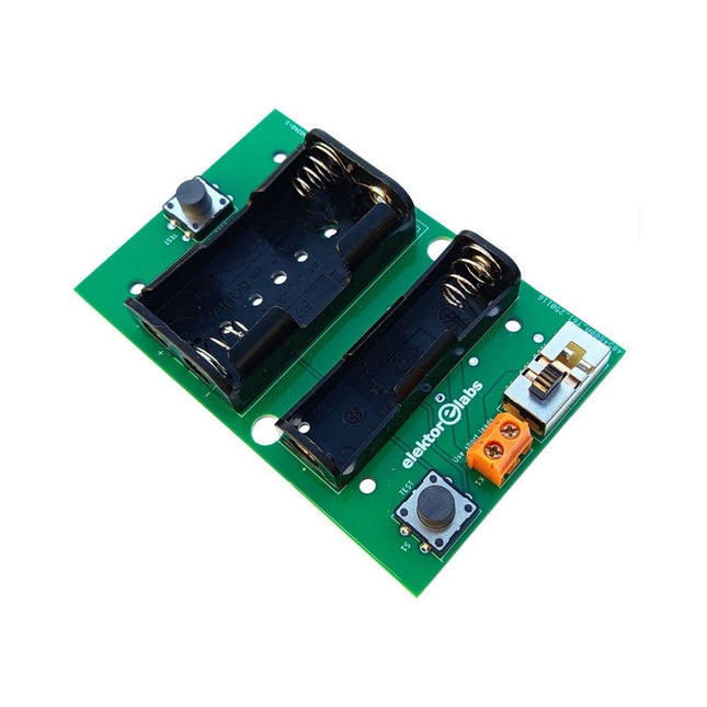
Elektor Labs Elektor Milliohmmeter Adapter
The Elektor Milliohmmeter Adapter uses the precision of a multimeter to measure very low resistance values. It is an adapter that converts a resistance into a voltage that can be measured with a standard multimeter. The Elektor Milliohmmeter Adapter can measure resistances below 1 mΩ using a 4-wire (Kelvin) method. It is useful for locating short circuits on printed circuit boards (PCB). The adapter features three measurement ranges – 1 mΩ, 10 mΩ, and 100 mΩ – selectable via a slide switch. It also includes onboard calibration resistors. The Elektor Milliohmmeter Adapter is powered by three 1.5 V AA batteries (not included). Specifications Measurement ranges 1 mΩ, 10 mΩ, 100 mΩ, 0.1% Power supply 3x 1.5 V AA batteries (not included) Dimensions 103 x 66 x 18 mm (compatible with Hammond 1593N-type enclosure, not included) Special feature On-board calibration resistors Downloads Documentation
€ 34,95
Members: € 31,46
-
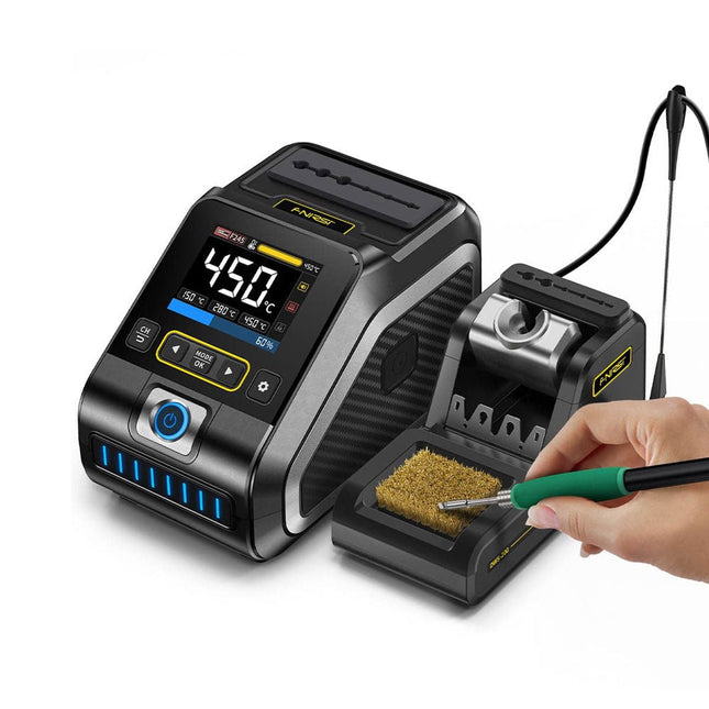
FNIRSI FNIRSI DWS-200 Smart Soldering Station (with F245 Handle + 6 Soldering Tips)
The FNIRSI DWS-200 is a powerful 200 W smart soldering station, ideal for electronic soldering applications. Powered by a switch-mode power supply, it operates smoothly with a wide voltage input range of 100-240 V. The station provides an adjustable temperature range from 100°C to 450°C (212°F to 842°F) and allows for easy switching between °C and °F. To enhance efficiency, it supports up to three preset temperature values and can connect to a soldering iron stand for standby mode activation. The station also features a dynamic temperature curve mode for real-time data monitoring, ensuring precise and consistent performance in demanding soldering tasks. Features Maximum power output of 200 W, allowing for fast heating Wide adaptive voltage input of 100-240 V 2.8" HD color TFT display with intelligent control Multiple preset groups to switch between different settings quickly Supports F245 and F210 soldering handle types, offering flexibility for different soldering applications Real-time sleep mode to extend the life of the soldering tip Multi-mode real-time monitoring for power and temperature status, enhancing safety and precision Specifications Peak Power 200 W (max) Temperature Range 100°C~450°C (212°F~842°F) Display 2.8" TFT HD Color Screen Heating Time 1 sec Melting Time 3 sec Input Voltage 100-240 V (AC) Input Fuse 3 A Soldering Handle Type F245 Dimensions (Station) 156 x 96 x 103 mm Weight (Station) 475 g Included 1x FNIRSI DWS-200 Soldering Station 1x Soldering Handle F245 6x Soldering Tips (B, KU, K, C2, I, JS) 1x Connecting Cable 2x Helping Hands 1x Power Cable (EU) Downloads Manual Firmware V1.3
€ 179,00
-

Elektor 11-12/2025 (DE)
Diese Ausgabe steht allen GOLD- und GREEN-Mitgliedern auf der ElektorMagazine-Website zum Download bereit! Sie sind noch kein Mitglied? Hier klicken! Relio v1.0 – Anwesenheitserkennung und FernsteuerungEin Matter-fähiger Smart-Controller für Hausgeräte Bessere Leiterplatten entwerfenEin praxisnaher Leitfaden für Profis und Maker KiCad 9Die wichtigsten neuen und aktualisierten Funktionen Präzisions-Picoamperemeter (Teil 1)Mit Kennlinienschreiber-Funktion bis in den pA-Bereich Analoger Pipeline-VerzerrerEin cooler Audioeffekt für Gitarren und andere Instrumente Halogene in LötmittelnFakten statt Mythen 100-mV-Durchgangsprüfer Wer treibt die europäische Elektronik voran?Unternehmen im Fokus productronica 2025Neuheiten in Elektronikentwicklung und -fertigung Automatisierung bewältigt Herausforderungenwie Reshoring, Zölle und Arbeitskräftemangel Mehr als ZukunftssicherheitKreislaufwirtschaft in der Elektronik Passive BauelementeVerlustarme Induktivitäten für hocheffiziente DC/DC-Wandler PCB-Produktion im WandelDesktop-Maschinen eröffnen neue Wege für die Leiterplattenfertigung Aller Anfang ...... braucht Spannung UHD-Displays mühelos ansteuernIhr Leitfaden, um unterschiedliche TFT-LCDs schnell in Betrieb zu nehmen Löten im Jahr 2025Praktische Tipps direkt von der Werkbank Weihnachtsstern 2025Ein Stern wird gelötet SimulIDEEin All-in-One-Werkzeug für die Schaltungsentwicklung 2025: Eine KI-OdysseeVom Autovervollständiger zum Kollegen Wortreicher WeihnachtsbaumEin festliches Elektronikprojekt mit verbalem Highlight Projekt 2.0Korrekturen, Updates und Leserbriefe ESP32-Audio-Transceiver-Board (Teil 3)Stereosender und Dual Radio
€ 15,90
-

Elektor Publishing Programming Microcontrollers in C/C++ Using Arduino
With Examples for Arduino UNO, Raspberry Pi Pico and ESP32 Programming small electronic systems has never been more accessible. Tasks that once demanded expensive tools, specialized hardware, and deep electrical engineering expertise can now be tackled with low-cost development boards and approachable software. At the centre of this shift is the Arduino environment, which provides a unified and familiar way to program a wide range of microcontroller platforms—from classic AVR boards like the Arduino UNO to modern ARM-based boards such as the Raspberry Pi Pico, and powerful Wi-Fi-enabled devices like the ESP32. This book introduces embedded programming through the core idea that defines all microcontrollers: reading inputs, processing information, and controlling outputs in a predictable loop. The Arduino environment abstracts much of the hardware complexity, allowing you to focus on behaviour rather than implementation details. With just a few lines of code, you can blink LEDs, read sensors, control motors, and communicate with other devices. While the Arduino UNO, Raspberry Pi Pico, and ESP32 boards differ greatly in performance and features, they share the same fundamental building blocks: digital and analog I/O, timers, serial communication, PWM, interrupts, and power management. Learning these concepts within the Arduino framework builds skills that transfer easily across platforms and scale toward more advanced applications. By exploring multiple boards while maintaining a consistent programming approach, this book helps you progress from simple experiments to confidently produce well-structured designs—showing that embedded development can be both practical and enjoyable.
€ 29,95
Members: € 26,96
-
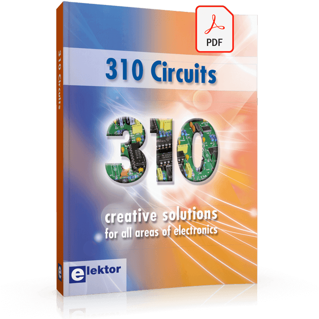
Elektor Digital 310 Circuits (E-book) EN
310 Circuits – is the 11th volume in Elektor’s renowned ‘Three Hundred’ series. 310 circuits, tips and design ideas in one book form a treasure trove for every area of electronics: audio and video, hobby and modelling, RF techniques, home and garden, test and measurement, microcontrollers, computer hardware and software, power supplies and chargers – plus of course everything else that does not seem to belong in any of these categories. 310 Circuits – contains many complete solutions as well as useful starting points for your own projects. Both categories and anything in between represent a veritable fountain of inspiration for cultivating your own ideas and learning about electronics. 310 Circuits – is a compilation of articles from ‘Summer Circuits’ editions for the years 2006, 2007 and 2008. ‘Summer Circuits’ covers the publication months July and August of Elektor magazine. 310 Circuits – is a must-have book for every creative electronics enthusiast, be it professional, enthusiast or student. 310 Circuits – for the first time has a section exclusively on robots and robotics.
€ 29,95
Members: € 26,96
-

Elektor Digital 8-Bit-Mikrocontroller (PDF)
PIC und AVR verstehen In diesem Buch werden wir uns ausschließlich mit 8-Bit-Mikrocontrollern beschäftigen, und zwar mit Mikrocontrollern der 8-Bit-PIC- und der 8-Bit-AVR-Mikrocontroller-Linien. Bei der PIC-Familie handelt es sich dabei um PIC10, PIC12, PIC16 und PIC18; bei der AVR-Familie um ATtiny, ATmega und ATxmega. Die vorgestellten 8-Bit-Chips sind für sehr viele Anwendungen vollkommen ausreichend und preislich auch attraktiv. Durch die Lektüre des Buches erhalten Sie ein fundiertes Wissen über die genannten 8-Bit-Mikrocontroller, über ihre Architektur, ihre Pinbelegungen und über ihre Programmierung. Weil wir uns in diesem Buch mit den Grundlagen der Architektur der PICs und AVRs vertraut machen möchten, werden wir auch für alle PIC- und AVR-Anwendungen Assembler einsetzen, denn die Assembler-Sprache erlaubt es, die Technik im Detail kennenzulernen. Wenn man wirklich wissen möchte, was sich im Mikrocontroller abspielt, greift man zu Assembler. Damit hat man die beste Gelegenheit, sehr nah an den Kern zu kommen. Und wenn man schon einen Mikrocontroller-Typ kennengelernt und verstanden hat, ist es bei dem nächsten deutlich einfacher, auch wenn er von einem anderen Hersteller kommt. Bei anderen Programmiersprachen bleibt die Technik immer ziemlich tief versteckt. Die Assembler-Beispiele sind so einfach gestaltet, dass sie jeder mit den im Buch aufgezeigten Programmiertechniken erstellen kann. Weil es sich um einfache Beispiele handelt, werden wir sie alle auf einer universellen Lochrasterplatine realisieren. Manche sind auch auf einem Experimentier-Breadboard umsetzbar.
€ 32,80
Members: € 29,52
-

FNIRSI FNIRSI SG-003A Signal Generator
The FNIRSI SG-003A multi-functional Signal Generator a.k.a. Process Meter/Calibrator is a high-precision voltage/current generator and meter. The SG-003A provides highly accurate reference voltages or currents for testing and calibrating other measurement instruments like multimeters and oscilloscopes. Besides voltages and currents, the SG-003A also generates rectangular pulse signals with precisely programmable frequencies and duty cycles. Its converter mode turns the SG-003A into a precision voltage-controlled current source, or current-controlled voltage source, and even a voltage- or current-controlled frequency generator. The SG-003A is a great tool for checking your multimeter’s accuracy and precision, and for testing e.g. LEDs. Features Accuracy (voltage/current) 0.1% ±0.005 Resolution (current) 0.01 mA Frequency 0-10 kHz Resolution 5 digits Output power 24 V Display 2.4" TFT LCD (320 x 240) Dimensions 92 x 72 x 30 mm Weight 165 g Specifications Signal Range Precision Resolution Max load External power supply Active current output 0~24 mA ±(0.1% + 0.005) 0.01 mA 750 Ω Passive current output (XMT) 0~24 mA ±(0.1% + 0.005) 0.01 mA 0~30 V Voltage output 0~24 V ±(0.1% + 0.005) 0.01 V 24 V loop 0~24 mA ±(0.1% + 0.005) 0.01 mA Frequency output 0~9999 Hz ±2% 5 digits Current input 0~24 mA ±(0.1% + 0.005) 0.01 mA Voltage input 0~30 V ±(0.1% + 0.005) 0.01 V Included 1x FNIRSI SG-003A Signal generator 4x Test clips 1x USB charger 1x USB-C cable 1x Manual Downloads Manual Firmware V4.3
€ 69,95
-

Elektor Digital Praxiskurs AVR-XMEGA-Mikrocontroller (E-book)
Die Mikrocontrollertechnologie ist eines der wichtigsten Gebiete der modernen Elektronik. Mikrocontroller haben sich in den letzten Jahren in allen Bereichen der modernen Technik etabliert. Der vorliegende Kurs gibt eine umfassende Einführung in die faszinierende Welt der Controllertechnik. Nach grundlegenden Betrachtungen zur Controllertechnologie wird bereits im ersten Teil des Kurses auf die praktische Umsetzung des Stoffes eingegangen. Als Basis dafür dient ein modernes Entwicklungsboard (XMEGA-A3BU Xplained), das mit einem der aktuellsten Controller des Herstellers Atmel ausgestattet ist. Der zweite Teil beschäftigt sich detailliert mit der Programmierung des Controllers. Hier kommt die Sprache „C“ zum Einsatz, da diese in der Firmware-Entwicklung eine dominierende Stellung einnimmt. Die bei weitem überwiegende Mehrheit der professionellen Entwicklungsarbeit wird in C ausgeführt. Diese Programmiersprache bietet eine umfassende Grundlage für alle Controlleranwendungen. Im dritten Teil des Kurses wird schließlich auf die hardwarenahe Programmierung eingegangen. Nach der Durchsprache von Pin-Ansteuerung, Takterzeugung und Oszillatoroptionen werden die anspruchsvolleren Themen wie Interrupts, Timer und Counter, Pulsweitenmodulation und Analog-Digitalwandlung behandelt. Der Kurs setzt auf die Philosophie des „Learning by Doing“. Er eignet sich dadurch hervorragend als praktische Ergänzung für Unterricht und Vorlesungen in Weiterführenden Schulen Technischen Berufsschulen und Fachakademien Fachhochschulen und Universitäten Aber auch der ambitionierte, nichtprofessionelle Anwender kann sich mit dem Lernmaterial einen Überblick über den neuesten Stand der Controllertechnik verschaffen.Umfangreiche Praxisbeispiele und Übungsprogramme runden den Kurs ab und lassen keine Fragen offen.
€ 34,80
Members: € 31,32
-

Elektor Januari/Februari 2025 (NL)
Elektor GREEN en GOLD leden kunnen deze uitgave hier downloaden. Nog geen lid? Klik hier om een lidmaatschap af te sluiten. DHZ-accusysteem voor zonne-energiebouw uw eigen energieopslag voor zonnepanelen Simulator voor zonnepanelentest en optimaliseer MPP-trackers en omvormers De STM32 Edge-AI-ContestOntdek de nieuwe STM32N6 en ding mee naar € 5000! Vergroten van de bandgapdaarom is er zoveel interesse in SiC en GaN Powerbank voor noteboekgeef uw oude laptop een tweede leven Medische robotshet overwinnen van technische en regelgevende barrières Vorstbescherming voor fruitbomenmet temperatuurlogger Het analoge dingde Arduino onder de analoge computers? Zuinige relaisdriverspaart 90% spoelstroom Verbetering van de ET5410A+ DC-belastingblijf koel en stil electronica 2024een terugblik Elektromagnetische compatibiliteitEMC in een notendop! Alle begin......filtert actief Reduceer vermogensverlies met seriecondensatorenslim gebruik van capacitieve reactantie De betaalbare MCP4725 12-bit digitaal/analoog-omzetterEEPROM-functie zorgt voor veilig inschakelgedrag FNIRSI LCR-ST1 smart LCR-meetpincet Raspberry Pi-gebaseerd test- en meetlabals eerste: de ADC Elektronische belastingweerstandmet onderdelen die u waarschijnlijk hebt liggen 2025: een AI-odysseeenkele projecten voor het nieuwe jaar Project-update: AmpVolt v2.0100 ampère en meer! Project 2.0correcties, updates en brieven van lezers Ethische transparantie ontsluierdinzichten uit het Ethics in Electronics 2024 onderzoek Audio DSP FX Processor Boarddeel 2: toepassingen maken
€ 14,95
-
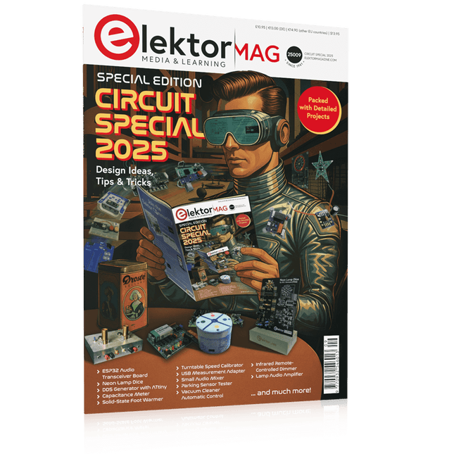
Elektor Circuit Special 2025 (EN)
Elektor GREEN and GOLD members can download their digital edition here. Not a member yet? Click here. USB Measurement AdapterTesting Current and Signal Quality of USB Ports 4...20 mA Current Output for Arduino UnoA Reliable, EMI-Insensitive Current Loop Interface Vacuum Cleaner Automatic ControlKeep Your Tools’ Work Area Clean DDS Generator with ATtiny Opamp-Tester V2New PCB – Now Also Suitable for SMDs 550-mW “Lamp” Audio AmplifierGet the Warm Sound of Vacuum Tubes With Ease Fuse GuardMonitoring a Fuse with a Flashing LED HQ RIAA PreamplifierGet the Most Out of Your Vinyl Records! Turntable Speed CalibratorAn Arduino-Based 100–120 Hz Strobe Light Generator Elektor Classics: video buffer/repeater Infrared Remote-Controlled DimmerControl Your Halogen or LED Floor Lamp Effortlessly and With Style How to Use switch…case on Strings in C++/Arduino IDE Magnet FinderWith a Simple Hall-Effect Sensor Raspberry Pi Smart Power ButtonA Solution for Raspberry Pi Up to Model 4 Essential Maker TipsProfessional Insights for Everyday Making Practical Projects with the 555 TimerDC Motor Control and Fast Reaction Challenges Basic AC-Load-On MonitorSave Energy with a Simple Device Power Banks in ParallelA Three-Day Continuous Power Solution VFO Up to 15 MHzAn Implementation With Raspberry Pi Pico Violin Tuner with ATtiny202 Elektor Classics: video amplifier for B/W television sets Capacitance Meter20 pF to 600 nF Quasi-Analog Clockwork Mk IITwo LED Rings for Hours and Minutes You Can Do Anything You Want(with the Arduino Ecosystem at Your Side) Neon Lamp Dice Elektor Classics: RTTY calibrator indicator Inspiring Hardware Designs for Your ESPs Elektor Classics: variable 3 A power supply RGB LEDs with Integrated Control CircuitLight with Precision: ICLEDs Set Standards Experiment: Towards a Mixed-Signal Theremin?Blending Modern Time-of-Flight Sensors With the Timeless XR2206 Analog Generator ESP32 Audio Transceiver Board (Part 1)SD Card WAV File Player Demo Infographics: Circuits and Circuit Design 2025 Small Audio MixerA Simple and Versatile Scalable Design Smart Staircase Light TimerSave More Money on the Energy Bill! Smarten Up Your ShuttersControlling Velux Hardware With an ESP32 and MQTT Solid-State Foot WarmerEnergy-Efficient Comfort Is the M5Stamp Fly Quadcopter the Next Tello? Boosting Wi-Fi Range of the ESP32-C3 SuperMiniA Simple and Effective Antenna Mod ZD-8968 Hot-Air Soldering StationA Budget-Friendly Workhorse or Just Hot Air? Parking Sensor TesterFinding Defects in the PDC System of a Car
€ 14,90
-

Elektor Digital Edge AI Made Practical (E-book)
AI Projects for the Raspberry Pi with the AI HAT+ Edge AI is transforming everyday devices by putting intelligence where it matters most: directly inside the hardware. With on-device inference, a camera can recognize a visitor instantly, a phone can translate speech without streaming audio to the cloud, and a wearable can detect anomalies in real time—fast, private, and reliable even when the network disappears. This book is your practical guide to building exactly those kinds of systems with the Raspberry Pi AI HAT+ and the Hailo-8L accelerator. You’ll start with clear foundations: core AI and machine-learning concepts, how neural networks work, and what truly distinguishes Edge AI from cloud AI—plus an honest look at ethical considerations and future impacts. Then it’s straight to hands-on physical computing. Step by step, you’ll set up Raspberry Pi OS, power and cooling, and develop in Python using the Thonny IDE. You’ll learn GPIO basics with lights and servos, mount the AI HAT+ hardware, install and verify the Hailo software stack, and connect the right camera—official modules or USB webcams, even multiple cameras. From your first pipeline to real projects, you’ll run person detection, pose estimation, segmentation, and depth estimation, then level up with YOLO object detection: smart alerts, guest counters, and custom extensions. You’ll even connect vision to motion by combining gesture recognition with servo-driven mechanisms, including a robotic arm. With troubleshooting tips, hardware essentials, and a practical Python refresher, this book turns Edge AI from buzzword into buildable reality.
€ 29,95
Members: € 26,96


