Fertige und selbst aufgebaute Arduino-Knoten im TTN
LoRaWAN hat sich als Kommunikationslösung im IoT hervorragend entwickelt. The Things Network (TTN) hat hierzu seinen Beitrag geleistet. Aktuell wird The Things Network auf The Things Stack Community Edition (TTS (CE)) aktualisiert. Die Cluster von TTN V2 werden gegen Ende 2021 geschlossen.
Der Autor zeigt Ihnen die notwendigen Schritte, damit Sie in gewohnter Weise LoRaWAN-Knoten mit Hilfe von TTS (CE) betreiben und vielleicht auch das Netz der Gateways durch ein eigenes Gateway erweitern. Mittlerweile gibt es sogar für den mobilen Einsatz geeignete LoRaWAN-Gateways mit denen Sie über Ihr Mobiltelefon Verbindung zum TTN-Server aufbauen können.
In diesem Buch werden eine Reihe kommerzieller und Arduino-basierter LoRaWAN-Knoten als auch neue, kostengünstige und für den Batteriebetrieb geeignete Hardware zum Aufbau autonomer LoRaWAN-Knoten vorgestellt.
Die Registrierung von LoRaWAN-Knoten und Gateways im TTS (CE) sowie die Bereitstellung der erhobenen Daten über MQTT und die Visualisierung über Node-RED, Cayenne, Thingspeak und Datacake ermöglichen komplexe IoT-Projekte und völlig neue Anwendungen zu sehr geringen Kosten.
Das vorliegende Buch versetzt Sie in die Lage, mit batteriebetriebenen Sensoren (LoRaWAN-Knoten) erfasste Daten drahtlos im Internet bereitzustellen und zu visualisieren.
Sie lernen die Grundlagen für Smart-City- und IoT-Anwendungen, die beispielsweise die Messung von Luftqualität, Wasserständen, Schneehöhen, das Ermitteln von freien Parkfeldern (Smart Parking) und die intelligente Steuerung der Straßenbeleuchtung (Smart Lighting) u.a.m. ermöglichen.
KI in der Praxis
Tauchen Sie ein in die faszinierende Welt der Robotik und Automatisierung!
Dieses Elektor Special zeigt, wie Sie mit Kreativität, etwas Know-how und günstiger Technik eigene Roboter bauen können. Vom ersten DIY-Projekt mit Arduino oder Raspberry Pi bis hin zu intelligenten Systemen mit KI – dieses Heft macht moderne Robotik verständlich und greifbar.
Entdecken Sie praxisnahe Anleitungen, inspirierende Projekte und spannende Einblicke in die Maker-Szene. Lernen Sie, wie aus Experimentierfreude, Gemeinschaft und Offenheit echte Innovation entsteht – und warum Robotik weit mehr ist als nur ein technisches Hobby.
Inhalt
Phantasie wird Realität
Arduino-controlled Drawing Robot
GalaxyRVR Mars Rover Kit for Arduino
YDLIDAR X4Pro Lidar
xHuskyLens AI Camera
DOF Robot Arm mit Raspberry Pi Pico
Fertigungsroboter mit Fischertechnik
Pneumatischer Industrieroboter
Warum bauen wir immer wieder Roboterhunde?
Elektor Mini-Wheelie
Roboterfahrzeuge und autonomes Fahren
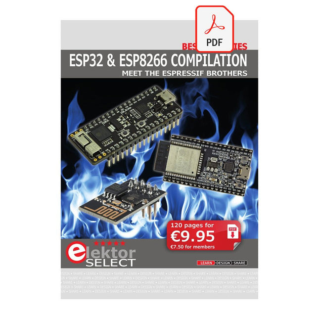
The ESP8266 from Espressif is a Wi-Fi microchip with full TCP/IP stack and microcontroller capability. It has made waves in the maker community with its low price.
But many developers were unhappy with ESP8266's high power consumption. The ESP32, equipped with a ULP (Ultra Low Power) coprocessor, offers a remedy for this.
This e-book features a number of projects featuring ESP32 & ESP8266 as well as an interview with the CEO of Espressif Teo Swee Ann.
Articles
ESP32 for Use in Industry 4.0 Equipment
Scrolling Message Display, 512 LEDs controlled over Wi-Fi via an ESP-12F
The Connected Greenhouse IoT demonstration project using MQTT and Node-RED
VFD-tube Clock with ESP32 with an accurate Internet-derived time
ESP32 Low Power
DCF77 Emulator with ESP8266
ESP8266 on the Elektor Android I/O Board
The Reason Behind the Hugely Popular ESP8266?
Wi-Fi Desktop Thermostat
Timers for the Wi-Fi Desktop Thermostat
PlatformIO, the Universal Programming Tool
Weather Display, Visualize current weather data on an LC display
GoNotify, a Flexible IoT Sensor Interface
ESP32 for Power Users
USB Programming Adaptor for ESP8266
Getting started with ESP32 and the Arduino IDE
MicroPython, Python for small systems
RGBDigit Clock
WLAN for Microcontrollers
Return of the Wi-Fi Controller Board
Compact and Self-contained WLAN
ÉLECTRICITÉ PHOTOVOLTAÏQUE = ÉLECTRICITÉ GRATUITE
Nous sommes désormais plus qu'heureux de poursuivre nos recherches sur notre propre autonomie et de veiller à ce que notre production électrique photovoltaïque soit appropriée ! D'abord on en rêve, puis vient l'étape du calcul : comparer le coût du kilowattheure d'origine du nucléaire (environnement à partir de centimes d'euro) et le calcul du kilowattheure d'origine photovoltaïque (l'environnement de 22 centimes de l'euro*), et nous saurons où en sont nos motivations d'écocitoyens.
Gérard Guihéneuf, l'auteur de ce nouveau livre, pense qu'il ne faut pas se contenter d'aligner chiffres et idées. La nouvelle approche du processus de création d'entreprise se base sur la compréhension et les dimensions des installations des bâtiments domestiques dans le domaine public en 2009 et sur l'actualité des techniques et pratiques de réponse aux questions qui se posent lors de l'électrification des le site isolé !
La conception de projets simples, comme un contexte domestique, et d'un commentaire électrique standard, comme un système d'énergie photovoltaïque, trois emplacements réguliers : un abri dans le jardin, un garage et un mobil-home.
L'économie est spectaculaire lorsqu'il s'agit de composants électroniques et d'assemblages de certains constituants essentiels, car les régulateurs de charge, les onduleurs et les panneaux solaires ne suffisent pas à l'entretien autonome du site. Si vous souhaitez en savoir plus sur l'électrification professionnelle de votre chantier, vous pouvez en savoir plus sur les dimensions des éléments constitutifs sans sacrifier l'efficacité !
Vous pouvez également utiliser la copie du Gerber et du Sprint Layout pour les circuits imprimés de la livrée.
*avec les batteries en cours de reconditionnement lors de la panne photovoltaïque en cours et dans les vingt-cinq
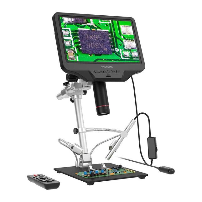
The Andonstar AD409 Pro-ES is a digital microscope with an extra-high stand that is also equipped with an endoscope. The microscope allows clear observation of the sides of components, the inside of pipes, etc., enabling 360° observation without dead angles. The microscope also has a remote control that allows you to easily switch between the following image modes: two-lens, microscope and endoscope.
Features
High-quality metal lens and focusing barrel
Professional HDMI digital microscope supports multiple output methods
Soldering Microscope with Pro Metal Stand
Unique UV filter design
8 Levels adjustable LED Lights
Convenient Wireless Remote Control
Professional Measurement Software
Specifications
Screen size
10.1 inch (25.7 cm)
Image sensor
4 MP
Video output
UHD 2880x2160 (24fps)FHD 1920x1080 (60fps/30fps)HD 1280x720 (120fps)
Video format
MP4
Magnification
Up to 300 times (27 inch HDMI monitor)
Photo resolution
Max. 12 MP (4032x3024)
Photo format
JPG
Focus range
Min. 5 cm
Frame Rate
Max. 120fps
Video interface
HDMI
Storage
microSD card (up to 64 GB)
PC support
Windows, PC software with measurement
Mobile phone, tablet terminal support
Support WiFi connection and measurement
Power source
5 V DC
Light source
2 LEDs with the stand
Endoscope
Yes
Stand size
18 x 20 x 32 cm
Included
1x Andonstar AD409 Pro-ES Digital Microscope
1x Endoscope
1x Metal stand with 2 LEDs
1x UV filter (already assembled in the lens)
1x IR remote
1x Switch cable
1x Power adapter
1x Wrench
2x Metal clips
1x HDMI cable
1x User manual
Downloads
Manual
Software
The FNIRSI HRM-10 is a portable, high-precision battery internal resistance and voltage tester. This device offers true four-wire measurement and is designed for both accuracy and ease of use. It automatically measures internal resistance and voltage values simultaneously, displaying the results on its HD color screen. Users have the option to manually adjust voltage and resistance ranges to suit their needs. The device also includes a sorting mode that automatically filters the good and bad batteries based on user-set thresholds. Additionally, it supports the storage of historical data and allows for exporting measurement records in table format.
Features
High Measurement Accuracy
Tabular Data Export
Auto-Evaluate Measurement Results
8 Threshold Settings
HD Color Screen
Folding Stand
1000 mAh Lithium Battery
Specifications
Voltage
Resistance
Measuring range
0-100 V (DC)
0-200 Ω
Accuracy
±0.5%
±0.5%
Gear
Automatic, 1 V, 10 V, 100 V
Automatic, 20 mΩ, 200 mΩ, 2 Ω, 20 Ω, 200 Ω
Instrument test signal frequency
1 Khz (AC)
Rechargeable
USB-C (5 V/1 A)
Built-in battery
1000 mAh lithium battery
User calibration
Yes
Sorting mode
Yes
History record
Yes
Recorded data export
Yes
Working environment
–10°C to +45°C, relative humidity <80%
Storage environment
–20°C to +80°C, relative humidity <80%
Dimensions
158.7 x 80.5 x 28.4 mm
Weight
225 g
Included
1x FNIRSI HRM-10 Internal Resistance Tester
1x Clip Test Line
1x USB-C data cable
1x Manual
Downloads
Manual
Firmware V0.3
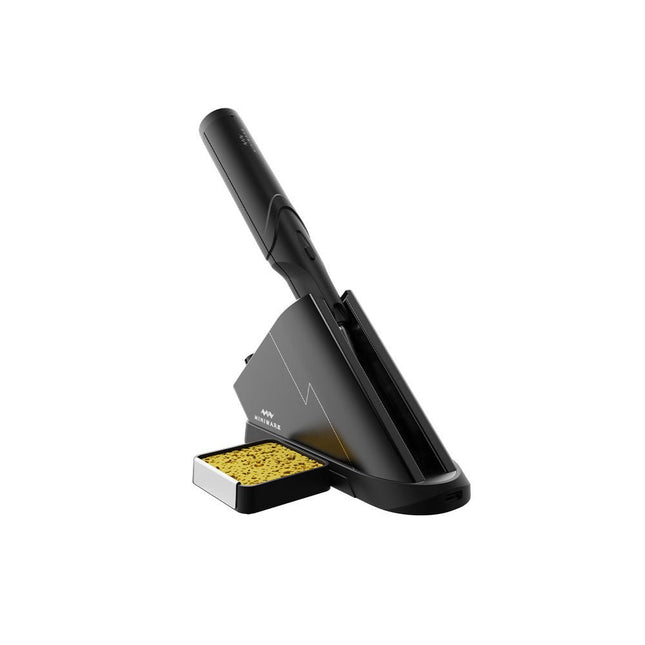
The Miniware Cordless Soldering Station TS1C (with integrated OLED screen and Bluetooth) is an intelligent soldering tool that heats up to 400°C in less than 20 seconds. Thanks to the built-in battery, the wireless soldering pen sits comfortably in the hand and is easy to use.
Features
New high-efficiency supercapacitor energy storage technology, 10,000-level charge and discharge times
Seperate design + true wireless, enjoy wireless soldering experience
BLE4.2 Bluetooth communication technology to realize remote control and setting
Standard PD2 20 V 45 W max power input, up to 36 W soldering power, can continuously solder more than 180 solder joints (0805) with a single full charge
Control station preheating to improve heating efficiency
3 expansion slots for accessories
Control Station
Standard PD2 20 V 45 W max power input, over current safety protection
128x64 pixel OLED screen, display soldering pen status in real time
Control station preheating, improve heating efficiency
Remote control and setting: temperature regulating, menu setting, viewing device info and status, etc.
Work as soldering stand and charging station
3 expansion slots for multiple expandable accessories like sponge slot
Soldering Pen
Built-in 750F high-efficiency energy storage supercapacitor, can be charged via control station (or via its USB Type-C interface in emergency cases)
36 W maximum heating power, can solder more than 180 solder joints (0805) continuously under a single full charge
Compatible with Miniware 3.5 mm audio interface soldering tips (TS80/80P soldering tip series)
Boost mode (holding the button on the pen)
Included
TS1C Soldering pen
TS1C Control station
Soldering tip (TS-B02)
Silicone cable
Sponge slot incl. sponge
Manual
PIC und AVR verstehen
In diesem Buch werden wir uns ausschließlich mit 8-Bit-Mikrocontrollern beschäftigen, und zwar mit Mikrocontrollern der 8-Bit-PIC- und der 8-Bit-AVR-Mikrocontroller-Linien. Bei der PIC-Familie handelt es sich dabei um PIC10, PIC12, PIC16 und PIC18; bei der AVR-Familie um ATtiny, ATmega und ATxmega. Die vorgestellten 8-Bit-Chips sind für sehr viele Anwendungen vollkommen ausreichend und preislich auch attraktiv.
Durch die Lektüre des Buches erhalten Sie ein fundiertes Wissen über die genannten 8-Bit-Mikrocontroller, über ihre Architektur, ihre Pinbelegungen und über ihre Programmierung.
Weil wir uns in diesem Buch mit den Grundlagen der Architektur der PICs und AVRs vertraut machen möchten, werden wir auch für alle PIC- und AVR-Anwendungen Assembler einsetzen, denn die Assembler-Sprache erlaubt es, die Technik im Detail kennenzulernen. Wenn man wirklich wissen möchte, was sich im Mikrocontroller abspielt, greift man zu Assembler. Damit hat man die beste Gelegenheit, sehr nah an den Kern zu kommen. Und wenn man schon einen Mikrocontroller-Typ kennengelernt und verstanden hat, ist es bei dem nächsten deutlich einfacher, auch wenn er von einem anderen Hersteller kommt. Bei anderen Programmiersprachen bleibt die Technik immer ziemlich tief versteckt.
Die Assembler-Beispiele sind so einfach gestaltet, dass sie jeder mit den im Buch aufgezeigten Programmiertechniken erstellen kann. Weil es sich um einfache Beispiele handelt, werden wir sie alle auf einer universellen Lochrasterplatine realisieren. Manche sind auch auf einem Experimentier-Breadboard umsetzbar.
Dieses Buch ist eine Einführung in das hochaktuelle Gebiet der Robotik. Dabei stehen praktische Anwendungsbeispiele im Vordergrund. Neben den technischen und mechanischen Grundlagen werden die elektronischen Komponenten und Module erläutert. Eine zentrale Rolle spielt dabei der Mikrocontroller.
Für Robotik-Anwendungen haben sich zwei Controller-Boards etabliert: der Arduino und der Raspberry Pi. Dem trägt dieses Buch Rechnung und beschreibt praktische Nachbauprojekte mit diesen beiden populären Boards.
Getreu der Philosophie des „Learning by Doing“ können sich auch ambitionierte, nichtprofessionelle Anwender mit dem Lernmaterial des Buches einen Überblick über den neuesten Stand der Robotertechnik und KI verschaffen. Für praktische Anwendungen können sowohl komplette Bausätze als auch einzelne Komponenten verwendet werden. Dabei wurde stets darauf geachtet, dass die Hardware möglichst universell einsetzbar ist.
The OWON SDS1102 is an affordable benchtop digital oscilloscope that combines solid performance with essential measurement features. This 2-channel oscilloscope offers a 100 MHz bandwidth, a 1 GS/s sampling rate, a 7-inch LCD display, and a 10 kpts memory depth, making it a practical choice for everyday electronics testing, troubleshooting, and education.
The SDS1102 features a simplified trigger system with level and edge triggering, making it easy to capture and analyze common signals. It is designed for applications that do not require deep memory or advanced trigger functions, offering a straightforward and cost-effective solution for basic signal analysis.
Features
Bandwidth: 100 MHz
2 channels
Sample rate: 1 GS/s
Ultra-thin body
7-inch high-res LCD
SCPI and LabVIEW supported
Specifications
Bandwidth
100 MHz
Horizontal Scale (s/div)
5 ns/div – 1000 s/div
Channel
2
Vertical Sensitivity
5 mV/div – 5 V/div (at input)
DC Gain Accuracy
3%
Vertical Resolution (A/D)
8 bits (2 channels simultaneously)
Input
Input Impedance
1 MΩ, 10 pF
Input Coupling
AC, DC, GND
Max Input Voltage
±400 V, CATI, CATII
Passive probes
х1; х10
Probe Attenuation Factor
х1; х10; х100; х1000
Trigger System
Trigger Mode
Auto, Normal, Single
Trigger Type
Edge, Video
Edge Trigger Source
CH1, CH2
Video Trigger
Sampling Type
Real-time
Sample Rate
1 GS/s
Equivalent Sample Rate
No
Wavelength
10K pts
Interpolation
sin(x)/x
Measurement and Mathematical Treatment System
Automatic Measurement
Vpp, Vavg, RMS, Frequency, Period, Vmax, Vmin, Vtop, Vbase, Width, Overshoot, Pre-shootRise time, Fall time, +Width, -Width, +Duty, -Duty, Delay A→B, Delay A→B, area, cycle area
Math Functions
Addition, Subtraction, Multiplication, Division, FFT
General Characteristics
Display type
7" color LCD
Display Resolution
800 x 480
Power
100-240 V, 45-440 Hz, <15 W
Dimensions
301 x 70 x 152 mm
Weight
1.1 kg
Included
1x OWON SDS1102 Oscilloscope
2x Oscilloscope probes
1x Probe adjust
1x Mains power cord
1x USB cable
1x CD-Rom
1x Quick guide
Downloads
Quick Guide
Manual
PC Software
SCPI Commands
Practical Projects and Programs
With Experimenting with Red Pitaya STEMlab Gen 2, Red Pitaya goes beyond a versatile board. It becomes a powerful laboratory instrument for precision measurement, analysis, and control.
From the fundamentals of electronic project development, monitoring, control, and design to testing, this book walks you step-by-step through everything you need to know to harness the full potential of Red Pitaya hardware and software.
The book presents real-time, FPGA-based projects that are developed on a PC using the Vivado environment, then transferred to the Red Pitaya for execution and testing.
You will learn about enhanced performance, expanded I/O capabilities, improved FPGA features, and advanced connectivity options that open up new frontiers for precision measurement, monitoring, and control in your embedded applications.
Inside the book you will discover:
A deep dive into Red Pitaya architecture and hardware design
Electronic experiments using Red Pitaya for measurement and monitoring
Hands-on projects using the Python programming language
Practical guidance for FPGA programming using Red Pitaya
Red Pitaya FPGA projects using the Verilog HDL under Vivado IDE
Practical design of electronic projects including measurement and testing
Step-by-step examples that bridge theory and real-world implementation
Whether you are designing your own electronic circuits, developing signal analysis tools, or creating real-time control or monitoring systems, this book provides you the knowledge and confidence you need to fully learn and customize the Red Pitaya platform.
A Practical Guide to AI, Python, and Hardware Projects
Welcome to your BeagleY-AI journey! This compact, powerful, and affordable single-board computer is perfect for developers and hobbyists. With its dedicated 4 TOPS AI co-processor and a 1.4 GHz Quad-core Cortex-A53 CPU, the BeagleY-AI is equipped to handle both AI applications and real-time I/O tasks. Powered by the Texas Instruments AM67A processor, it offers DSPs, a 3D graphics unit, and video accelerators.
Inside this handbook, you‘ll find over 50 hands-on projects that cover a wide range of topics—from basic circuits with LEDs and sensors to an AI-driven project. Each project is written in Python 3 and includes detailed explanations and full program listings to guide you. Whether you‘re a beginner or more advanced, you can follow these projects as they are or modify them to fit your own creative ideas.
Here’s a glimpse of some exciting projects included in this handbook:
Morse Code Exerciser with LED or BuzzerType a message and watch it come to life as an LED or buzzer translates your text into Morse code.
Ultrasonic Distance MeasurementUse an ultrasonic sensor to measure distances and display the result in real time.
Environmental Data Display & VisualizationCollect temperature, pressure, and humidity readings from the BME280 sensor, and display or plot them on a graphical interface.
SPI – Voltmeter with ADCLearn how to measure voltage using an external ADC and display the results on your BeagleY-AI.
GPS Coordinates DisplayTrack your location with a GPS module and view geographic coordinates on your screen.
BeagleY-AI and Raspberry Pi 4 CommunicationDiscover how to make your BeagleY-AI and Raspberry Pi communicate over a serial link and exchange data.
AI-Driven Object Detection with TensorFlow LiteSet up and run an object detection model using TensorFlow Lite on the BeagleY-AI platform, with complete hardware and software details provided.