Elektor GREEN en GOLD leden kunnen deze uitgave hier downloaden.
Nog geen lid? Klik hier om een lidmaatschap af te sluiten.
OBD2-sensordashboardOude meters vormden het startpunt van een zoektocht naar echte gegevens
OBD2: voeg een toerenteller en schakelindicator toe aan je autoRetro, maar uiterst nuttig
LiDAR- en Visiesensoren voor Robotica
Sensor+Test 2025 en PCIM 2025
Contactloze E-Veldmetingen (1)Een Trillende Membraan voor het Detecteren van Gelijkspanningen of Statische Elektrische Velden
Draadloze brievenbusmeldervan optische sensoren tot radar: enkele mogelijkheden
Elektor Mini-Wheelieeen zelfbalancerende robot
ZonnecellenVreemde onderdelen, de serie
Aan de slag met een moderne radarsensorStaat een nauwkeurige meting op uw radar?
Uit het leven gegrepenpapierfabriek
CybersecurityZware tijden voor hackers
Infographics: IoT en sensoren 2025
Bluetooth 6.0 brengt verbeterde toepassingen voor afstandsbepalingNieuwe versie biedt betere apparaatpositionerings- en -locatieservices
Draadloze communicatie verkennen met BeagleY-AI
Err-lectronicsCorrecties, updates en lezerspost
Alle begin......sluit het thema opamps af
Een krachtige AI-codeerassistentsneller ontwikkelen met Continue en Visual Studio Code
Zonne-laadregelaar met MPPT (2)Het schema
Ultrasone obstakeldetectoreen eenvoudig project om slechtzienden te helpen
2025: Een AI-odysseeHalfjaaroverzicht
Raspberry Pi Standalone MIDI-synthesizer (3)Het slimmer maken en een gebruikersinterface toevoegen
Meshtastic: een demonstratieprojectEen slim netwerk van LoRa-radio's
Analoge audio-frequentiegeneratorHoogwaardige sinusgenerator met instelbare frequentie
The Seeed Studio RF Explorer 3G Combo is a handheld digital spectrum analyzer and an affordable tool for working across a wide range of popular frequency bands. It is based on a highly integrated frequency synthesizer and a double-balanced mixer, providing high performance, compact dimensions, low power consumption, and excellent value.
Designed for both indoor and outdoor use, the RF Explorer 3G Combo can also be connected to a PC via a standard Mini-USB 2.0 connector for additional functionality.
This model combines a WSUB1G base unit with an RFEMWSUB3G expansion module, supplied fully assembled and tested. It features two SMA connectors and includes two antennas: a dual-band 144/430 MHz telescopic antenna for sub-GHz frequencies and a helical whip antenna for the 2.4 GHz band. Additional frequency-specific antennas may be required for optimal performance in certain supported frequency ranges.
This combination provides the wide frequency coverage of the WSUB3G module together with the high sensitivity and fast response of the WSUB1G unit in the commonly used sub-1 GHz frequency range.
Features
Pocket size and light weight
Solid aluminum metal case
Includes a transport EVA carry case for RF Explorer
Spectrum Analyzer mode with Peak Max and Hold, Normal, Overwrite and Averaging modes
Lifetime free firmware upgrades available, open to community requested features
High capacity Lipo for 16+ hours of continuous run, rechargeable by USB
Windows PC client Open Source
Can be extended with internal Expansion Modules for additional band and functionality
Wide band coverage to all popular RF frequencies, starting at 15 MHz and going up to 2.7 GHz. This includes very interesting frequency areas such as 2 m HAM radio, all VHF and UHF, FM radio, GPS, WiFi and WiMax, Bluetooth, etc.
Firmware: RF Explorer 3G Combo is delivered with upgraded firmware v1.09. Note some of the features and operation accuracy will be improved in upcoming free firmware revisions.
Specifications
Battery
Lithium Cells / Batteries contained in equipment UN3481 - PI967
Frequency band
15-2700 MHz
Frequency span
112 KHz - 600 MHz
Graphics LCD
128 x 64 pixels, great visibility outdoors
PC Windows client
Supports Windows (32 and 64 bits)
Backlight
For great indoor visibility
2 standard SMA 50 ohms connector,
One for Sub-GHz wideband Nagoya NA-773 telescopic antenna included and another 2.4 GHz one for 15-2700 MHz band with helical antenna included.
Amplitude resolution
0.5 dBm
Dynamic range
Left SMA port (WSUB1G)
-115 dBm to 0 dBm
Right SMA port (WSUB3G)
-110 dBm to -10 dBm
Absolute Max input power
Left SMA port (WSUB1G)
+5 dBm
Right SMA port (WSUB3G)
+30 dBm
Average noise level (typical)
-110 dBm
Frequency stability and accuracy (typical)
±10 ppm
Amplitude stability and accuracy (typical)
±6 dBm
Frequency resolution
1 KHz
Resolution bandwidth (RBW)
Automatic 3 KHz to 600 KHz
Weight
185 g
Dimensions
113 x 70 x 25 mm
Included
Seeed Studio RF Explorer 3G Combo Spectrum Analyzer
Nagoya NA-773 wideband telescopic antenna
2.4 GHz band antenna
EVA Case
Documentation
For more info and to get started with your RF Explorer, visit the start page.
For questions and support, please visit https://support.rf-explorer.com
The OWON XDM2041 is a low-cost, high-precision benchtop multimeter. The meter has a True RMS function to measure the AC voltage and current and it has a reading speed of up to 65 values per second. Also, the XDM2041 is equipped with functions such as measuring 2-wire and 4-wire resistance.
The XDM2041 is able to store data internally in the memory of the meter and display it on the 3.7" high-resolution LCD display. Up to 1000 points can be stored and the time interval can be varied from 15ms to 9999s. By means of the RS232 port on the back of the device, the meter can be programmed and controlled via SCPI.
Specifications
Measurement Range
Resolution
Accuracy ±(% of reading + LSB)
DC Voltage
50.000mV
0.001mV
0.1%+10
500.00mV
0.01mV
0.025%+5
5.0000V
0.0001V
0.025%+5
50.000V
0.001V
0.03%+5
500.00V
0.01V
0.1%+5
1000.0V
0.1V
0.1%+5
AC Voltage
500mv-750v
20Hz~45Hz
1%+30
45Hz~65Hz
0.5%+30
65Hz~1KHz
0.7%+30
DC Current
500uA
0.01uA
0.15%+20
5000uA
0.1uA
0.15%+10
50mA
0.001mA
0.15%+20
500mA
0.01mA
0.15%+10
5A
0.0001A
0.5%+10
10A
0.001A
0.5%+10
AC Current
500uA-500mA
20 Hz-1 kHz
0.5%+20
5A-10A
1.5%+20
Resistance
500Ω
0.01Ω
0.1%+10
5KΩ
0.0001KΩ
0.1%+5
50KΩ
0.001KΩ
0.1%+5
500KΩ
0.01KΩ
0.1%+5
5MΩ
0.0001MΩ
0.25%+5
50MΩ
0.001MΩ
0.1%+10
Four-wire resistance
500Ω
0.01Ω
0.1%+10
5KΩ
0.0001KΩ
0.1%+5
50KΩ
0.001KΩ
0.1%+5
Measurement Range
Resolution
Accuracy ±(% of reading + % of range)
Frequency
10.000Hz-60MHz
/
±(0.2%+8)
Capacitance
50nF-500uF
/
2.5%+5
5mF-50mF
5%+8
Diode
3.0000 V
0.0001V
/
Continuity
1000 Ω
0.1Ω
/
Temperature
K type,PT100
Display
55,000
Data-logging Function
Logging Duration
15ms-9999s
Logging Length
1,000 points
Included
1x OWON XDM2041 Multimeter
2x Multimeter leads
2x Alligator clips
1x Fuse
1x Manual
Downloads
User manual
Programming manual
PC software
The tinySA Ultra+ ZS-407 is a compact, handheld spectrum analyzer and signal generator. Covering 100 kHz to 7.3 GHz in Ultra mode, it lets you visualize and analyze RF signals from HF right through many modern wireless bands – and can even spot signals up to ~12 GHz thanks to harmonic tracking.
The intuitive 4-inch resistive touchscreen and rechargeable battery make it great for fieldwork, while features like a built-in signal generator, switchable bandpass filters, step attenuator, USB-PC control and auto-calibration add serious versatility.
Features
Screen size: 4 inch (480 x 320)
Spectrum Analyzer for 0.1-900 MHz or, with Ultra mode enabled up to 7.3 GHz, level calibrated up to 7.3 GHz. Can observe signals up to 12 GHz
Signal Generator with sine wave output between 0.1-900 MHz or square wave up to 6.3 GHz or RF test signal output up to 7.3 GHz when not used as Spectrum Analyzer.
Switchable resolution bandpass filters from 200 Hz to 850 kHz
Built-in 20 dB optional LNA
Color display showing max 450 points providing gapless covering up to the full frequency range.
MicroSD card slot for storing measurements, settings and screen captures.
Specifications (Spectrum Analyzer)
Input frequency range from 100 kHz to 900 MHz in normal mode and up to 7.3 GHz with ULTRA mode enabled
Input impedance 50 ohm when input attenuation set to 10 dB or more.
Selectable manual and automatic input attenuation between 0 dB and 31 dB in 1 dB steps when LNA not active
Maximum +/-5V DC input
Absolute maximum input level of +6 dBm with 0 dB internal attenuation
Absolute maximum short term peak input power of +20 dBm with 30 dB internal attenuation
Suggested maximum input power of +0 dBm with internal attenuation in automatic mode
For best measurements keep input power below -25 dBm
Input Intercept Point of third order modulation products (IIP3) of +15 dBm with 0 dB internal attenuation
1 dB compression point at -1 dBm with 0 dB internal attenuation
Power detector resolution of 0.5 dB and linearity versus frequency of ±2 dB below 5.3 GHz, ±5dB between 5.3 GHz and 6 GHz
Minimum burst length for correct level measurement at 850 kHz RBW in zero span mode of 50 microseconds
Absolute power level accuracy after power level calibration of ±2 dB
Built-in optional 20 dB LNA with Noise Figure of 5 dB up to 6 GHz
Lowest discernible signal without LNA at 30 MHz using a resolution bandwidth of 30 kHz of -102 dBm
Lowest discernible signal with LNA at 30 MHz using a resolution bandwidth of 200 Hz of -145 dBm
Frequency accuracy equal to the selected resolution bandwidth
Phase noise at 30 MHz of -108 dB/Hz at 100 kHz offset and -115 dB/Hz at 1MHz offset
Spur free dynamic range when using a 30 kHz resolution bandwidth of 70 dB
Resolution filters with a width of 0.2, 1, 3, 10, 30, 100, 300, 600 and 850 kHz
On screen resolution of 51, 101, 145, 290 or 450 measurement points.
Scanning speed of over 1000 points/second using largest resolution filters.
Automatic optimization of actual scanning points to ensure coverage of the whole scan range regardless of the chosen resolution bandwidth
Spur suppression option for assessing if certain signals are internally generated or actually present in the input signal
Headphone output for listening to the demodulated audio (AM only). Stereo connector with or without microphone, high impedance is louder, short protected
Specifications (Signal Generator)
Sine wave output with harmonics below -40 dB of fundamental from 100 kHz to 900 MHz
Output level selectable in 1 dB steps between -115 dBm and -19 dBm
Above 800 MHz choice of two output modes:
Cleanest signal mode: square wave, up to 6 GHz with coarse frequency steps and less accurate output level
Highest accuracy mode: reduced harmonics with possibly strong spurs up to 7.3 GHz with frequency resolution equal to below 800 MHz and fine output level steps
Level accuracy ±2 dB up to 800 MHz between -72 dBm and -19 dBm, less accuracy below -72 dBm, even less accuracy below -110 dBm
Output frequency resolution 57.2 Hz
Optional AM or FM modulation frequencies between 50 Hz and 5 kHz (AM) or 1 kHz (FM) or sweep over selectable frequency span
AM modulation depth between 10% and 100%
FM deviation between 1 kHz and 300 kHz
Optional output level sweep over maximum the entire output level range
Included
1x tinySA Ultra+ ZS407 Spectrum Analyzer
2x SMA connection cables
1x Barrel connector
1x Antenna with SMA connector
1x USB-C cable
1x microSD card (32 GB)
Downloads
Wiki
Hands-on in more than 50 projects
STM32 Nucleo family of processors are manufactured by STMicroelectronics. These are low-cost ARM microcontroller development boards. This book is about developing projects using the popular STM32CubeIDE software with the Nucleo-L476RG development board. In the early Chapters of the book the architecture of the Nucleo family is briefly described.
The book covers many projects using most features of the Nucleo-L476RG development board where the full software listings for the STM32CubeIDE are given for each project together with extensive descriptions. The projects range from simple flashing LEDs to more complex projects using modules, devices, and libraries such as GPIO, ADC, DAC, I²C, SPI, LCD, DMA, analogue inputs, power management, X-CUBE-MEMS1 library, DEBUGGING, and others. In addition, several projects are given using the popular Nucleo Expansion Boards. These Expansion Boards plug on top of the Nucleo development boards and provide sensors, relays, accelerometers, gyroscopes, Wi-Fi, and many others. Using an expansion board together with the X-CUBE-MEMS1 library simplifies the task of project development considerably.
All the projects in the book have been tested and are working. The following sub-headings are given for each project: Project Title, Description, Aim, Block Diagram, Circuit Diagram, and Program Listing for the STM32CubeIDE.
In this book you will learn about
STM32 microcontroller architecture;
the Nucleo-L476RG development board in projects using the STM32CubeIDE integrated software development tool;
external and internal interrupts and DMA;
DEBUG, a program developed using the STM32CubeIDE;
the MCU in Sleep, Stop, and in Standby modes;
Nucleo Expansion Boards with the Nucleo development boards.
What you need
a PC with Internet connection and a USB port;
STM32CubeIDE software (available at STMicroelectronics website free of charge)
the project source files, available from the book’s webpage hosted by Elektor;
Nucleo-L476RG development board;
simple electronic devices such as LEDs, temperature sensor, I²C and SPI chips, and a few more;
Nucleo Expansion Boards (optional).
With the JOY-iT PS1440-C-Pro, you get a programmable laboratory power supply that delivers DC voltages ranging from 0.01 to 60 V and DC currents from 0.01 to 24 A at the voltage output.
The intuitive control panel allows you to program, store, and recall up to 9 different DC voltage settings. You can also configure individual protection and limiting functions—such as overvoltage protection. All settings are easily adjusted via the keypad and/or rotary control and are clearly shown on the high-resolution 2.4" color display.
For enhanced connectivity, the PS1440-C-Pro includes an RS485 interface for robust, long-distance communication. This makes it ideal for complex setups where signal stability, noise immunity, and reliable data transfer are critical. The included connector ensures a secure connection, improving the overall reliability and performance of your laboratory equipment setup.
Features
Complete device ready for immediate use
RS485 interface
Battery charging function
Values can be entered conveniently via keypad
Over current & over voltage protection adjustable
Integrated RTC, NTC temperature sensor
Included detailed documentation in English, German & French
Specifications
Input voltage
230 V
Output voltage
060 V
Output current
0-24 A
Output power
0-1440 W
Input voltage accuracy
±1% +5 digits
Output voltage accuracy
±0.3% +3 digits
Output current accuracy
±0.5% +5 digits
Battery voltage
±0.5% +3 digits
Input voltage measurement resolution
0.01 V
Output voltage measurement resolution
0.01 V
Current measurement resolution
0.01 V
Battery voltage measurement resolution
0.01 V
Response time in constant voltage mode
2 ms @ 0.1-5 A
Load regulation in constant voltage mode
±0.1% +2 digits
Load regulation in constant current mode
±0.1% +3 digits
Measuring range electric charge
0-9999.99 Ah
Measuring range energy
0-9999.99 Wh
Statistical errors in electric charge & energy
±2%
Output ripple
100 mV VPP @ 12 V150 mV VPP @ 24 V
Sensor temperature detection range
−10~100°C (0-200°F)
Sensor temperature detection accuracy
±3°C (±6°F)
Working mode
Step-down operation
Screen brightness setting
Level 0-5, 6 levels in total
Permissible working temperature
−10~40°C (0-104°F)
Dimensions
170 x 93 x 340 mm
Included
JOY-iT PS1440-C Power Supply
2-pin connector for RS485 interface
Power cord
Manual
Downloads
Datasheet
MODBUS Protocol
PC Software
Driver for Windows
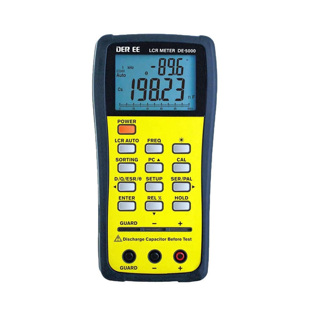
The DE-5000 is a smart, high-accurate, flexible and easy-to-use portable LCR meter. It features automatic LCR check, 4-wire Kelvin measurement, backlit display with 19999/1999 counts, multiple measurement modes and selectable test frequencies (100 Hz, 120 Hz, 1 kHz, 10 kHz or 100 kHz). The DE-5000 LCR meter is a practical helper for engineers or technicians.
Features
Auto L.C.R. check
Ls/Lp/Cs/Cp/Rs/Rp/DCR with D/Q/θ/ESR measurement
4-wire Kelvin measurement
20,000 / 2,000 counts display
Backlight
Relative mode
Series / Parallel modes
Components sorting function
Low battery indication
Auto power off
Specifications
Test frequency
100 Hz / 120 Hz / 1 kHz / 10 kHz / 100 kHz
Resistance range
20.000 Ω – 200.0 MΩ
DCR range
200.00 Ω – 200.0 MΩ
Capacitance range
200.00 pF – 20.00 mF
Inductance range
20.000 µH – 2.000 KH
Display (backlit LCD)
19999 / 1999 counts
Selectable tolerance
±0.25%, ±0.5%, ±1%, ±2%, ±5%, ±10%, ±20%
Power supply
9 V battery
Dimensions
188 x 95 x 52 mm
Weight
350 g (excluding battery)
Included
DE-5000 LCR meter
Alligator test lead case (TL-21)
AC/DC adaptor
Guard line (TL-23)
TL-22 SMD tweezers
9 V battery
Carrying case
Manual
Downloads
Datasheet
MOTOREN AANSTUREN MET H-BRUGGENeen inleiding tot gelijkstroom-, stappen- en borstelloze motoren
HET ELEKTOR LAB-TEAMonze aanpak, onze tools – en meer...
RASPBERRY PI ALS KVM-AFSTANDSBEDIENINGsoftwaretest Pi-KVM
IQAUDIO CODEC ZEROgeluidskaart voor de Raspberry Pi-familie
WAT WE KUNNEN LEREN VAN HET PIKVM-PROJECTeen vraaggesprek met Maxim Devaev
AUTONOOM RIJDEN MET 2D-LIDARESP32 Pico interpreteert gegevens van de lidar-module DE RASPBERRY PI ZERO 2 W GAAT QUAD-CORE NOTITIES BIJ VAN HET WORLD ETHICAL ELECTRONICS FORUM 2021
MOTORBESTURINGhoe de complexiteit van motorbesturing wordt gereduceerd
GROTE ELEKTROMOTORENbasisprincipes en nuttige informatie AAN DE SLAG MET DE ESP32-C3 RISC-V MCU
BESCHERM UZELF EN ANDEREN!DHZ-hoofdschakelaar voor uw werkbank
GUI'S MAKEN MET PYTHON (DEEL 2)Spionnennaamkiezer
PRODUCTRONICA FAST FORWARD 2021: DE WINNAARSspannende technologieën en creatieve engineeringoplossingen
VEELZIJDIGE SERVOTESTERcontroleer het gedrag, ook zonder datasheet
MODBUS VIA WLANdeel 2: software voor de Modbus TCP WLAN-module
KENNISMAKING MET NEURONEN IN NEURALE NETWERKENdeel 3: neuronen in de praktijk
IN EEN OPEN SOURCE-PROCESSORvoorbeeldhoofdstuk: vergelijking van Lattice- en Xilinx-FPGA’s
ALLE BEGIN......is nog niet klaar met de spoel
PROJECT 2.0correcties, updates en brieven van lezers
KLEUR NAAR GELUIDeen kleursensor via I2C uitlezen
BATTLAB-ONEmeet en optimaliseer de gebruiksduur van IoT-accu’s
EENVOUDIGE AARDLEKTESTERisolatietest voor lichtnetinstallaties
ARMOEDE EN ELEKTRONICAhet streven naar duurzame ontwikkeling
HEXADOKUpuzzelen voor elektronici
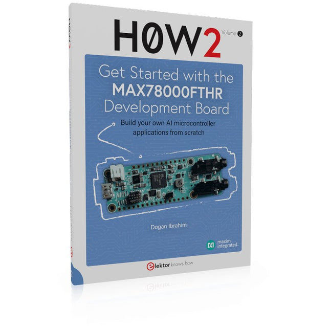
Build your own AI microcontroller applications from scratch
The MAX78000FTHR from Maxim Integrated is a small development board based on the MAX78000 MCU. The main usage of this board is in artificial intelligence applications (AI) which generally require large amounts of processing power and memory. It marries an Arm Cortex-M4 processor with a floating-point unit (FPU), convolutional neural network (CNN) accelerator, and RISC-V core into a single device. It is designed for ultra-low power consumption, making it ideal for many portable AI-based applications.
This book is project-based and aims to teach the basic features of the MAX78000FTHR. It demonstrates how it can be used in various classical and AI-based projects. Each project is described in detail and complete program listings are provided. Readers should be able to use the projects as they are, or modify them to suit their applications. This book covers the following features of the MAX78000FTHR microcontroller development board:
Onboard LEDs and buttons
External LEDs and buttons
Using analog-to-digital converters
I²C projects
SPI projects
UART projects
External interrupts and timer interrupts
Using the onboard microphone
Using the onboard camera
Convolutional Neural Network
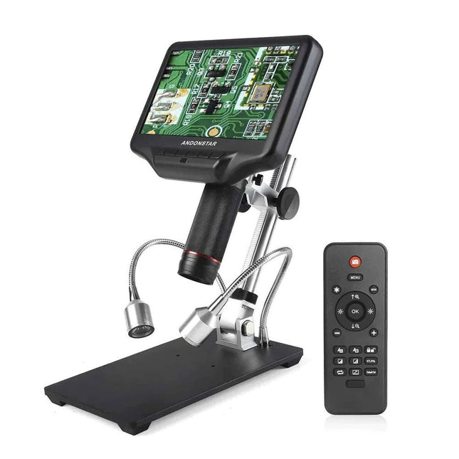
Examine your circuits with high precision and solder even the smallest SMDs and elements without any hassle.
Features
Multifunctional HDMI Digital Microscope features Full HD, comfortable headroom, improved ergonomy, multiple output signals with different resolutions.
Tilt angle of the wide LCD monitor is adjustable.
Comes with remote control.
Can be used as stand-alone.
Specifications
Screen size
7 inch (17.8 cm)
Image sensor
4 MP
Video output
UHD 2880x2160 (24fps)FHD 1920x1080 (60fps/30fps)HD 1280x720 (120fps)
Video format
MP4
Magnification
Up to 270 times (27 inch HDMI monitor)
Photo resolution
Max. 12 MP (4032x3024)
Photo format
JPG
Focus range
Min. 5 cm
Frame rate
Max. 120fps (under 600 Lux Brightness & HDP120)
Video interface
HDMI
Storage
microSD card (up to 32 GB)
Power source
5 V DC
Light source
2 LEDs with the stand
Stand size
20 x 12 x 19 cm
Included
1x Andonstar AD407 Digital Microscope
1x Metal stand with 2 LEDs
1x Optical bracket
1x UV filter
1x IR remote
1x Switch cable
1x Power adapter
1x HDMI cable
2x Screws
1x Screwdriver
1x User manual
Downloads
Manual
Model Comparison
AD407
AD407 Pro
AD409
AD409 Pro-ES
Screen size
7 inch (17.8 cm)
7 inch (17.8 cm)
10.1 inch (25.7 cm)
10.1 inch (25.7 cm)
Image sensor
4 MP
4 MP
4 MP
4 MP
Video output
2160p
2160p
2160p
2160p
Interfaces
HDMI
HDMI
USB, HDMI, WiFi
USB, HDMI, WiFi
Video format
MP4
MP4
MP4
MP4
Magnification
Up to 270x
Up to 270x
Up to 300x
Up to 300x
Photo resolution
Max. 4032x3024
Max. 4032x3024
Max. 4032x3024
Max. 4032x3024
Photo format
JPG
JPG
JPG
JPG
Focus distance
Min. 5 cm
Min. 5 cm
Min. 5 cm
Min. 5 cm
Frame rate
Max. 120f/s
Max. 120f/s
Max. 120f/s
Max. 120f/s
Storage
microSD card
microSD card
microSD card
microSD card
PC support
No
No
Windows
Windows
Mobile connection
No
No
WiFi + Measurement
WiFi + Measurement
Power source
5 V DC
5 V DC
5 V DC
5 V DC
Light source
2 LEDs with the stand
2 LEDs with the stand
2 LEDs with the stand
2 LEDs with the stand
Endoscope
No
No
No
Yes
Stand size
20 x 12 x 19 cm
20 x 18 x 32 cm
18 x 20 x 30 cm
18 x 20 x 32 cm
Weight
1.6 kg
2.1 kg
2.2 kg
2.5 kg
The FNIRSI HT-P1B Pro is a compact mini hot plate designed for PCB soldering, desoldering, and SMD rework. With up to 150 W of heating power, precise PID temperature control, and an adjustable temperature range of 100°C to 350°C, it delivers fast and stable heating for electronics projects.
The 50 x 50 mm heating surface is ideal for small PCBs and electronic components. Two operating modes – constant temperature heating and simulated reflow soldering – provide flexibility for different applications. A 1.44-inch color display, three temperature presets, and built-in safety features ensure convenient operation.
With DC and USB-C PD 3.1 support, a compact design, and an included 100 W USB-C charger, the HT-P1B Pro is a practical tool for makers, electronics enthusiasts, and repair professionals.
Features
Up to 150 W Heating Power: Fast heating with adjustable power settings from 30 W to 150 W.
Precise PID Temperature Control: Adjustable range from 100°C to 350°C with ±3°C temperature stability.
Dual Operating Modes: Constant temperature heating and simulated reflow soldering.
50 × 50 mm Heating Surface: Ideal for small PCBs, SMD soldering, and component rework.
Flexible Power Input: DC 12-28 V (up to 150 W) and USB-C PD 3.1 (up to 140 W).
Three Temperature Presets: Quick access to frequently used temperature settings.
1.44-inch Color Display: Shows temperature, voltage, power, heating time, and operating status.
Built-in Safety Features: Over-temperature, low-voltage, prolonged-heating, and tilt protection.
Specifications
Power Input
DC 12-28 V / USB-C PD
Power Range
30-150 W
Standby Power
1.6 W
Temperature Range
100-350°C (212-662°F)
Temperature Stability
±3°C
Heating Area
50 x 50 mm
Display
1.44" Color Screen
Tilt Detection
20°-50°
Protocol
PD 3.1
Dimensions
68.8 x 81.8 x 44.5 mm
Weight
157 g
Included
1x FNIRSI HT-P1B Preheating Station
1x FNIRSI 100 W PD GaN Charger (EU)
1x FNIRSI 100 W USB-C Fast-charging Cable
1x Heat-Resistant Silicone Cover
1x Storage Case
1x Manual
Downloads
Manual
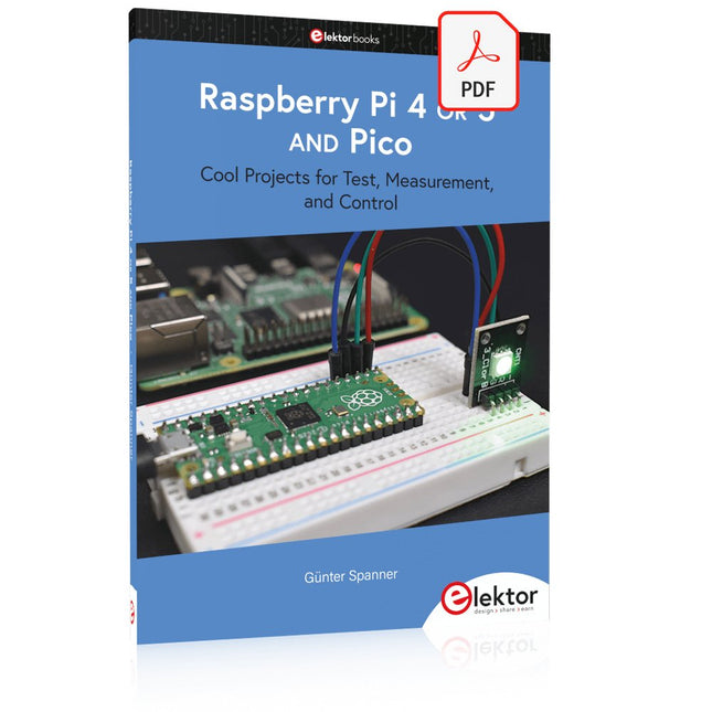
Cool Projects for Test, Measurement, and Control
The Raspberry Pi has dominated the maker scene for many years. Freely accessible I/O pins have made it one of the most popular processor boards of all time. However, the classic Raspberry Pi has no analog inputs. Direct measurement of analog values is therefore not possible. Consequently, photodiodes, NTCs, Hall sensors, etc. cannot be read directly. In addition, the pins are connected directly to the exposed contacts, i.e. without a driver or protection circuit. This can quickly destroy the central controller and thus the entire Raspberry Pi.
These problems can be elegantly solved with the Pico. As a front-end, it can easily handle a wide range of measurement tasks. In addition, the Pico is much cheaper than a classic Raspberry Pi 4 or 5. If a faulty circuit leads to the destruction of the Pico, this is relatively easy to handle. This makes the combination of a classic Raspberry Pi 4 or 5 and the Pico an ideal pair.
The book introduces the broad and highly topical field of modern controller technology using the combined force of a Raspberry Pi 4 or 5 and a Raspberry Pi Pico. In addition to a detailed introduction to the operation and functionality of the controller boards themselves, the book also focuses on data acquisition and processing with digital processors. Especially the combination of both systems offers a wide range of interesting possibilities.
Some practical projects from the contents:
USB between Raspberry Pi 4 or 5 and Pico
I²C Communication and Pico as an I²C device
Voltmeter and Computer Thermometer
Pico W as a Web Server and WLAN Scanner
Frequency Meters and Generators
OLED Displays on Raspberry Pi 4 or 5 and Pico
Energy Saving Monitor
Which Astronauts are in Orbit?
Mini Monitor for Current Bitcoin Exchange Rate