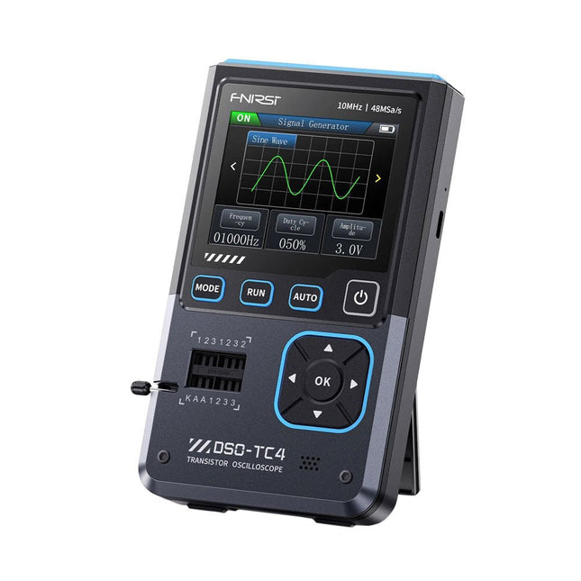
The FNIRDSI DSO-TC4 is a multifunctional transistor oscilloscope that is both comprehensive and practical. It is designed for use in maintenance and R&D applications, integrating an oscilloscope, transistor tester, and signal generator into a single device.
Features
Equipped with a 2.8-inch TFT color screen for a clear and intuitive display
Built-in high-capacity rechargeable lithium battery (1500 mAh) with a standby time of up to 4 hours
Compact and lightweight, ideal for mobile use
Specifications
Oscilloscope
Analog Bandwidth
10 MHz
Real-Time Sampling Rate
48 MSa/s
Input Impedance
1 MΩ
Coupling Mode
AC/DC
Test Voltage Range
1:1 Probe: 80 Vpp (+40 V)
10:1 Probe: 800 Vpp (+400 V)
Vertical Sensitivity
10 mV/div~10 V/div (X1 range)
Vertical Displacement
Adjustable with indication
Time Base Range
50ns~20s
Trigger Mode
Auto/Normal/Single
Trigger Type
Rising edge, Falling edge
Trigger Level
Adjustable with indication
Waveform Freeze
Yes (HOLD function)
Automatic Measurement
Max, Min, Avg, RMS, Vpp, Frequency, Cycle, Duty Cycle
Component Tester
Transistor
Amplification factor "hfe"; Base-Emitter voltage "Ube", Ic/Ie, Collector-Emitter reverse leakage current "Iceo", Ices, Forward voltage drop of protection diode "Uf"
Diode
Forward voltage drop <5 V (Forward voltage drop, Junction capacitance, Reverse leakage current)
Zener Diode
0.01~32 V
Reverse Breakdown Voltage (K-A-A Test Area)
Field-Effect Transistor (FET)
JFET: Gate capacitance "Cg", Drain current Id under "Vgs", Forward voltage drop of protection diode "Uf"
IGBT: Drain current Id under Vgs, Forward voltage drop of protection diode Uf
MIOSTET: Threshold voltage "Vt", Gate capacitance "Cg", Drain-Source resistance "Rds", Forward voltage drop of protection diode "Uf"
Unidirectional SCR
Trigger voltage <5V, Gate level (Gate voltage)
Bidirectional SCR
Trigger current <6mA (Gate voltage)
Capacitor
25pF~100mF, Capacitance value, Loss factor "Vloss"
Resistor
0.01Ω~50MΩ
Inductor
10μH~1000μH, DC resistance
DS18B20
Temperature sensor, Pins: GND, DQ, VDD
DHT11
Temperature and humidity sensor, Pins: VDD, DATA, GND
Signal Generator
Output Waveform
Supports 13 waveform outputs
Waveform Frequency
0-50 KHz
Square Wave Duty Cycle
0-100%
Waveform Amplitude
0.1-3.0 V
General
Display
2.8-inch TFT color screen
Backlight
Brightness adjustable
Power Supply
USB-C (5 V/1 A)
Battery
3.7 V/1500 mAh
Languages
English, German, Spanish, Portuguese, Russian, Chinese, Japanese, Korean
Dimensions
90 x 142 x 27.5 mm
Weight
186 g
Included
1x FNIRSI DSO-TC4 (3-in-1) Oscilloscope (10 MHz)
1x P6100 Oscilloscope probes (10X)
1x Alligator clip probe
3x Test hooks
1x Adapter
1x USB-C charging cable
1x Manual
Downloads
Manual
Firmware V0.0.7 (+V1.0.9)
The FNIRSI TMP-610S is a compact 3-in-1 test instrument combining a True RMS multimeter, 10 MHz oscilloscope, and 50 kHz DDS signal generator. It is designed for electronics troubleshooting, circuit testing, and development in the lab or on the go.
The multimeter offers 60,000-count resolution and supports voltage, current, resistance, capacitance, frequency, temperature, diode, and continuity measurements. The integrated oscilloscope provides real-time waveform analysis at up to 48 MSa/s, while the signal generator supports 13 waveform types with adjustable frequency, amplitude, and duty cycle.
A 3.5-inch IPS touchscreen, smart auto-scan, Bluetooth connectivity for DMM functions, waveform storage, USB export, and a 3,000 mAh rechargeable battery make the TMP-610S a versatile all-in-one tool for electronics professionals and enthusiasts.
Features
3-in-1 Design: DMM + Oscilloscope + Signal Generator
60,000-Count True RMS High-Precision Measurement
10 MHz Oscilloscope with 48 MSa/s Sampling Rate
Bluetooth App Sync (Multimeter Function Only)
3.5-inch Smart Touchscreen with Multiple Display Modes
50 kHz DDS Signal Generator with 13 Waveforms
Built-in Fuse for Easy Replacement
Specifications
Multimeter
Function
Range
Accuracy
DC voltage
600mV/6V/60V/600V/1000V
±(0.03%+5d)
AC voltage
600mV/6V/60V /600V/750V
±(0.3%+15d)
DC current
600uA/6000uA/60mA/600mA
±(0.15%+5d)
6A/10A
±(0.2%+5d)
AC current
600uA/6000uA/60mA/600mA
±(0.5%+15d)
6A/10A
±(0.75%+15d)
Resistance
600Ω/6KΩ/60KΩ/600KΩ/6MΩ
±(0.1%+5d)
60MΩ
±(0.2%+10d)
Capacitance
60nF/600nF/6uF/60uF
±(2.5%+30d)
600uF/6mF/60mF
±(3.5%+30d
Frequency
10 Hz~60 MHz
±(0.01%+5d)
Temperature
-40℃~1000℃
±(1.0%+5℃)
Continuity
0Ω~1KΩ
±(0.2%+5d)
Diode
0V~3.0V, 0Ω~1 Ω
±(1%+5d)
AC frequency response
10KHz
/
Oscilloscope
Real-time Sampling Rate
48 MSa/s
Analog Bandwidth
10 MHz
Input Impedance
1MΩ
Coupling Mode
AC/DC
Test Voltage Range
1:1 Probe - 80Vpp (±40V)
10:1 Probe - 800Vpp (±400V)
Vertical Sensitivity
10mV/div~10V/div
Vertical Displacement
Adjustable with indication
Horizontal Time Base Range
50 ns ~ 20 s
Trigger Mode
Auto, Normal, Single
Trigger Type
Rising, Falling, 50%
Trigger Level
Adjustable with indication
Measurement Parameters
Freq, Period, +Duty, ‒Duty, +Width, ‒Width, Max, Min, P‒P, Amp, RMS, Avg
Persistence
Off / 500ms / 1s / ∞
Cursor Measurement
Yes
Waveform Screenshot Saving
Yes
Signal Generator
Output Waveform
Supports 13 waveform types
Frequency
0~50kHz
Amplitude
0.0V~3.0V
Duty Cycle
0~100%, adjustable for Square and Sawtooth waves
Included
1x FNIRSI TMP-610S Multimeter + Oscilloscope + Signal Generator
1x P6100 Probe
1x Adapter
2x Alligator Clips
2x Multimeter Probes
Probe Accessories
1x Storage Bag
1x USB-C Cable
1x Manual
Downloads
Manual
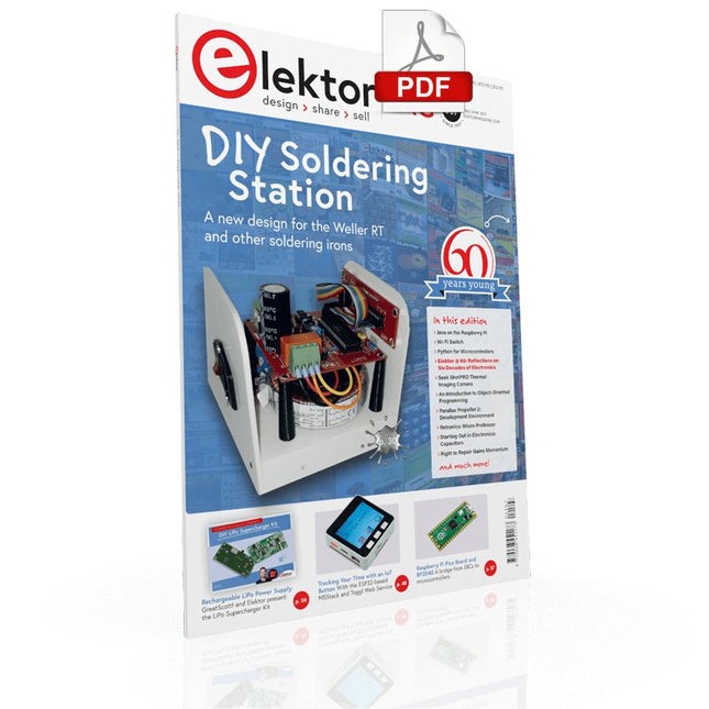
DIY LiPo Supercharger KitFrom Handcrafted to Mass Market
Elektor @ 60Reflections on Six Decades of Electronics
Siglent Bench Multimeter SDM3045X
DC Current-Sense ClampHall Sensor + Ferrite Core + Arduino
Soldering Station 2021Easy to build!
Hands On the Parallax Propeller 2Part 2: The Development Environment and Code
Wi-Fi for LoRa SwitchIntegrated in Home Assistant with ESPHome
Do Not Fear the Cellular Module!
Tracking Time with ESP32 and TogglWorking with the M5Stack
Get to Know the Raspberry Pi Pico Board and RP2040
MicroPython for MicrocontrollersSmall-Format Screens
12-to-200-V DC/DC Converter for Valve Amplifiers
Heat SeekerThe Seek Shot Pro Thermal Imaging Camera
Object-Oriented Programming: A Short Primer Using C++
HomeLab ToursHome Lab and an Analogue Synthesiser by Kurt Diedrich
Java on the Raspberry PiPart 1: GPIOs
DIP SwitchesPeculiar Parts, the series
Project 2.0Corrections, Updates and Readers’ Letters
Whose Product Is It Anyway?Right to Repair Gains Momentum
From Life's ExperienceThe Great Book of Blunders
Micro-ProfessorLearning Assembly Language on a Z80
Starting out in ElectronicsEasier Than Imagined! Even When It Is About Capacitors
HexadokuThe Original Elektorized Sudoku
The FNIRSI GC-03 is a multifunctional radiation detector designed for professional nuclear radiation measurement in everyday environments such as the home, office, car, and outdoors. Equipped with a 2.4-inch high-definition color display, it provides real-time monitoring of nuclear radiation as well as electric and magnetic field strength. For added safety, the device features three alarm modes: audible alert, vibration, and visual light warning.
Features
3-in-1 Detection: Monitors electric, magnetic, and nuclear radiation with one device.
High-Precision GM Tube: Accurately detects gamma, X-rays, and hard beta radiation with low power consumption.
Real-Time Curve + 50 Alarm Records: Tracks radiation trends and stores alarm history for easy review.
Custom Triple Alarms: Supports visual, audible, and vibration alerts with adjustable thresholds.
Long Battery Life: 1500 mAh battery for extended and reliable field use.
Specifications
Nuclear Radiation
Range: 0.01μSv/h-999.99μSv/h
Accuracy: 0.01μSv/h
Electric Field
Range: 1V/m-1999V/m
Accuracy: 1V/m
Magnetic Field
Range: 0.01μT-99.99μT
Accuracy: 0.01μT
Radiation Power
0.2-1000mW/m²
Detection Radiation Type
Ionizing radiation (gamma rays, etc.)
Detector
Energy compensation GM tube (Geiger counter tube)
Dose Current Rate
0.00-10000μSv/h (10mSv/h)
Cumulative Dose Equivalent
0.00μSv-500.0mSv
Energy Range
48keV-1.5MeV ≤ ±30% (for 137Cs-)
Sensitivity
80CPM/μSv
Dose Unit
μSv/h, uGy/h, mR/h, CPS, CPM
Alarm Mode
Light, vibration, sound
Display
2.4-inch color screen
Backlight
Brightness Adjustable
Power Supply
USB-C (5 V/1 A)
Battery
1500 mAh
Languages
English, Chinese
Dimensions
138 x 63 x 32 mm
Weight
141 g
Included
1x FNIRSI GC-03 Radiation Detector
1x USB cable
1x Manual
Downloads
Manual
Firmware v1.0.4
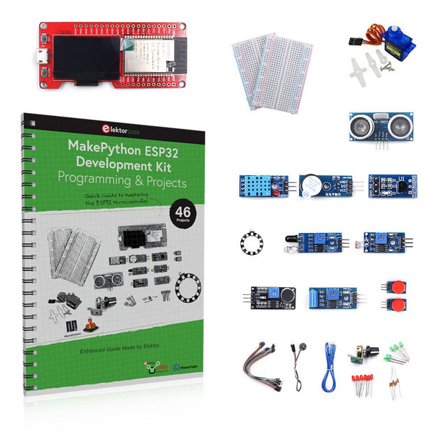
Learn how to use the ESP32 Microcontroller and MicroPython programming in your future projects!
The project book, written by well-known Elektor author Dogan Ibrahim, holds many software- and hardware-based projects especially developed for the MakePython ESP32 Development Kit. The kit comes with several LEDs, sensors, and actuators. The kit will help you acquire the basic knowledge to create IoT projects.
The book’s fully evaluated projects feature all the supplied components. Each project includes a block diagram, a circuit diagram, a full program listing, and a complete program description.
Included in the kit
1x MakePython ESP32 development board with LCD
1x Ultrasonic ranging module
1x Temperature and humidity sensor
1x Buzzer module
1x DS18B20 module
1x Infrared module
1x Potentiometer
1x WS2812 module
1x Sound sensor
1x Vibration sensor
1x Photosensitive resistance module
1x Pulse sensor
1x Servo motor
1x USB cable
2x Button
2x Breadboard
45x Jumper wire
10x Resistor 330R
10x LED (Red)
10x LED (Green)
1x Project book (206 pages)
46 Projects in the Book
LED Projects
Blinking LED
Flashing SOS
Blinking LED – using a timer
Alternately flashing LEDs
Button control
Changing the LED flashing rate using pushbutton interrupts
Chasing-LEDs
Binary-counting LEDs
Christmas lights (random-flashing 8 LEDs)
Electronic dice
Lucky day of the week
Pulsewidth Modulation (PWM) Projects
Generate a 1000-Hz PWM waveform with 50% duty cycle
LED brightness control
Measuring the frequency and duty cycle of a PWM waveform
Melody maker
Simple electronic organ
Servo motor control
Servo motor DS18B20 thermometer
Analog To Digital Converter (ADC) Projects
Voltmeter
Plotting the analog input voltage
ESP32 internal temperature sensor
Ohmmeter
Photosensitive resistance module
Digital To Analog Converter (DAC) Projects
Generating fixed voltages
Generating a sawtooth-wave signal
Generating a triangular-wave signal
Arbitrary periodic waveform
Generating a sinewave signal
Generating accurate sinewave signal using timer interrupts
Using The OLED Display
Seconds counter
Event counter
DS18B20 OLED based digital thermometer
ON-OFF temperature controller
Measuring the temperature and humidity
Ultrasonic distance measurement
Height of a person (stadiometer)
Heart rate (pulse) measurement
Other Sensors Supplied with the Kit
Theft alarm
Sound-activated light
Infrared obstacle avoidance with buzzer
WS2812 RGB LED ring
Timestamping temperature and humidity readings
Network Programming
Wi-Fi scanner
Remote control from the Internet browser (using a smartphone or PC) – Web Server
Storing temperature and humidity data in the Cloud
Low-Power Operation
Using a timer to wake up the processor
Over 45 Builds for the Legendary 555 Chip (and the 556, 558)
The 555 timer IC, originally introduced by the Signetics Corporation around 1971, is sure to rank high among the most popular analog integrated circuits ever produced. Originally called the IC Time Machine, this chip has been used in many timer-related projects by countless people over decades.
This book is all about designing projects based on the 555 timer IC. Over 45 fully tested and documented projects are presented. All projects have been fully tested by the author by constructing them individually on a breadboard. You are not expected to have any programming experiences for constructing or using the projects given in the book. However, it’s definitely useful to have some knowledge of basic electronics and the use of a breadboard for constructing and testing electronic circuits.
Some of the projects in the book are:
Alternately Flashing Two LEDs
Changing LED Flashing Rate
Touch Sensor On/Off Switch
Switch On/Off Delay
Light-Dependent Sound
Dark/Light Switch
Tone Burst Generator
Long Duration Timer
Chasing LEDs
LED Roulette Game
Traffic Lights
Continuity Tester
Electronic Lock
Switch Contact Debouncing
Toy Electronic Organ
Multiple Sensor Alarm System
Metronome
Voltage Multipliers
Electronic Dice
7-Segment Display Counter
Motor Control
7-Segment Display Dice
Electronic Siren
Various Other Projects
The projects given in the book can be modified or expanded by you for your very own applications. Electronic engineering students, people engaged in designing small electronic circuits, and electronic hobbyists should find the projects in the book instructive, fun, interesting, and useful.
This bundle includes the Red Pitaya STEMlab 125-14 PRO Gen 2 Starter Kit and the new book "Experimenting with Red Pitaya STEMlab Gen 2".
The Red Pitaya STEMlab 125-14 PRO Gen 2 Starter Kit is a powerful and flexible platform for signal processing, data acquisition, and electronic measurement applications. Designed for engineers, developers, researchers, and educators, this kit provides everything required to start building advanced measurement and control systems.
At the core of the kit is the STEMlab 125-14 PRO Gen 2 board, an upgraded and ultra-lightweight development platform. Powered by the Xilinx Zynq-7010 SoC with 512 MB of RAM, it combines FPGA programmability with ARM processing power to enable high-performance instrumentation and custom signal-processing solutions.
The board offers 14-bit ADC and DAC resolution, a 125 MS/s sampling rate, an input range of ±20 V, and up to 60 MHz bandwidth. Its improved low-noise analog front-end, USB-C connectivity, and compact design make it suitable for demanding applications such as RF development, radar systems, photonics research, software-defined radio (SDR), and industrial automation.
The Starter Kit includes all essential accessories for immediate use: a microSD card with preinstalled operating system, power supply, Ethernet cable for remote access, two 100 MHz oscilloscope probes, and SMA-to-BNC adapters for flexible signal connections.
The Red Pitaya STEMlab 125-14 PRO Gen 2 Starter Kit is an excellent platform for rapid prototyping, FPGA development, measurement instrumentation, and advanced electronics experimentation.
Features
14-bit ADC and DAC resolution
125 MS/s sampling rate
±20 V input range
Up to 60 MHz bandwidth
Xilinx Zynq-7010 SoC (FPGA + ARM processor)
512 MB RAM
Low-noise analog front- and back-ends
Applications
RF development and testing
Radar and wireless systems
Software-defined radio (SDR)
Photonics and optical research
Industrial automation and control systems
Signal analysis and instrumentation
Rapid prototyping of electronic measurement systems
Specifications
Processor
Dual-core ARM Cortex-A9
FPGA
AMD Xilinx Zynq-7010 SoC
RAM
512 MB (4 Gb)
Storage
microSD card (up to 32 GB)
Operating System
Linux-based Red Pitaya OS
ADC Resolution
14-bit
DAC Resolution
14-bit
Bandwidth
60 MHz (DC)
Sampling Rate
125 MS/s
Analog Input Channels
2
Analog Output Channels
2
Input Voltage Range
±1 V (LV) / ±20 V (HV)
Input Impedance
1 MΩ / 10 pF
Output Voltage Range
±1 V
Ethernet
1x Gigabit Ethernet (RJ45)
USB
2x USB-C 2.0 (for power and console)
Digital I/O
16x GPIO (3.3 V)
Communication Interfaces
I²C, SPI, UART, CAN
Power Supply
5 V/3 A via USB-C
Dimensions
106.8 x 60.0 x 17.9 mm
Included
1x Red Pitaya STEMlab 125-14 PRO Gen 2 board
2x 100 MHz oscilloscope probes
2x SMA-to-BNC adapters
1x microSD card with preinstalled OS
1x USB-C Power supply
1x Ethernet cable
Downloads
Documentation
Schematics
Book: Experimenting with Red Pitaya STEMlab Gen 2
With this new book, Red Pitaya goes beyond a versatile board. It becomes a powerful laboratory instrument for precision measurement, analysis, and control.
From the fundamentals of electronic project development, monitoring, control, and design to testing, this book walks you step-by-step through everything you need to know to harness the full potential of Red Pitaya hardware and software.
The book presents real-time, FPGA-based projects that are developed on a PC using the Vivado environment, then transferred to the Red Pitaya for execution and testing.
You will learn about enhanced performance, expanded I/O capabilities, improved FPGA features, and advanced connectivity options that open up new frontiers for precision measurement, monitoring, and control in your embedded applications.
Inside the book you will discover:
A deep dive into Red Pitaya architecture and hardware design
Electronic experiments using Red Pitaya for measurement and monitoring
Hands-on projects using the Python programming language
Practical guidance for FPGA programming using Red Pitaya
Red Pitaya FPGA projects using the Verilog HDL under Vivado IDE
Practical design of electronic projects including measurement and testing
Step-by-step examples that bridge theory and real-world implementation
Whether you are designing your own electronic circuits, developing signal analysis tools, or creating real-time control or monitoring systems, this book provides you the knowledge and confidence you need to fully learn and customize the Red Pitaya platform.
This bundle gives you everything you need to get started right away with the XIAO ESP32-C3 development board. Learn the fundamentals of the ESP32-C3 and build practical projects with Wi-Fi, Bluetooth, sensors, displays, PWM, Deep Sleep, and much more.
Book: Build Smart Projects with the XIAO ESP32-C3 Board
The XIAO ESP32-C3 board combines the ultra-compact form factor of the XIAO series with the full capabilities of the ESP32-C3 chip, including integrated Wi-Fi and Bluetooth 5.0. This book is a comprehensive, hands-on guide to getting the most out of this powerful yet affordable development board.
The author takes readers from the fundamentals to advanced projects. Starting with LED blinking and dimming, the book progresses to ADC and PWM for precise sensor interfacing and PWM-controlled lighting effects before moving on to building practical, real-world applications, including:
A Wi-Fi weather station with an OLED display and real-time online weather data
An ultrasonic parking assistant with audible feedback
A refrigerator monitoring probe with climate sensing and Deep Sleep for years of battery operation
A retro Pong game controlled by a touch-free sensor
A microphone-based party app that responds to claps
And much more: lighting control, reaction-time measurement, mains frequency analysis, soil moisture sensing, ambient LED lighting, and 7-segment displays
Seeed Studio XIAO ESP32C3
Seeed Studio XIAO ESP32C3 has equipped a highly-integrated ESP32-C3 chip, built around a 32-bit RISC-V chip processor with a four-stage pipeline that operates at up to 160 MHz.
The board equips highly-integrated ESP32-C3 SoC. The chip has been installed with a complete 2.4 GHz Wi-Fi subsystem which means it supports Station mode, SoftAP mode, SoftAP & Station mode, and promiscuous mode for multiple Wi-Fi applications. It works under an ultra-low power state, also supporting features of Bluetooth 5 and Bluetooth mesh. There are 400 KB SRAM & 4 MB Flash on the chip, allowing for more programming space, and bringing more possibilities to the IoT control scenarios.
Applications
Internet of Things
Wearable devices
Health monitoring
Education
Low-Power networking
Rapid prototyping
Specifications
Processor
ESP32-C3 SoC
RISC-V single-core 32-bit chip processor with a four-stage pipeline that operates at up to 160 MHz
Wireless
Complete 2.4GHz Wi-Fi subsystem
Bluetooth Low Energy 5.0/ Bluetooth Mesh
On-chip Memory
400 KB SRAM & 4 MB Flash
Interface
1x UART, 1x I²C, 1x SPI, 11x GPIO (PWM), 4x ADC
1x Reset button, 1x Boot button
Power (Typ.)
Max 3.3 V Output Current: 500 mA Test Condition: BAT Pin Input @ 3.8 V Source Capability: 3 A
Charging current: 380 mA(Fast) / 40 mA(Trickle)
Input voltage (VIN): 5 VInput voltage (BAT): 3.7 V
Deep Sleep Power Consumption
Deep Sleep Mode: 44 μA
Wi-Fi Enabled Power Consumption
Active Mode: 75 mA
Modem-sleep Mode: 25 mA
Light-sleep Mode: 4 mA
BLE Enabled Power Consumption
Modem-sleep Mode: 27 mA
Light-sleep Mode: 10 mA
Dimensions
21 x 17.8 mm
Included
1x Seeed Studio XIAO ESP32C3
1x Antenna
2x 7-pin header
Downloads
Wiki
Datasheet
This bundle contains:
Book: Build Smart Projects with the XIAO ESP32-C3 Board (normal price: €35)
Board: Seeed Studio XIAO ESP32C3 (normal price: €10)
Book: Mastering the Arduino Uno R4
Based on the low-cost 8-bit ATmega328P processor, the Arduino Uno R3 board is likely to score as the most popular Arduino family member, and this workhorse has been with us for many years. Eleven years later, the long-overdue successor, the Arduino Uno R4, was released. It is built around a 48 MHz, 32-bit Arm Cortex-M4 microcontroller and provides significantly expanded SRAM and Flash memory. Additionally, a higher-precision ADC and a new DAC are added to the design. The Uno R4 board also supports the CAN Bus with an interface.
Two versions of the board are available: Uno R4 Minima, and Uno R4 WiFi. This book is about using these new boards to develop many different and interesting projects with just a handful of parts and external modules. All projects described in the book have been fully tested on the Uno R4 Minima or the Uno R4 WiFi board, as appropriate.
The project topics include the reading, control, and driving of many components and modules in the kit as well as on the relevant Uno R4 board, including
LEDs
7-segment displays (using timer interrupts)
LCDs
Sensors
RFID Reader
4x4 Keypad
Real-time clock (RTC)
Joystick
8×8 LED matrix
Motors
DAC (Digital-to-analog converter)
LED matrix
WiFi connectivity
Serial UART
CAN bus
Infrared controller and receiver
Simulators
… all in creative and educational ways with the project operation and associated software explained in great detail.
Arduino Uno R4 WiFi
The Arduino Uno R4 is powered by the Renesas RA4M1 32-bit ARM Cortex-M4 processor, providing a significant boost in processing power, memory, and functionality. The WiFi version comes with an ESP32-S3 WiFi module in addition to the RA4M1, expanding creative opportunities for makers and engineers.
The Arduino Uno R4 runs at 48 MHz, which provides a 3x increase over the popular Uno R3. Additionally, SRAM has been upgraded from 2 kB to 32 kB, and flash memory from 32 kB to 256 kB to support more complex projects. Responding to community feedback, the USB port is now USB-C, and the maximum power supply voltage has been raised to 24 V with an enhanced thermal design. The board includes a CAN bus and an SPI port, enabling users to reduce wiring and perform parallel tasks by connecting multiple shields. A 12-bit analog DAC is also provided on the board.
Specifications
Microcontroller
Renesas RA4M1 (ARM Cortex-M4)
USB
USB-C
Programming Port
Pins
Digital I/O Pins
14
Pins
Analog input pins
6
DAC
1
RTC
1
PWM pins
6
Communication
UART
1x
I²C
1x
SPI
1x
Qwiic I²C connector
1x
CAN
1x CAN Bus
Power
Circuit operating voltage
5 V
Input voltage (VIN)
6-24 V
DC Current per I/O Pin
8 mA
Clock speed
Main core
48 MHz
Memory
RA4M1
256 kB Flash, 32 kB RAM
LED Matrix
12 x 8 (96 red LEDs)
Dimensions
68.9 x 53.4 mm
Downloads
Datasheet
Schematics
This bundle contains:
Book: Mastering the Arduino Uno R4 (normal price: €45)
Arduino Uno R4 WiFi (normal price: €30)
The Joy-Pi Advanced is a compact and powerful device that allows you to realize your projects quickly and easily. Whether you already have a lot of experience, or next to none, the Joy-Pi Advanced lets you unleash your creativity. Thanks to its compatibility with a wide range of platforms, including Raspberry Pi, Raspberry Pi Pico, Arduino Nano, BBC micro:bit, and NodeMCU ESP32, you can easily and quickly access your preferred platform.
In addition, the Joy-Pi Advanced features more than 30 stations, lessons, and modules, giving you an unlimited variety of ways to get your projects done. With the self-developed learning center, you can not only improve your skills but also create new projects. The learning center offers a wealth of information and tutorials that will guide you step by step through your projects.
Joy-Pi Advanced is characterized in particular by its intelligent switch units, which allow an extended use of the available pins. A total of three switch units are integrated, each equipped with 12 individual switches that provide precise control of the connected sensors and modules. This system solves the well-known problem of limited pin count that occurs with conventional microcontrollers. The switch units allow you to operate a large number of sensors and modules in parallel by switching them on and off individually. This simulates multiple pin assignment, allowing you to exploit the full power of your projects without compromising functionality.
By combining innovative adapter boards and the micro:bit slot, you can achieve seamless compatibility with a wide range of microcontrollers such as Raspberry Pi Pico, NodeMCU ESP32, micro:mit and Arduino Nano. The specially developed adapter boards are designed to perfectly match the respective microcontroller. By plugging the microcontroller onto the appropriate adapter board and then plugging it into the micro:bit slot, the Joy-Pi Advanced quickly and easily becomes compatible with the different microcontrollers. This allows seamless integration of your preferred platform and the ability to combine the strengths of the different microcontrollers in your projects. This way, you can fully focus on your creative projects without worrying about the compatibility of different microcontrollers. The Joy-Pi Advanced simplifies the development process and gives you the possibility to design your projects flexibly and individually.
Features
Highly integrated development platform & learning center
Fast, easy & wireless combination of various sensors & actuators
Installation option for Raspberry Pi 4
Compatible with various microcontrollers
Self-developed, didactic learning platform for Raspberry Pi & Windows
Specifications
Compatible to
Raspberry Pi 4, Arduino Nano, NodeMCU ESP32, BBC micro:bit, Raspberry Pi Pico
Installed sensors, actuators & components
39
Learning platform
Over 40 entries in the know-ledge database, 10 projects, 10 learning tasks, 14 visions
Displays
7-segment display, 16x2 display, 1.8“ TFT display, 0.96" OLED display, 8x8 RGB matrix
Sensors
DS18B20, shock sensor, hall sensor, barometer, sound sensor, gyroscope, PIR sensor, Light barrier, NTC, Light sensor, 6x touch sensor, color sensor, ultrasonic distance sensor, DHT11 temperature & humidity sensor
Control
Joystick, 5x switches, potentiometer, rotary encoder, 4x4 button matrix, relays, PWM fan
Motors
Servo interface, Stepper motor interface, Vibration motor
Measuring & conversion modules
Analog-Digital Converter, Level converter, voltmeter, Variable voltage supply
Other components
RTC real time clock, buzzer, EEPROM memory, infrared receiver, breadboard, RFID reader
Adapter boards
Adapter for NodeMCU ESP32, Arduino Nano & Raspberry Pi Pico, Board connectors for Raspberry Pi & External Boards
Electronic components
Infrared remote control, RFID chip, RFID card, 6x alligator clips, microSD card reader, servo motor, stepper motor, 32 GB microSD card
Components
40x resistors, 3x green LEDs, 3x yellow LEDs, 3x red LEDs, 1x transistor, 5x buttons, 1x potentiometer, 2x capacitors
Other accessories
Screw assortment, screwdriver, accessory storage bag, power supply & power cable, servo mount
Power supply
Built-in power supply: 36 W, 12 V, 3 A Case connector: Small device plug C8
Voltage outputs
12 V, 5 V, 3.3 V, Variable voltage output (2-11 V)
Data buses & signal outputs
I²C, SPI, Analog to digital converter
Battery (RTC)
CR2032
Dimensions
327 x 200 x 52 mm
Included
Raspberry Pi 4 (8 GB RAM)
Downloads
Joy-Pi website
Datasheet
Manual
Learning Embedded Systems with STM32 Nucleo Boards
Embedded programming has become more accessible than ever before. Development boards are inexpensive, software tools are easy to install, and the Arduino IDE provides a familiar environment for creating embedded applications. Combined with the STM32 Nucleo family of development boards, it offers an excellent platform for learning how modern microcontrollers interact with the physical world.
This book introduces embedded programming using the Arduino environment on STM32 Nucleo boards. You will learn how a microcontroller continuously reads inputs, processes information, and controls outputs in a predictable real-time loop. Through practical examples, you will discover how to control LEDs, read switches and sensors, generate PWM signals, drive motors, and exchange data with other devices, all while becoming familiar with the capabilities of STM32 microcontrollers.
Although the STM32 family includes devices with different performance levels, memory sizes, and peripheral sets, they all share the same architectural concepts. Digital and analog I/O, timers, interrupts, PWM, communication interfaces, and low-power operation are fundamental features found throughout the STM32 ecosystem. Understanding these building blocks will enable you to work confidently with a wide range of STM32 devices, from entry-level microcontrollers to more advanced applications.
By focusing on practical programming techniques rather than hardware complexity, this book develops skills that remain useful well beyond the examples presented. Whether you are taking your first steps in embedded systems or expanding your experience with STM32 microcontrollers, you will gain a solid understanding of both the Arduino development environment and the principles that underpin embedded software design.
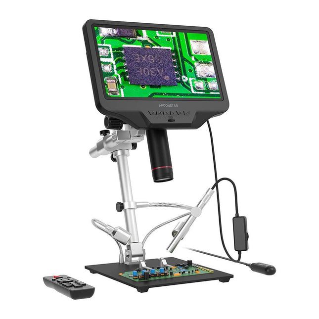
The Andonstar AD409 Pro-ES is a digital microscope with an extra-high stand that is also equipped with an endoscope. The microscope allows clear observation of the sides of components, the inside of pipes, etc., enabling 360° observation without dead angles. The microscope also has a remote control that allows you to easily switch between the following image modes: two-lens, microscope and endoscope.
Features
High-quality metal lens and focusing barrel
Professional HDMI digital microscope supports multiple output methods
Soldering Microscope with Pro Metal Stand
Unique UV filter design
8 Levels adjustable LED Lights
Convenient Wireless Remote Control
Professional Measurement Software
Specifications
Screen size
10.1 inch (25.7 cm)
Image sensor
4 MP
Video output
UHD 2880x2160 (24fps)FHD 1920x1080 (60fps/30fps)HD 1280x720 (120fps)
Video format
MP4
Magnification
Up to 300 times (27 inch HDMI monitor)
Photo resolution
Max. 12 MP (4032x3024)
Photo format
JPG
Focus range
Min. 5 cm
Frame Rate
Max. 120fps
Video interface
HDMI
Storage
microSD card (up to 64 GB)
PC support
Windows, PC software with measurement
Mobile phone, tablet terminal support
Support WiFi connection and measurement
Power source
5 V DC
Light source
2 LEDs with the stand
Endoscope
Yes
Stand size
18 x 20 x 32 cm
Included
1x Andonstar AD409 Pro-ES Digital Microscope
1x Endoscope
1x Metal stand with 2 LEDs
1x UV filter (already assembled in the lens)
1x IR remote
1x Switch cable
1x Power adapter
1x Wrench
2x Metal clips
1x HDMI cable
1x User manual
Downloads
Manual
Software