Comprehensive Book-Hardware Bundle for the RP2040 Microcontroller with over 80 Projects
Unlock the potential of modern controller technology with the Raspberry Pi Pico in this bundle. Perfect for both beginners and experienced users, the easy-to-follow guide takes you from the basics of electronics to the complexities of digital signal processing. With the Raspberry Pi Pico, the dedicated hardware kit and MicroPython programming, you will learn the key principles of circuit design, data collection, and processing.
Get hands-on with over 80 projects like a stopwatch with an OLED display, a laser distance meter, and a servo-controlled fan. These projects are designed to help you apply what you've learned in real-world scenarios. The book also covers advanced topics like wireless RFID technology, object detection, and sensor integration for robotics.
Whether you're looking to build your skills in electronics or dive deeper into embedded systems, this bundle is the perfect resource to help you explore the full potential of the Raspberry Pi Pico.
Contents of the Bundle
1x Project Book (273 pages)
1x Smart Car Kit
Electronic Parts
2x Solderless breadboard (400 holes)
1x Solderless breadboard (170 holes)
5x Colorful 5 mm LEDs (green, red, blue, yellow and white)
1x Laser transmitter
1x Passive buzzer
1x Micro USB cable (30 cm)
1x 65 Jumper wires
1x 20 cm male to female Dupont wire
1x Clear case
1x Magnet (diameter: 8 mm, thickness: 5 mm)
1x Rotary potentiometer
10x 2 KΩ resistors
2x M2.5x30 mm copper pillars
10x Phillips pan head screws
10x M2.5 nickel hex nuts
1x 2-inch dual-purpose screwdriver
Modules
1x RGB module
1x 9G servo
1x Dual-axis XY joystick module
1x RC522 RFID module
1x 4 Bits digital LED display module
1x Traffic light display module
1x Rotary Encoder module
1x 1602 LCD Display module (Blue)
1x Photoresistor module
1x DC motor with male Dupont wire
1x Fan blade
1x Raindrops module
1x OLED module
1x Membrane switch keyboard
1x Mini magnetic spring module
1x Infrared remote control
1x Infrared receiver module
1x DC stepper motor driver board
1x Button
Sensors
1x Vibration sensor
1x Soil moisture sensor
1x Sound sensor
1x Mini PIR motion sensor
1x Temperature & Humidity sensor
1x Flame sensor
2x Crash sensor
2x Tracking sensor
1x Ultrasonic sensor
Learn to Build Intelligent Embedded Systems
Build smarter embedded systems with Arduino UNO Q. This book gives you the tools, knowledge, and confidence to turn ideas into intelligent, working solutions using the Arduino UNO Q platform. Discover how to build intelligent embedded systems with the Arduino UNO Q and AI.
Unlock the full potential of the Arduino UNO Q, a next-generation platform that combines the real-time power of the STM32U585 microcontroller with the flexibility of a Qualcomm Dragonwing QRB2210 microprocessor.
Learn how to rapidly prototype real-world applications using the Arduino IDE for low-level embedded control and Python in Arduino App Lab for high-level development.
Build confidence through hands-on projects that guide you step by step from basic board features to complete working systems.
Explore ready-to-use, AI based Arduino App Lab examples and see how they can jump-start your development and reduce time to deployment.
Step into the world of Edge AI with a clear, practical introduction to Edge Impulse Studio—no prior AI experience required.
Follow a complete, real-world workflow to create a Keyword Spotting AI application, covering data collection, model training, optimization, and on-device inference using the Edge Impulse Studio.
Bridge the gap between embedded systems and machine learning and learn how to bring intelligence directly onto your hardware.
Perfect for embedded engineers, educators, students, and makers looking to stay ahead in AI-enabled product development.
Diese Ausgabe steht allen GOLD- und GREEN-Mitgliedern auf der ElektorMagazine-Website zum Download bereit!
Sie sind noch kein Mitglied? Hier klicken!
Stromquelle zum Testen von (Z-)DiodenPrüfen von Z-Dioden von 1 bis 54 V bei 1 bis 50 mA
ESD-Armband-TesterEin Tool zur Funktionsprüfung von Erdungsarmbändern
Transientenmesser für LabornetzteileEin reproduzierbarer Lastsprung-Generator für Labornetzteile
3D-Viewer für HTML-SeitenEinfach und fast ohne Code
LED-Blinkleuchte für Tore und mehr mit akustischem Alarm
Benötigen Sie Leiterplatten? Der Elektor-Leiterplattenservice ist für Sie da.
Zahnbürsten-TimerMit einem kleinen PIC
Ein berührungsloses magnetisches Kombinationsschlossmit dem AS5600-Drehpositionssensor
Rauscharmer, batteriebetriebener Vorverstärkerfür dynamische Mikrofone
Das Arduino Nano TestLabMessen, Steuern, Regeln
Rhythmische BassleuchteBetonen Sie den Rhythmus Ihrer Musik
Low-cut-FilterKein Risiko von Audio-Rückkopplungen in Ihrem System
Präziser 1-Hz-Rechteckwellengenerator für SteckbrettEine zuverlässige CMOS-basierte Taktquelle
555 auf den Kopf gestelltTastverhältnisse bis hinunter auf Null
Vom „Halfgeleidergids“ zu Circuit Specials65 Jahre Elektronik-Innovation
Galvanische TrennungCAN-Schnittstelle mit Digitalisolator und Powermodul
SpongillatorEin schwammbasierter Oszillator
Echter Zufallszahlengeneratormit integriertem Chi-Quadrat-Test
Euklidischer Sequencer ohne MikrocontrollerTrigger-Pattern und CV-Sequenzen mit einfacher CMOS-Logik
Programmieren mit TLScriptEine Skriptsprache zum Messen, Testen und Steuern
Schaltungsdesign: Tipps von Experten
RückkopplungWas ist das und warum ist sie wichtig?
Ein Board, endlose Ideen: Arduino UNO QVon Retro-Gaming zur Echtzeit-Umweltüberwachung
So bringen Sie eine Donut-Antenne in Ordnung
Standby-KillerEin echter Ein-/Ausschalter für den Fernseher
Akkus im TestAkkus vermessen mit dem Arduino Nano
Stromversorgung für Audio-EndstufenEin gutes Netzteil ohne Netzbrummen
Lochrasterplatinen für HFSchnelle Aufbauten mit DIY-Prototyping-Boards
T3-ÜberspannungsschutzEin Typ-3-Schutzmodul für empfindliche Geräte
IoT-Raumthermostat-Platinemit dem Xiao-MCU-Modul auf Basis des ESP32-C3/S3
Von starr zu smartFlexible und gedruckte Elektronik – zwischen Vision und industrieller Realität
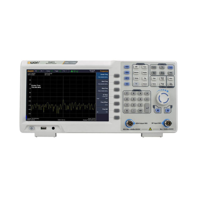
The OWON XSA815-TG (9 kHz-1.5 GHz) is a cost effective spectrum analyzer with tracking generator included and a frequency resolutions of 1 Hz.
Features
Frequency Range from 9 kHz to 1.500009 GHz
9-inch display
9 kHz to 1 MHz -95 dBm Displayed Average Noise Level, 1 MHz to 500 MHz 140 dBm (Typical), <-130 dBm
Phase Noise
-10 kHz <-80 dBc/Hz
100 kHz <-100 dBc/Hz
1 MHz <-115 dBc/Hz
Resolution Bandwidth (-3 dB): 1 Hz to 1 MHz, in 1-3-5-10 sequence
Tracking Generator Kit: 100 kHz to 1.500009 GHz
Specifications
Frequency Range
9 kHz to 500.009 MHz
Frequency Resolution
1 Hz
Frequency Span
9 kHz to 1.500009 GHz
Span Range
0 Hz, 100 Hz to max frequency of instrument
Span Uncertainty
±span / (sweep points-1)
SSB Phase Noise (20°C to 30°C, fc=1 GHz)
Carrier Offset
10 kHz <-80 dBc/Hz | 100 kHz <-100 dBc/Hz | 1 MHz <-115 dBc/Hz
Resolution Bandwidth (-3 dB)
1 Hz to 1 MHz, in 1-3-5-10 sequence
RBW Accuracy
<5% typical
Resolution Filter Shape Factor (60 dB: 3 dB)
<5 typical
Video Bandwidth (-3 dB)
10 Hz to 1 MHz, in 1-3-5-10 sequence
Amplitude measurement range
DANL to +10 dBm, 100 kHz to 10 MHz, Preamp Off
DANL to +20 dBm, 10 MHz to 1.5 GHz, Preamp Off
Reference Level
-80 dBm to +30 dBm, 0.01dB by step
Preamp
20 dB, nominal, 100 kHz to 1.5 GHz
Input Attenuator
0 to 40 dB, 1 dB by step
Display Average Noise Level Input attenuation = 0 dB, RBW = VBW = 100 Hz, sample detector, trace average ≥ 50, 20°C to 30°C, input impedance = 50 Ω)
Preamp Off 9 kHz to 1 MHz
-95 dBm (Typical), <-88 dBm
Preamp Off 1 MHz to 500 MHz
-140 dBm (Typical), <-130 dBm
Preamp On 100 kHz to 1 MHz
-135 dBm (Typical), <-128 dBm
Preamp On 1 MHz to 500 MHz
-160 dBm (Typical),<-150 dBm
Tracking Generator (optional)
Frequency Range
100 kHz to 1.500009 GHz
Output power level range
-40 dBm to 0 dBm
Output level resolution 1 dB
Output flatness
Relative to 50 MHz | ±3 dB
Tracking generator spurious
Harmonic spurious -30 dBc (Tracking generator output power -10 dBm)
Non-harmonic spurious -40 dBc (Tracking generator output power -10 dBm)
Tracking generator to input terminal isolation
-60 dB (Tracking generator output power 0 dBm)
Tracking generator to input terminal isolation
-60 dB (Tracking generator output power 0 dBm)
Tracking generator to input terminal isolation
-60 dB (Tracking generator output power 0 dBm)
Dimensions
375 x 185 x 120 mm
Weight
3.7 kg
Included
1x XSA815-TG
1x 220 V AC power cord
1x USB Cable
1x Quickstart guide
Downloads
Quick Guide
Specifications
The OWON ADS900A series is a compact 12-bit digital oscilloscope offering up to 2 GSa/s, 100 Mpts memory, and 125/250 MHz bandwidth. With its 7" multi-touch display, FFT, protocol decoding, and integrated logic analyzer, it delivers precise signal analysis for lab, workshop, and field applications.
Specifications
ADS914A
ADS924A
Bandwidth (-3 dB)
125 MHz
250 MHz
Channels
4
Max. sample rate
2 GSa/s (single-channel) 1 GSa/s (dual-channel) 500 MSa/s (full-channel)
DC Gain Accuracy
3% (≤1 mV)
2% (≥2 mV)
Max memory depth
100M
Vertical resolution
12 bits
Relay time accuracy
±25 ppm (typical)
Input Impedance
1 MΩ±2%, parallel with20 pF±5 pF
Probe Attenuation Coefficient
1.00μX-1M.00X,step by 1-2-5, support custom
Trigger type
Edge, Video, Pulse, Slope, Runt, Windows, Timeout, Nth, Logic, RS232/UART, I²C, SPI CAN, LIN
Bus decoding
RS232/UART, I²C, SPI, CAN, LIN
Auto measurement
Period, Frequency, +Width, -Width, Rise Time, Fall Time, Scr Duty, +Duty,-Duty, Vavg, Vpp, VRMS, Overshoot, Vmax, Vmin, Vtop, CycRms, Vbase, Vamp, Preshoot, Std Dev, +Pulse Cnt, -Pulse Cnt, Rise Cnt, Fall Cnt, Area, Cyc Area, Delay(A↑-B↑), Delay(A↑-B↓), Delay(A↓-B↑), Delay(A↓-B↓), Phase(A↑-B↑)
Phase(A↑-B↓), Phase(A↓-B↑), Phase(A↓-B↓), FRR(A↑-B↑), FRF(A↑-B↓)
FFR(A↓-B↑), FFF(A↓-B↓), LRR(A↑-B↑), LRF(A↑-B↓), LFR(A↓-B↑), LFF(A↓-B↓)
Waveform Math
+, -, *, /, &&, ||, ^, !, Intg, Diff, Sqrt, Function operation (Lg / Ln / Exp / Abs / Sine / Cosine / Tan), FFT, FFT rms, User Defined, digital filter (low pass, high pass, band pass, band reject)
Frequency counter
6-digit frequency counter
Maximum frequency: maximum analog bandwidth of oscilloscope
Voltmeter
Support DC, AC+DCrms, ACrms, Resolution: 4 digits (ACV/DCV)
Logical Analyzer Specifications
Number of channels
16 input channels (D0-D15) (D0 to D7, D8 to D15)
Max. input voltage
±40V peak CAT I, transient overvoltage 800Vpk
Input Impedance
100kΩ, 8 pF
Vertical resolution
1 bit
Other
Communication Interface
HDMI, USB device, USB Host, Trig Out (P/F), LAN
Display
7 inch (1024x600), capacitive multi-touch screen
Power supply interface
USB-C
Dimensions
260 x 160 x 78 mm
Weight
1.5 kg
Included
1x OWON ADS914A Oscilloscope
1x Power Adapter
1x Power Cord
1x USB Cable
1x Probe
1x Quick Guide
Downloads
Manual
Quick Guide
PC Software
High-Performance LoRa Communication Device
The Elecrow ThinkNode M5 is a compact, portable LoRa communication device designed for off-grid messaging, location sharing, and outdoor use. Powered by an ESP32-S3 processor and an SX1262 LoRa chip, it comes pre-installed with Meshtastic firmware and can be configured conveniently via Bluetooth using the official Meshtastic app.
The integrated multi-GNSS module supports GPS, GLONASS, BeiDou, and QZSS for reliable positioning and location sharing. Messages and device information are displayed on the energy-efficient 1.54-inch e-paper screen, while the built-in 1,200 mAh rechargeable battery enables extended mobile operation.
With its integrated LoRa antenna, compact housing, RTC, and support for both Meshtastic and MeshCore firmware, the ThinkNode M5 is a practical communication solution for hiking, camping, remote locations, and emergency situations where conventional mobile networks are unavailable.
Features
LoRa communication
Multi-GNSS positioning
1,200 mAh rechargeable battery
1.54-inch e-paper display
Built-in RTC
Compatible with MeshCore
Compatible with Meshtastic
Specifications
Main Processor (ESP32-S3)
CPU/SoC
Xtensa 32-bit LX7 dual-core processor, clocked at up to 240 MHz
System Memory
512 KB SRAM, 8 MB PSRAM
Storage
4 MB Flash, 384 KB ROM
Firmware
Meshtastic firmware is fully compatible, and the signal is transmitted in LoRa mode
EPD (Electronic Paper Display)
Display Size
1.54 inch EPD (monochrome Ink screen)
Display Materials
E-lnk (Electronic Ink)
Resolution
200 x 200
Driver Chip
SSD1681 (via SPI or I²C interface)
Global Fresh Time
2s
Wireless Communication
Bluetooth
Bluetooth Low Energy and Bluetooth 5.0 (phone configuration)
LoRa
SX1262 LoRa Module, EU 868 MHz(external antenna)
Hardware
Interfaces
USB-C, RP-SMA
Function
GPS Location (GPS, GLONASS, BeiDou, QZSS), EPD Display, RTC, USB 2.0, PMU power management (built-in 1200 mAh lithium battery), buzzer, etc.
Button
Knob Switch, Function Button, Page Turn Button, GPS Switch, Reset Button
LED Indicator
Power supply, GPS/LoRa indication
Others
Power Input
5 V/1 A, supports USB or lithium battery power supply
Power consumption
The maximum working current is about 340 mA (CPU + LoRa module), and the low power consumption is about 34 uA
Operating Temperature
-10~50°C
Storage Temperature
-20~60°C
Relative humidity
10-95%, @ 40°C (non-condensing)
Enclosure
ABS Plastic
Dimensions
82 x 51.6 x 26.3 mm
Weight
81 g
Included
1x Elecrow ThinkNode M5
1x LoRa antenna
1x USB-C cable
1x Manual
Downloads
Manual
Learn how to use the ESP32 Microcontroller and MicroPython programming in your future projects!
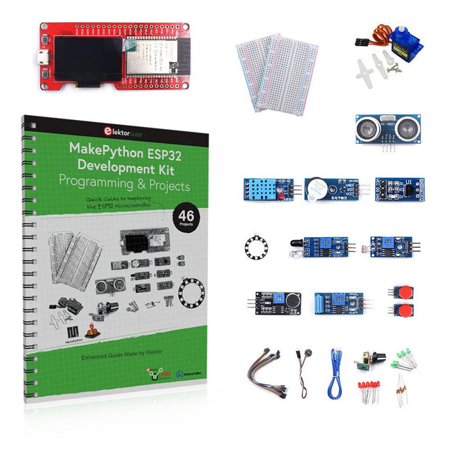
The project book, written by well-known Elektor author Dogan Ibrahim, holds many software- and hardware-based projects especially developed for the MakePython ESP32 Development Kit. The kit comes with several LEDs, sensors, and actuators. The kit will help you acquire the basic knowledge to create IoT projects.
The book’s fully evaluated projects feature all the supplied components. Each project includes a block diagram, a circuit diagram, a full program listing, and a complete program description.
Included in the kit
1x MakePython ESP32 development board with LCD
1x Ultrasonic ranging module
1x Temperature and humidity sensor
1x Buzzer module
1x DS18B20 module
1x Infrared module
1x Potentiometer
1x WS2812 module
1x Sound sensor
1x Vibration sensor
1x Photosensitive resistance module
1x Pulse sensor
1x Servo motor
1x USB cable
2x Button
2x Breadboard
45x Jumper wire
10x Resistor 330R
10x LED (Red)
10x LED (Green)
1x Project book (206 pages)
46 Projects in the Book
LED Projects
Blinking LED
Flashing SOS
Blinking LED – using a timer
Alternately flashing LEDs
Button control
Changing the LED flashing rate using pushbutton interrupts
Chasing-LEDs
Binary-counting LEDs
Christmas lights (random-flashing 8 LEDs)
Electronic dice
Lucky day of the week
Pulsewidth Modulation (PWM) Projects
Generate a 1000-Hz PWM waveform with 50% duty cycle
LED brightness control
Measuring the frequency and duty cycle of a PWM waveform
Melody maker
Simple electronic organ
Servo motor control
Servo motor DS18B20 thermometer
Analog To Digital Converter (ADC) Projects
Voltmeter
Plotting the analog input voltage
ESP32 internal temperature sensor
Ohmmeter
Photosensitive resistance module
Digital To Analog Converter (DAC) Projects
Generating fixed voltages
Generating a sawtooth-wave signal
Generating a triangular-wave signal
Arbitrary periodic waveform
Generating a sinewave signal
Generating accurate sinewave signal using timer interrupts
Using The OLED Display
Seconds counter
Event counter
DS18B20 OLED based digital thermometer
ON-OFF temperature controller
Measuring the temperature and humidity
Ultrasonic distance measurement
Height of a person (stadiometer)
Heart rate (pulse) measurement
Other Sensors Supplied with the Kit
Theft alarm
Sound-activated light
Infrared obstacle avoidance with buzzer
WS2812 RGB LED ring
Timestamping temperature and humidity readings
Network Programming
Wi-Fi scanner
Remote control from the Internet browser (using a smartphone or PC) – Web Server
Storing temperature and humidity data in the Cloud
Low-Power Operation
Using a timer to wake up the processor
With the JOY-iT PS1440-C-Pro, you get a programmable laboratory power supply that delivers DC voltages ranging from 0.01 to 60 V and DC currents from 0.01 to 24 A at the voltage output.
The intuitive control panel allows you to program, store, and recall up to 9 different DC voltage settings. You can also configure individual protection and limiting functions—such as overvoltage protection. All settings are easily adjusted via the keypad and/or rotary control and are clearly shown on the high-resolution 2.4" color display.
For enhanced connectivity, the PS1440-C-Pro includes an RS485 interface for robust, long-distance communication. This makes it ideal for complex setups where signal stability, noise immunity, and reliable data transfer are critical. The included connector ensures a secure connection, improving the overall reliability and performance of your laboratory equipment setup.
Features
Complete device ready for immediate use
RS485 interface
Battery charging function
Values can be entered conveniently via keypad
Over current & over voltage protection adjustable
Integrated RTC, NTC temperature sensor
Included detailed documentation in English, German & French
Specifications
Input voltage
230 V
Output voltage
060 V
Output current
0-24 A
Output power
0-1440 W
Input voltage accuracy
±1% +5 digits
Output voltage accuracy
±0.3% +3 digits
Output current accuracy
±0.5% +5 digits
Battery voltage
±0.5% +3 digits
Input voltage measurement resolution
0.01 V
Output voltage measurement resolution
0.01 V
Current measurement resolution
0.01 V
Battery voltage measurement resolution
0.01 V
Response time in constant voltage mode
2 ms @ 0.1-5 A
Load regulation in constant voltage mode
±0.1% +2 digits
Load regulation in constant current mode
±0.1% +3 digits
Measuring range electric charge
0-9999.99 Ah
Measuring range energy
0-9999.99 Wh
Statistical errors in electric charge & energy
±2%
Output ripple
100 mV VPP @ 12 V150 mV VPP @ 24 V
Sensor temperature detection range
−10~100°C (0-200°F)
Sensor temperature detection accuracy
±3°C (±6°F)
Working mode
Step-down operation
Screen brightness setting
Level 0-5, 6 levels in total
Permissible working temperature
−10~40°C (0-104°F)
Dimensions
170 x 93 x 340 mm
Included
JOY-iT PS1440-C Power Supply
2-pin connector for RS485 interface
Power cord
Manual
Downloads
Datasheet
MODBUS Protocol
PC Software
Driver for Windows
The Joy-Pi Advanced is a compact and powerful device that allows you to realize your projects quickly and easily. Whether you already have a lot of experience, or next to none, the Joy-Pi Advanced lets you unleash your creativity. Thanks to its compatibility with a wide range of platforms, including Raspberry Pi, Raspberry Pi Pico, Arduino Nano, BBC micro:bit, and NodeMCU ESP32, you can easily and quickly access your preferred platform.
In addition, the Joy-Pi Advanced features more than 30 stations, lessons, and modules, giving you an unlimited variety of ways to get your projects done. With the self-developed learning center, you can not only improve your skills but also create new projects. The learning center offers a wealth of information and tutorials that will guide you step by step through your projects.
Joy-Pi Advanced is characterized in particular by its intelligent switch units, which allow an extended use of the available pins. A total of three switch units are integrated, each equipped with 12 individual switches that provide precise control of the connected sensors and modules. This system solves the well-known problem of limited pin count that occurs with conventional microcontrollers. The switch units allow you to operate a large number of sensors and modules in parallel by switching them on and off individually. This simulates multiple pin assignment, allowing you to exploit the full power of your projects without compromising functionality.
By combining innovative adapter boards and the micro:bit slot, you can achieve seamless compatibility with a wide range of microcontrollers such as Raspberry Pi Pico, NodeMCU ESP32, micro:mit and Arduino Nano. The specially developed adapter boards are designed to perfectly match the respective microcontroller. By plugging the microcontroller onto the appropriate adapter board and then plugging it into the micro:bit slot, the Joy-Pi Advanced quickly and easily becomes compatible with the different microcontrollers. This allows seamless integration of your preferred platform and the ability to combine the strengths of the different microcontrollers in your projects. This way, you can fully focus on your creative projects without worrying about the compatibility of different microcontrollers. The Joy-Pi Advanced simplifies the development process and gives you the possibility to design your projects flexibly and individually.
Features
Highly integrated development platform & learning center
Fast, easy & wireless combination of various sensors & actuators
Installation option for Raspberry Pi 4
Compatible with various microcontrollers
Self-developed, didactic learning platform for Raspberry Pi & Windows
Specifications
Compatible to
Raspberry Pi 4, Arduino Nano, NodeMCU ESP32, BBC micro:bit, Raspberry Pi Pico
Installed sensors, actuators & components
39
Learning platform
Over 40 entries in the know-ledge database, 10 projects, 10 learning tasks, 14 visions
Displays
7-segment display, 16x2 display, 1.8“ TFT display, 0.96" OLED display, 8x8 RGB matrix
Sensors
DS18B20, shock sensor, hall sensor, barometer, sound sensor, gyroscope, PIR sensor, Light barrier, NTC, Light sensor, 6x touch sensor, color sensor, ultrasonic distance sensor, DHT11 temperature & humidity sensor
Control
Joystick, 5x switches, potentiometer, rotary encoder, 4x4 button matrix, relays, PWM fan
Motors
Servo interface, Stepper motor interface, Vibration motor
Measuring & conversion modules
Analog-Digital Converter, Level converter, voltmeter, Variable voltage supply
Other components
RTC real time clock, buzzer, EEPROM memory, infrared receiver, breadboard, RFID reader
Adapter boards
Adapter for NodeMCU ESP32, Arduino Nano & Raspberry Pi Pico, Board connectors for Raspberry Pi & External Boards
Electronic components
Infrared remote control, RFID chip, RFID card, 6x alligator clips, microSD card reader, servo motor, stepper motor, 32 GB microSD card
Components
40x resistors, 3x green LEDs, 3x yellow LEDs, 3x red LEDs, 1x transistor, 5x buttons, 1x potentiometer, 2x capacitors
Other accessories
Screw assortment, screwdriver, accessory storage bag, power supply & power cable, servo mount
Power supply
Built-in power supply: 36 W, 12 V, 3 A Case connector: Small device plug C8
Voltage outputs
12 V, 5 V, 3.3 V, Variable voltage output (2-11 V)
Data buses & signal outputs
I²C, SPI, Analog to digital converter
Battery (RTC)
CR2032
Dimensions
327 x 200 x 52 mm
Included
Raspberry Pi 4 (8 GB RAM)
Downloads
Joy-Pi website
Datasheet
Manual
Complete ESP32 microcontroller learning course featuring a custom-designed MCU expansion board, hands-on projects, and a comprehensive online guide – perfect for learning hardware, programming, and connectivity step by step.
A Practical Introduction to Embedded Systems with the ESP32
This course is designed for readers who are new to embedded systems and looking for a structured, example-driven way to get started. If you’ve explored general-purpose electronics or Arduino-based materials but found them too broad or lacking in practical guidance, this course offers a more focused alternative.
Using the "ESP32 by Example Kit" (EEK) – a compact and affordable set of components featuring LEDs, sensors, an OLED display, and a motion processor – you’ll work with a consistent hardware setup throughout the course. Once assembled, the EEK stays mostly unchanged, allowing you to concentrate on learning and experimentation without constant reconfiguration.
Topics include:
Understanding and programming the ESP32 microcontroller
Writing and deploying code with the Arduino IDE
Exploring cyber-physical systems, culminating in basic drone control
No prior experience with Arduino or embedded development is required. Each section features hands-on examples and mini-projects designed to reinforce key concepts and inspire deeper exploration. By the end of the course, you’ll be able not only to reproduce the book’s examples but also to build on them with your own ideas and applications.
Whether you're interested in embedded programming, interactive systems, or introductory drone control, this course provides a clear and practical path to getting started.
What you'll learn?
Embedded programming with the ESP32 using the Arduino IDE
Real-time sensor input and control via buttons, LEDs, and displays
Gesture-based interaction using the MPU6050 motion sensor
Bluetooth gamepad integration and drone control simulation
Wi-Fi and UDP networking, local web servers, and NTP
MQTT communication with cloud platforms like AWS and Arduino IoT
How to build and deploy full-featured IoT systems
Perfect for
Students and self-learners exploring embedded systems
Makers and IoT enthusiasts looking to improve their hardware skills
Educators and trainers seeking ready-to-teach material
Developers moving beyond Raspberry Pi or Arduino basics
Support when you need it
Access to instructors via Elektor Academy
Helpful community forums and essential documentation
What's inside the Box (Course)?
New 384-page book: "ESP32 by Example" (valued at €45)
Elektor ESP32 by Example Kit (EEK): Microcontroller Extension Board with 6 LEDs and 6 Buttons installed + OLED Display, MPU6050 3-axis Accelerometer and Gyroscope Module (valued at €40)
Adafruit HUZZAH32 – ESP32 Feather MCU Board (valued at €30)
ESP32 Cheap Yellow Display Board (valued at €25)
DHT11 Humidity & Temperature Sensor
Breadboard
Jumper wires
USB-C cable
Access to the full course on the Elektor Academy Pro Learning Platform
Instructional videos
Downloadable Arduino project files for every module
Learning Material (of this Box/Course)
▶ Click here to open
Module 1 – Getting Started with the ESP32 & EEK
Module 2 – Digital Output – LEDs and GPIO
Module 3 – Switches and Input Handling
Module 4 – EEK and PWM
Module 5 – OLED and Display Output
Module 6 – Motion Sensing with the MPU6050
Module 7 – Capstone Project (EEK in Action)
Module 8 – WiFi and Web Control with ESP32
Module 9 – Cloud Concepts using EEK
Module 10 – Hands-on: Arduino IoT Cloud and EEK
Module 11 – BlueTooth and EEK GamePad Integration
Module 12 – Why Drones?
Module 13 – Drone Simulator Concepts
Module 14 – Simple Drone Flight Control
Module 15 – Real-Time Drone Flight Control
Module 16 – Drone Control Mini-Projects
Module 17 – Middleware and Python Scripting
Module 18 – Python Applications for Drone Control
Module 19 – Capstone EEK Control Project and Presentation
About the Author
Dr. Jim Solderitsch is an educator, software architect, systems developer, and cybersecurity researcher with a focus on cyber-physical systems. He currently serves as an Adjunct Professor in Computing Sciences at Villanova University in Pennsylvania.
What is Elektor Academy Pro?
Elektor Academy Pro delivers specialized learning solutions designed for professionals, engineering teams, and technical experts in the electronics and embedded systems industry. It enables individuals and organizations to expand their practical knowledge, enhance their skills, and stay ahead of the curve through high-quality resources and hands-on training tools.
From real-world projects and expert-led courses to in-depth technical insights, Elektor empowers engineers to tackle today’s electronics and embedded systems challenges. Our educational offerings include Academy Books, Pro Boxes, Webinars, Conferences, and industry-focused B2B magazines – all created with professional development in mind.
Whether you're an engineer, R&D specialist, or technical decision-maker, Elektor Academy Pro bridges the gap between theory and practice, helping you master emerging technologies and drive innovation within your organization.