
Search results for "red OR pitaya OR calibrated OR diagnostic OR kit"
-

Elektor Digital Heimautomation und Elektronik für Anfänger (PDF)
Projekte mit Arduino, ESPHome, Home Assistant und Raspberry Pi & Co Dieses E-Book enthält verschiedene Projektbeispiele und beginnt mit einer Einführung in die Elektronik. Es erklärt unter anderem, wie man Home Assistant auf einem Raspberry Pi installiert, wie man Raumklimasensoren für Temperatur und Luftfeuchtigkeit nutzt, das MQTT-Protokoll sowie weitere Schnittstellen einsetzt und ESPHome verwendet, um Sensoren und Aktoren in Home Assistant zu integrieren. Zahlreiche Video-Tutorials ergänzen das Buch. Grundlagen der Elektrotechnik Das Buch beginnt mit einer Einführung in die Elektrotechnik. Ihr lernt die Grundlagen von Spannung, Strom, Widerständen, Dioden und Transistoren. Arduino und Mikrocontroller Ein kompletter Abschnitt widmet sich dem Arduino Uno. Ihr lernt den Aufbau kennen, schreibt erste Programme und erarbeitet praktische Beispiele. Home Assistant und Automatisierung Ihr erfahrt, wie Home Assistant auf einem Raspberry Pi eingerichtet wird, und lernt den Umgang mit Automatisierungen, Szenen und Geräten. Zusätzlich wird auf Zigbee, MQTT und ESP-NOW eingegangen – wichtige Technologien für die Heimautomation. ESP8266, ESP32 und ESP32-CAM Die beliebten ESP-Mikrocontroller werden ausführlich behandelt. Nach einer theoretischen Einführung folgen praktische Projekte, die euch zeigen, wie ihr das Beste aus diesen Geräten herausholen könnt. Sensoren und Aktoren Das Buch erklärt die Funktionsweise und Anwendung zahlreicher Sensoren wie Temperatur- und Luftfeuchtigkeitssensoren, Bewegungsmelder und RFID-Reader. Bei den Aktoren werden Schrittmotoren, e-ink Displays, Servo-Motoren und vieles mehr beleuchtet. Zu allen Geräten gibt es praxisnahe Anwendungsbeispiele. ESPHome Dieses Kapitel zeigt euch, wie ihr Sensoren und Aktoren ohne Programmieraufwand in Home Assistant integriert. Ihr werdet Schritt für Schritt durch die Einrichtung mit ESPHome geführt. LEDs und Lichttechnik In diesem Kapitel lernt ihr verschiedene LED-Typen und deren Einsatzmöglichkeiten kennen. Grundlagen der Lichttechnik werden ebenfalls erklärt. Node-RED Ein eigenes Kapitel ist Node-RED gewidmet. Ihr erlernt die Grundlagen dieses leistungsstarken Tools und werdet Schritt für Schritt durch die Einrichtung und Nutzung geführt. Integrierte Schaltkreise (ICs) In der Elektronik gibt es zahlreiche ICs, die uns das Leben erleichtern. Ihr lernt die wichtigsten kennen und wendet das Wissen in praktischen Projekten an. Programmieren für Profis Fortgeschrittene Themen wie die korrekte Verwendung von Tastern, der Einsatz von Interrupts und die Nutzung eines NTP-Servers für Zeit-Synchronisation werden in diesem Kapitel detailliert behandelt. Downloads GitHub
€ 59,95
Best Price
-
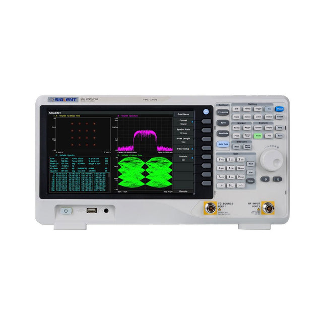
Siglent Siglent SSA3021X Plus Spectrum Analyzer (9 kHz – 2.1 GHz)
The Siglent SSA3021X Plus spectrum analyzer is a powerful and flexible tool for RF signal and network analysis. With a frequency range of 2.1 GHz, the analyzer delivers reliable automatic measurements and multiple modes of operation: spectrum analyzer the base, optional functions include RF power measurement, vector signal modulation analysis, reflection measurement, and EMI test. Applications include broadcast monitoring/evaluation, site surveying, S-parameter measurement, analog/digital modulation analysis, EMI pre-compliance test, research and development, education, production, and maintenance. Features Spectrum Analyzer Frequency Range from 9 kHz to 2.1 GHz –161 dBm/Hz Displayed Average Noise Level (Typ.) –98 dBc/Hz. @ 10 kHz Offset Phase Noise (1 GHz, Typ.) Level Measurement Uncertainty <0.7 dB (Typ.) 1 Hz Minimum Resolution Bandwidth (RBW) Preamplifier (Std.) Tracking Generator (incl. free of charge) Analog and Digital Signal Modulation Analysis Mode (opt.) Reflection Measurement Kit (opt.) EMI Filter and Quasi-Peak Detector Kit (opt.) Advanced Measurement Kit (opt.) 10.1-inch Multi-Touch Screen , Mouse and Keyboard supported Web Browser Remote Control on PC and Mobile Terminals and File Operation Specifications SSA3015X Plus SSA3021X Plus SSA3032X Plus SSA3075X Plus Frequency Range 9 kHz ~ 1.5 GHz 9 kHz ~ 2.1 GHz 9 kHz ~ 3.2 GHz 9 kHz ~ 7.5 GHz Resolution Bandwidth 1 Hz ~ 1 MHz 1 Hz ~ 1 MHz 1 Hz ~ 1 MHz 1 Hz ~ 3 MHz Phase Noise <–99 dBc/Hz <–98 dBc/Hz <–98 dBc/Hz <–98 dBc/Hz Total Amplitude Accuracy <1.2 dB <0.7 dB <0.7 dB <0.7 dB Display Average Noise Level –156 dBm/Hz –161 dBm/Hz –161 dBm/Hz –165 dBm/Hz Included Siglent SSA3021X Plus spectrum analyzer USB cable Power cord Quick start guide Downloads Datasheet Manual Documentation Firmware
€ 1.777,49
-

Elektor Labs Elektor Low-Noise Lab Power Supply
The Elektor Low-Noise Lab Power Supply is a fully analogue, adjustable, medium-power symmetrical bench supply that contains no switching or digital components. It provides an output voltage adjustable between 0 V and ±22 V, and an output current adjustable from 0 A to 1 A. Because it avoids any form of switching circuitry, the design delivers extremely low noise. To display both output voltages and currents, four miniature moving-coil panel meters are used. Most modern laboratory power supplies and AC adapters employ switch-mode techniques. Even the best examples inevitably exhibit high-frequency ripple and other switching artefacts on their output, which can interfere with the testing of sensitive analogue circuits and disturb low-level measurements. To overcome this, the concept here is a completely analogue power supply. Although less efficient than its switch-mode counterparts, the reduced efficiency is of little importance for test-bench use and ensures cleaner, more reliable measurement results. Because many analogue circuits require a symmetrical supply, this design delivers positive and negative output voltages of equal magnitude. A small amount of adjustment is available to compensate for any imbalance. Naturally, a variable current-limit function is also included. The kit includes the components required to build the power supply, except for the transformers. Specifications Output Voltage 0…+22 V, 0, −22 V Output Current 0…+1 A, 0…−1 A Noise −85 dBV, (at 0.95 A/20 V, B = 22 kHz) −84 dBV (at 0.95 A/20 V, B > 500 kHz) Ripple 50 µVRMS (at 950 mA/20 V, B = 22 kHz, mainly 100 Hz component) Included 3x PCBs: Regulator (PCB-1), Mains Filter (PCB-2) and Transformer (PCB-3) All the components except the AC transformers 4x moving-coil meters Additional parts for wiring (wires, banana sockets, IEC Power entry module, etc.) Not included The three AC transformers An enclosure Parts List For the Regulator PCB (240386-1) Resistors (250 mW, 1%) R1 = 12 Ω R2, R8, R37, R62 = 1 MΩ R3, R7, R10, R13, R17, R20, R22, R30, R35, R42, R45, R47, R55, R60 = 100 Ω, 600 mW R4, R5 = 4.7 kΩ R6 = 100 kΩ R9, R12, R14, R36, R38, R39, R61, R63, R66, R72, R78, R79 = 10.0 kΩ, 600 mW R11 = 9.76 kΩ, 600 mW R15, R40 = 44.2 kΩ, 600 mW R16, R41, R77 = 1 kΩ R18, R43 = 1.5 kΩ, 1 W, 5% R19, R44 = 470 Ω, 1 W, 5% R21, R46 = 330 Ω, 600 mW R23, R24, R48, R49 = 1.0 Ω, 1 W R25, R50 = 1 kΩ, 1 W, 5% R26, R28, R51, R53 = 1.000 kΩ 0.1%, 15 ppm/C R27, R29, R52, R54 = 10.00 kΩ 0.1%, 15 ppm/C R31, R56 = 1.2 kΩ, 1 W, 5% R32, R57 = 47 kΩ R33, R58 = 270 Ω R34, R59 = 27 kΩ R64, R69 = 12.0 kΩ R65 = 3.0 kΩ, 600 mW R67, R80 = 470 Ω, 600 mW R68, R70 = 6.8 kΩ, 600 mW R71 = 30.0 kΩ,, 600 mW R73, R74, R75, R76 = 10 MΩ P1, P2, P3 = 10 kΩ, 200 mW, 20%, potentiometer, 1 turns, single, lin., panel mount P4, P5 = 500 Ω, 500 mW, 10%, trimmer, 25 turns, 3296Y-1-501LF Bourns P6, P7 = 10 kΩ, 500 mW, 10%, trimmer, 25 turns, 3296Y-1-501LF Bourns Capacitors C1 = 100 nF, 50 V, 10%, ceramic X7R, LS 5 mm C2, C3, C6, C7, C30 = 10 µF, 63V, 20%, LS 2.5 mm, 3000hours@105°C C4, C5, C8, C9, C13, C14, C18, C19, C23, C24, C28, C29, C31, C32, C38, C39 = 100 nF, 250 V, 10%, PET, LS 7.5 mm C10, C20 = 47 nF, 100 V, 5%, PET, LS 5 mm C11, C21 = 10 nF, 100 V, 5%, PET, LS 5 mm C12, C22 = 220 µF, 35 V, 20%, 0.024 Ω, LS2.5/3.5 mm, Ir 3.4 A, 2000hours@125°C, polymer C15, C25 = 120 µF, 50 V, 20%, ESR 0.02 Ω, Diam. 10 mm max., LS 5 mm C16, C26 = 15 nF, 100 V, 5%, PET, LS 5 mm C17, C27 = 47 nF, 100 V, 5%, PET, LS 5 mm C33, C34 = 22 µF, 50 V, 20%, LS 2 mm, 10000 hours @ 105°C C35, C36, C44, C45 = 1 µF, 100 V, 10%, LS 5 mm, ceramic X7R C37 = 100 uF, 50 V, 20%. LS 3.5 mm C40, C41, C42, C43, C46, C47, C48, C49 = 1000 µF, 50 V, 20%, LS 5/7.5 mm, Ir 3.32 A, 10000hours@105°C, D 16 mm C50, C51, C52, C53 = 47 nF, 100 V, 10%, ceramic X7R, LS 5 mm Inductors L1, L2 = 4.7 µH, 3.2 A, 0.033 Ω, LS 5 mm, RLB0914-4R7ML Bourns L3 = Commom mode choke, 14.5 mH, 3 A, SSRH24NH-30145 Kemet Semiconductors D1, D2, D3, D4, D5, D9, D10, D11, D15 = BAT85, DO-34 D6, D7, D12, D13 = SR560, DO-201AD D8, D14, D16 = 1N4148, DO-35 D17 = Zenerdiode, 5.6 V, 0.5 W, DO-41 D18, D19 = 1N4004, DO-41 D20, D21 D22, D23 = V30100CI-M3/P, dual common cathode, TO-220 D24 = Zener diode, 30 V, 1 W, DO-41 LED1, LED2 = LED, red, T-1 (3 mm) LED3, LED4 = LED, green, T-1 (3 mm) TVS1, TVS2 = BZW50-33B, R6 T1, T2, T4 = BC337.25, TO-92 T3 = NJW0302G, TO-3P T5, T6, T8 = BC327.25, TO-92 T7 = NJW0281G, TO-3P T9 = BD139, TO-126 (SOT-32) IC1 = LM334Z, TO-92 IC2 = LM4040AIZ-5.0/NOPB, TO-92 (TO-226AA-3) IC3, IC4 = OPA2992IDR, SOIC-8 IC5, IC6 = OPA4992IDR, SOIC-14 IC7 = OPA992IDBVR, SOT-23-5 IC8 = LM339N, DIP-14 IC9 = LM317, TO-220 IC10 = LM337, TO-220 Others F1, F2 = 5×20 mm fuse, 1.6 A, fast acting HS1, HS2 = Heatsink MC33271 (for T3/T7), 2.7°C/W, PCB mount, height 63.5 mm K1, K4 = 3-way screw terminal block, LS 3.5 mm, max. 1.5 mm² K2, K3 = 3-way screw terminal block, LS 3.5 mm, max. 1 mm² M1, M3 = Moving coil meter, Range 30 V, type 91C4, 45×45 mm M2, M4 = Moving coil meter, Range 1 A, type 91C4, 45×45 mm² RE1 = Relay DPDT,5V, UA2-5NU Miscellaneous 3× 3-way screw terminal block, LS 3.5 mm, max. 1 mm² (for P1, P2, P3) 4× Pin header, 1×2, vertical, pitch 2.54 mm (for LED1, LED2, LED3, LED4) 4× Pin socket, 1×2, vertical. pitch 2.54 mm (for LED1, LED2, LED3, LED4) 2× Heatsink FK222SA220, 20°C/W, PCB mount (for IC9 & IC10) 2× Mica thermal pad for TO-220, 12×18×0.05 mm (for IC9 & IC10) 2× Insulating bushing IB 6, TO-220 (for IC9 & IC10) 2× Ceramic thermal pad, 23×20×2 mm (for T3 & T7) 2× PCB Fuse Holder, for 5×20 mm fuse, 10 A (for F1, F2) 2× Cover for PCB Fuse Holder, transparent (for F1, F2) 2× 2-way screw terminal block, LS 3.5 mm, max. 1 mm² (for M1 & M3) 2× 2-way screw terminal block, LS 3.5 mm, max. 1.5 mm² (for M2 & M4) 8× M3 solder lug, thickness 0.35 mm (for M1…M4) M4 solder lug, thickness 0.35 mm (to connect 4 mm banana connectors) Screened cable, 1 pair, 2×24 AWG/0.22 mm², 1 m (for P1, P2 & P3) IC socket, DIP, 14 contacts (for IC8) M3 washer, plain, steel M3 screw, 16 mm, steel, pan head M3 nut M3 spring washer 50 mm M3 standoff, steel, male-female 12 mm M3 standoff, steel, male-female 10 mm M3 standoff, steel, male-female M3 screw, 8 mm, steel, pan head For the Mains Fiter PCB (240386-2) Resistor R1 = 220 kΩ, 1 W, 500 V, 5% Capacitors C1, C2 = 470 nF, 305 VAC, Class X2, 11 × 27 mm max., LS 15/22.5 mm C3, C4, C5, C6 = 2.2 nF, 300 VAC, Class Y2, 13 × 4 mm, LS 10 mm, PP Inductors L1, L2 = Common-mode choke, 6.8 mH, 1.7 A, TDK B82732R2172B030 Semiconductor MOV1 = TVS varistor, 300 VAC, S14K300 (230 VAC, B72214S0301K101) and SK14K150 (150 VAC, B72214S0151K101) Others K1, K2 = 3-way screw terminal block, LS 7.62 mm F1 = Time-delay fuse, 0.5 A (230 VAC) or 1 A (115 VAC) Miscellaneous 1× Fuse holder, 5×20 mm, 10 A, 500 VAC 1× Transparent fuse cover 4× 10 mm M3 standoff, steel, male–female 4× M3 screw, 8 mm, steel, pan head 4× M3 nut For the Transformer PCB (240386-3) Resistors R1, R2 = 2.7 kΩ, 600 mW, 1% R3 = 10.0 kΩ, 600 mW, 1% Capacitor C1 = 220 µF, 50 V, 20%, Ø10 mm, LS 5 mm, 4000 h @ 105°C Transformers (not included in this kit!) TR1, TR2, TR3 = 2×7 V, 25 VA, PCB-mounted toroid, 70060K Talema Semiconductors D1–D4 = 1N4148, DO-35 D5, D6 = 1N4004, DO-41 D7 = Zener 5.6 V, 1.3 W, DO-41 LED1 = LED, red, T-1 (3 mm) IC1, IC2 = MOC8021M, CTR ≥ 1000%, DIP-6 Others F1, F2, F3 = 160 mA time-delay fuse (230 VAC) or 315 mA time-delay fuse (115 VAC) K1 = 2-way screw terminal block, LS 7.62 mm K2 = 3-way screw terminal block, LS 3.5 mm, max 1.5 mm² K3, K4 = 3-way screw terminal block, LS 3.5 mm, max 1 mm² RE1, RE2 = Relay DPDT, 5 A/250 VAC / 24 VDC Miscellaneaous 1× Pin header 1×2, pitch 2.54 mm + matching socket for LED1 3× Fuse holder 5 × 20 mm, 10 A, 500 VAC + transparent cover 3× M4 screw, 8 mm, pan head + washer for TR1-TR3 8× M3 screw, 8 mm, pan head + nut + washer 8× 10 mm M3 standoff, steel, male–female 2× IC socket, DIP-6 for IC1 & IC2 Additional Parts 1 m red insulated wire, stranded, 1.5 mm² 0.5 m blue insulated wire, stranded, 1.5 mm² 0.5 m black insulated wire, stranded, 1.5 mm², 0.5 m 2 m red insulated wire, stranded, D 0.56 mm (0.25 mm²) 2 m black insulated wire, stranded, D 0.56 mm (0.25 mm²) 0.5 m Multicore Cable, Flexible, 3 Core, 0.75 mm² (24 x 0.2 mm) Red banana socket Black banana socket Blue banana socket Green banana socket IEC Power Entry Module with switch, IEC C14 3 crimp terminals, FASTON, 4.75 x 0.81 mm 3 knobs Links Elektor Labs JumpStarter Page Article (Part 1) Article (Part 2)
€ 299,00€ 249,00Best Price
-
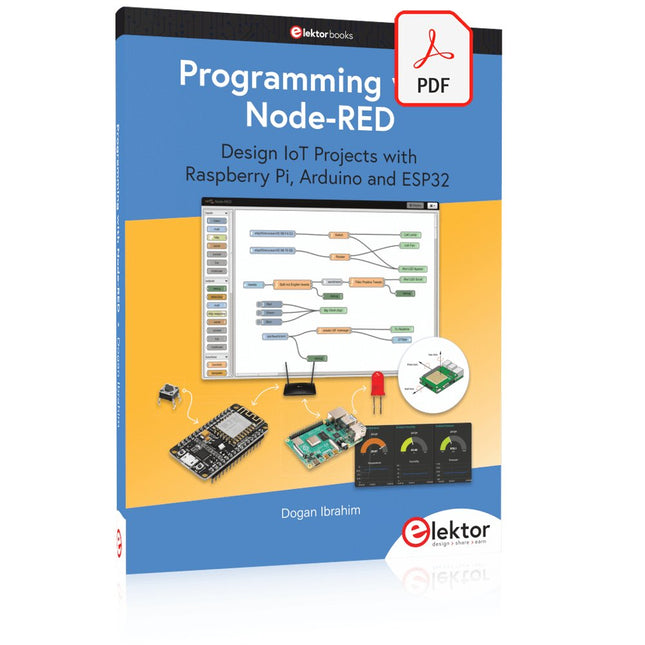
Elektor Digital Programming with Node-RED (E-book)
Design IoT Projects with Raspberry Pi, Arduino and ESP32 The Internet of Things (IoT) is becoming a major application area for embedded systems. As a result, more and more people are becoming interested in learning about embedded design and programming. Technical colleges and universities are moving away from legacy 8 and 16-bit microcontrollers and are introducing 32-bit embedded microcontrollers to their curriculums. Many IoT applications demand precision, high processing power, and low power consumption. Produced by IBM, Node-RED is an open-source visual editor for wiring the Internet of Things. Node-RED comes with a large number of nodes to handle a multitude of tasks. The required nodes are selected and joined together to perform a particular task. Node-RED is based on flow type programming where nodes are configured and joined together to form an application program. There are nodes for performing complex tasks, including web access, Twitter, E-mail, HTTP, Bluetooth, MQTT, controlling GPIO ports, etc. One particularly nice aspect of Node-RED is that the programmer does not need to learn how to write complex programs. For example, an email can be sent by simply joining nodes together and writing only a few lines of code. The aim of this book is to teach how Node-RED can be used in projects. The main hardware platform used with most of the projects in this book is Raspberry Pi 4. Chapters are included to show how Node-RED can be also be used with Arduino Uno, ESP32 DevKitC, and the ESP8266 NodeMCU microcontroller development boards.
€ 34,95
Members: € 31,46
-
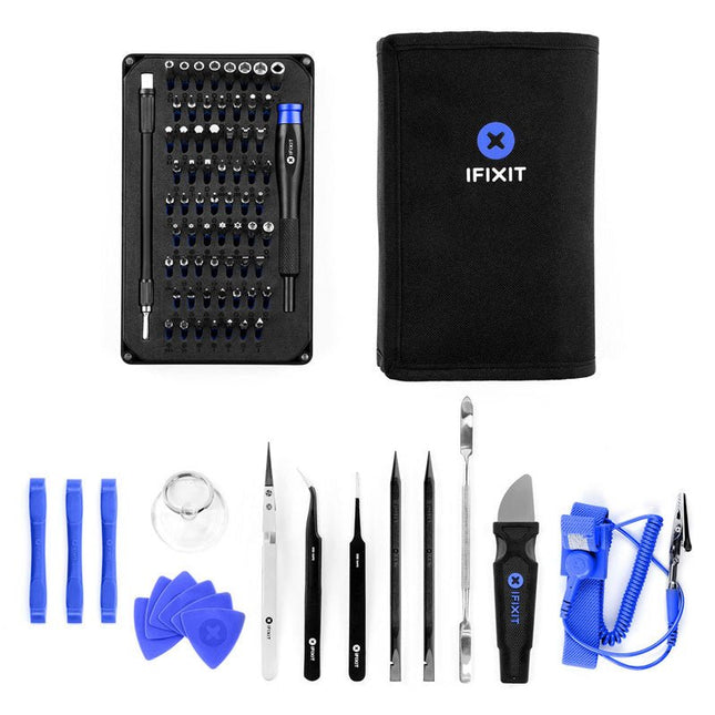
iFixit iFixit Pro Tech Toolkit
The Pro Tech Toolkit is the one thing every DIYer, fixer, hacker, hobbyist, and professional needs to tackle any job. Every tool in the Pro Tech Toolkit has been re-engineered to be better. From the 64 Bit Driver Kit to the iFixit Opening Picks, every tool is specially designed and selected to maximize your repair capabilities. At the core of this kit is the iFixit 64 Bit Driver Kit, designed with extensive research into what fastener types are currently used in the consumer electronics industry and which legacy fasteners are still in demand by consumers. From the Apple Watch with its new tiny Tri-Point screws to vintage Nintendo game consoles with gamebit fasteners, the 64 bit kit covers them all with the highest quality CNC machined bits. Even the sturdy case was carefully engineered, having no hinges or latches to break, and features a sorting tray inside the magnetically attached lid. High-Performance Toolkit for DIY Repairs The perfect toolkit for pros to average joes. Contains all the poking, prying, gripping, lifting, ESD safety, and screw driving tools needed to service consumer electronics. Completely re-engineered to provide all the tools that you need, and none that you don't. Included Anti-Static Wrist Strap – protection for circuits against static electricity Small Suction Handle – suction handle for holding onto things lacking handles 3x iFixit Opening Tool – soft plastic prying tools 6x iFixit Opening Picks – thin prying tool for opening electronic devices Nylon Tipped Reverse Tweezers – to elevate and hold your work Angled ESD Tweezers – ESD-safe, feature teeth for tougher grip Blunt ESD Tweezers – ESD-safe, feature teeth for tougher grip Standard Spudger – tough antistatic tool for a variety of purposes Halberd Spudger – features a hook for scooping, scraping, pulling, and guiding.ESD-safe. Metal Spudger – for more powerful prying, scraping, probing, and poking action Jimmy – handy tool for 'Jimmy'ing open electronics. Magnetic Pad – Holds tiny screws and parts during repairs Tool Roll – Durable and compact Mako Precision Bit Set – all the bits needed for repairs on small electronics Mako Precision Bit Set Includes 64 Bit Driver 150 mm Flex Extension 4 mm Screwdriver Bits Phillips – 000, 00, 0, 1, 2 Flathead – 1, 1.5, 2, 2.5, 3, 4 mm Torx – T2, T3, T4, T5 Torx Security – TR6, TR7, TR8, TR9, TR10, TR15, TR20, TR25 Pentalobe – P2, P5, P6 JIS – J000, J00, J0, J1 Hex – 0.7, 0.9, 1.3, 1.5, 2, 2.5, 3, 3.5, 4, 4.5, 5 mm Tri-point – Y000, Y00, Y0, Y1 Nut Driver – 2.5, 3, 3.5, 4, 4.5, 5, 5.5 mm Square – 1, 2 Gamebit – 3.8, 4.5 mm Spanner – 6, 8 Triangle – 2, 3 mm Standoff Bit for iPhone Oval Bit Magnetic Pickup Bit SIM Eject Bit 1/4" to 4 mm Driver Adapter
€ 69,95
-

Elektor Mai/Juin 2025 (FR)
Le téléchargement intégral de ce numéro est disponible pour nos membres GOLD et GREEN sur le site Elektor Magazine ! Pas encore membre ? Cliquez ici. PbMonitor v1.0Un système de surveillance des batteries pour les applications à onduleurs et de stockage d'énergie contrôleur de charge solaire avec MPPT (1)Principes de base d'un contrôleur de charge solaire pour les systèmes autonomes magnétomètre à intégration du champ et capteurs artisanaux exactitude, ou précision ?vos appareils doivent posséder les deux ! AD7124 : un C/AN de précision en pratiqueFeatures for Sensor Signal Conditioning outil de contrôle PIDOptimisez facilement vos paramètres embedded world 2025 démarrer en électronique...…contrôle de la tonalité Academy Pro BoxLivre + cours en ligne + matériel adaptateur Milliohm-mètreUtilisant la précision de votre multimètre Un nouveau jalon dans le domaine des semi-conducteursEn route vers le 1,4 nm Connecteurs à technologie traversanteLe meilleur des deux mondes : THR fréquencemètrePortable et auto-calibré par GPS compteurs analogiquesDrôles de composants, la série testeur de quartz autonomeQuelle est la précision de votre source d'horloge ? testeur I²C peu couteuxconnecter des appareils I²C directement à votre PC sur le vifbienvenue chez les Pt’tites 2025 : une odyssée de l'IAL'impact transformateur sur le développement de logiciels projet 2.0Corrections, mises à jour, et courrier des lecteurs synthétiseur MIDI autonome Raspberry Pi (2)Améliorons notre configuration avec l’Intelligence oscillateur à pont de Wien "nortonisé"Petite cause, grand effet tester un microcontrôleur à 0,10 $Le microcontrôleur CH32V003 RISC-V et MounRiver Studio en pratique un lecteur audio avec égaliseur basé sur un FPGA (2)Ajout d'un réglage du volume, d'un mixage avancé et d'une interface Web
€ 15,50
-
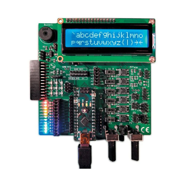
Elektor Labs Elektor Arduino Nano MCCAB Training Board
The Elektor Arduino Nano MCCAB Training Board contains all the components (incl. Arduino Nano) required for the exercises in the "Microcontrollers Hands-on Course for Arduino Starters", such as light-emitting diodes, switches, pushbuttons, acoustic signal transmitters, etc. External sensors, motors or assemblies can also be queried or controlled with this microcontroller training system. Specifications (Arduino Nano MCCAB Training Board) Power Supply Via the USB connection of the connected PC or an external power supply unit (not included) Operating Voltage +5 Vcc Input Voltage All inputs 0 V to +5 V VX1 and VX2 +8 V to +12 V (only when using an external power supply) Hardware periphery LCD 2x16 characters Potentiometer P1 & P2 JP3: selection of operating voltage of P1 & P2 Distributor SV4: Distributor for the operating voltagesSV5, SV6: Distributor for the inputs/outputs of the microcontroller Switches and buttons RESET button on the Arduino Nano module 6x pushbutton switches K1 ... K6 6x slide switches S1 ... S6 JP2: Connection of the switches with the inputs of the microcontroller Buzzer Piezo buzzer Buzzer1 with jumper on JP6 Indicator lights 11 x LED: Status indicator for the inputs/outputs LED L on the Arduino Nano module, connected to GPIO D13 JP6: Connection of LEDs LD10 ... LD20 with GPIOs D2 ... D12 Serial interfacesSPI & I²C JP4: Selection of the signal at pin X of the SPI connector SV12 SV9 to SV12: SPI interface (3.3 V/5 V) or I²C interface Switching output for external devices SV1, SV7: Switching output (maximum +24 V/160 mA, externally supplied) SV2: 2x13 pins for connection of external modules 3x3 LED matrix(9 red LEDs) SV3: Columns of the 3x3 LED matrix (outputs D6 ... D8) JP1: Connection of the rows with the GPIOs D3 ... D5 Software Library MCCABLib Control of hardware components (switches, buttons, LEDs, 3x3 LED matrix, buzzer) on the MCCAB Training Board Operating Temperature Up to +40 °C Dimensions 100 x 100 x 20 mm Specifications (Arduino Nano) Microcontroller ATmega328P Architecture AVR Operating Voltage 5 V Flash Memory 32 KB, of which 2 KB used by bootloader SRAM 2 KB Clock Speed 16 MHz Analog IN Pins 8 EEPROM 1 KB DC Current per I/O Pins 40 mA on one I/O pin, total maximum 200 mA on all pins together Input Voltage 7-12 V Digital I/O Pins 22 (6 of which are PWM) PWM Output 6 Power Consumption 19 mA Dimensions 18 x 45 mm Weight 7 g Included 1x Elektor Arduino Nano Training Board MCCAB 1x Arduino Nano
€ 79,95€ 69,95Best Price
-
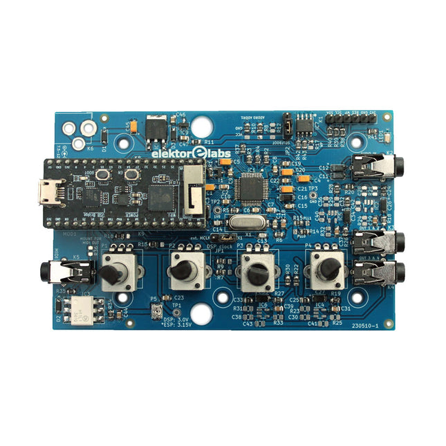
Elektor Labs Elektor Audio DSP FX Processor (New Revision)
The Elektor Audio DSP FX Processor combines an ESP32 microcontroller and an ADAU1701 Audio DSP from Analog Devices. Besides a user-programmable DSP core, the ADAU1701 has high-quality analog-to-digital and digital-to-analog converters built-in and features an I²S port. This makes it suitable as a high-quality audio interface for the ESP32. Programs for the ESP32 can be created with Arduino, Platform IO, CMake or by using the Espressif IDF in another way. Programs for the ADAU7101 audio DSPs are created with the free visual programming tool SigmaStudio by dragging and dropping pre-defined algorithm blocks on a canvas. Applications Bluetooth/Wi-Fi audio sink (e.g. loudspeaker) & source Guitar effect pedal (stomp box) Music synthesizer Sound/function generator Programmable cross-over filter for loudspeakers Advanced audio effects processor (reverb, chorus, pitch shifting, etc.) Internet-connected audio device DSP experimentation platform Wireless MIDI MIDI to CV converter and many more... Specifications ADAU1701 28-/56-bit, 50-MIPS digital audio processor supporting sampling rates of up to 192 kHz ESP32 32-bit dual-core microcontroller with Wi-Fi 802.11b/g/n and Bluetooth 4.2 BR/EDR and BLE 2x 24-bit audio inputs (2 V RMS, 20 kΩ) 4x 24-bit audio outputs (0.9 V RMS, 600 Ω) 4x Control potentiometer MIDI in- and output I²C expansion port Multi-mode operation Power supply: 5 V DC USB or 7.5-12 V DC (barrel jack, center pin is GND) Current consumption (average): 200 mA Included 1x ESP32 Audio DSP FX Processor board (assembled) 1x ESP32-PICO-KIT 2x Jumpers 2x 18-pin headers (female) 4x 10 KB potentiometers Downloads Documentation GitHub
€ 99,95€ 84,95Best Price
-

Elektor Digital Elektor 07-08/2022 (PDF)
Preiswerter Audio-MessplatzMit PC-Software und USB-Audio-Interface Netzspannungs-FrequenzmessgerätNetzfrequenz und -spannung überwachen Kleines InduktivitätsmessgerätEine erschwingliche Lösung für Ihr Heimlabor Reiten auf der SchallwelleEin Blick auf das Makerfabs Acoustic Levitation Kit Aller Anfang...muss nicht schwer sein: Dioden als Gleichrichter E-FFWD: Der Blick wieder nach vorn gerichtet! Erste Schritte mit dem OszilloskopFinden Sie den Weg durch den Knopf-und-Tasten-Dschungel Raspberry Pi Pico als Software Defined RadioFür das MSF-Zeitsignal Feuchtigkeitssensoren für GießanlagenAutomatische Bewässerung Umbruch in der Mess- und PrüftechnikInnovationen kleinerer Akteure Infografik 7-8/2022 Inspiration: Was wirklich wichtig istInterview mit dem Unternehmer Walter Arkesteijn von InnoFaith Beauty Sciences EMV-Störungen durch Speicherdrosseln minimieren Grafische Benutzeroberflächen mit Python:Tic-Tac-Toe Reed-RelaisBemerkenswerte Bauteile Einfaches analoges ESR-Messgerätmit Drehspulinstrument-Genauigkeit CO2-Ampel mit Sigfox-InterfaceVom WLAN unabhängig! Frauen in der Technik„Es geht nur so lange um Leistung, bis diese Leistung Titten hat.“ Low-Budget Tablet-Oszilloskop ADS1013DGutes Preis-/Leistungsverhältnis? Aufgeschraubt und reingeschaut: Wireless Smart PlugsSmarte Funksteckdosen mit ESP8266 & Co. Hautwiderstand und HautkapazitätKleine Experimente mit der menschlichen Hülle Aus dem Leben gegriffenDer Prophet gilt nichts im Vaterland Messgerät Pokit – die eierlegende Wollmilchsau?Klein und mit vielen Messmöglichkeiten HexadokuSudoku für Elektroniker
€ 11,90
-

Elektor Digital Elektor Mai/Juin 2023 (PDF)
Le téléchargement intégral de ce numéro est disponible pour nos membres GOLD et GREEN sur le site Elektor Magazine ! Pas encore membre ? Cliquez ici. Super Servo TesterTestez jusqu'à quatre servos, isolés ou in situ signaux analogiques et microcontrôleursCA/N, CN/A, mesure du courant, et plus Embedded World 2023 l'échantillonnage sub-Nyquist en pratiquecapture fiable des hautes fréquences à l'aide du sous-échantillonnage connecter un smartphone Android à un ESP32 ?projet pratique avec l'API wifi d'Android filtre actif 1 kHz pour mesures de distorsionmesures améliorées par l'optimisation du signal de mesure démarrer en électronique... multivibrations Projet 2.0corrections, mises à jour et messages de lecteurs le nouveau protocole I3Ceffet d?annonce ou vrai progrès BlueRC : télécommande IR avec smartphone et ESP32adaptative et universelle la documentation des microcontrôleurs sans peine (2)registres et schémas de principe automatisation des tests et des mesuresprogrammation de l'équipement d'essai pour qu'il fasse ce que vous voulez Infographie : test et mesure immunité contre les surtensionsprotection pour modules de puissance CC/CC non isolés appareil de mesure Wihatesteurs et compteurs d?installation sur lesquels vous pouvez compter automatisation des tests et partage des résultats sur le vifl?électronique des blocs enregistreur de données énergétiquesmesurer et enregistrer la consommation d'énergie assemblage du kit Rover M.A.R.S. de 4tronix disque de stationnement avec affichage e-papierune version informatisée innovante eCO? Telegram botmesureur de la qualité de l'air avec notification par Telegram les coulisses de l?audio haut de gamme maisonTon Giesberts d'Elektor interviewé sur l'art de la conception analogique visite à domicilenouvelle cible lecture d'étiquettes RFID et serrure de porte RFIDexemples de projets tirés du guide d'expérimentation pour Arduino d'Elektor Sondes de courant RF pour oscilloscopeLa mesure de courants RF sans peine pas pour les mauviettes - kit bras robotiqueavec Raspberry Pi Pico et MicroPython IA générativeMais qui a fait ça ? Hexadoku
€ 10,95
-

Elektor Digital Elektor Mei/Juni 2021 (PDF)
ZELFBOUW LIPO-SUPERCHARGER KITvan prototype tot productie ELEKTOR @ 60gedachten bij zestig jaar elektronica SIGLENT SDM3045X TAFELMULTIMETER DC-STROOMKLEMHall-sensor + ferrietkern + Arduino SOLDEERSTATION 2021makkelijk om te bouwen! KENNISMAKING MET DE PARALLAX PROPELLER 2 (DEEL 2)de ontwikkelomgeving en de code WIFI VOOR DE LORA SWITCHgeïntegreerd in Home Assistant met ESPHome GEEN ANGST VOOR DE CELLULAIRE MODULE! HOUD DE TIJD BIJ MET ESP32 EN TOGGLwerken met de M5Stack KENNISMAKING MET HET RASPBERRY PI PICO-BOARD EN DE RP2040 MICROPYTHON VOOR MICROCONTROLLERStechnieken voor kleine displays 12–200&NBSP;V DC/DC-CONVERTERvoor buizenversterkers WARMTEZOEKERde Seek Shot Pro warmtebeeldcamera OBJECTGEORIËNTEERD PROGRAMMERENeen korte inleiding met C++ OOST WEST LAB BEST...waar Kurt Diedrich synthesizers bouwt JAVA OP DE RASPBERRY PIdeel 1: GPIO’s DIP-SCHAKELAARSvreemde onderdelen INTERACTIEFcorrecties & updates || brieven van lezers WIENS PRODUCT IS HET EIGENLIJK?recht-op-reparatie beweging laat van zich horen UIT HET LEVEN GEGREPENhet grote blunderboek MICRO-PROFESSORassembleertaal leren op een Z80 ALLE BEGIN......hoeft niet zo moeilijk te zijn – zelfs als het om condensatoren gaat HEXADOKUThe Original Elektorized Sudoku
€ 9,95
-
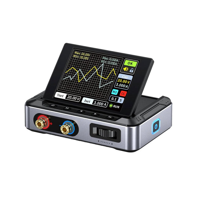
FNIRSI FNIRSI DPS150 DC Power Supply (150 W)
The FNIRSI DPS150 is a high-performance adjustable DC power supply that features a USB-C input interface and multiple power supply modes, allowing precise adjustment of output voltage (0-30 V) and current (0-5 A). It provides efficient, low-consumption, and stable output, equipped with multiple safety protection functions including overvoltage, overcurrent, overload, overheating, and reverse connection. It can be flexibly applied to serial connection of multiple devices, with rich and user-friendly display and operation, compact and portable design, meeting various application needs. Features 30 V, 5 A, 150 W variable DC power with 0.01 V, 0.001 A precision, CC/CV modes, and <20 mV ripple to protect sensitive electronics. Supports PC, QC, and DC inputs with programmable outputs and 6 preset voltage/current settings. Compatible with 4 mm banana plugs, U-shaped terminals, and copper wires for various equipment. 8 safety mechanisms including overvoltage, current, short circuit, and overheating protection. 2.8-inch HD IPS screen with 90° flip, numerical and curve displays for easy monitoring. Small, space-saving design for use in labs, repairs, and DIY projects. Specifications Input Voltage 5~32 V DC Input Current 100 mA-5 A Output Voltage 0-30 V Output Current 0~5 A Output Power 0-150 W Input Way PD fast charger QC fast charger Power bank DC power adapters Operating Environment 0-40°C Load Regulation 0.49% Full Load Efficiency 96.30% Display 2.8 inch (320 x 240) Dimensions 106 x 76 x 28 mm Weight 178 g Included 1x DPS150 Power Supply 2x Alligator clip wires (black & red) 1x Micro USB cable 1x Manual Downloads Manual Firmware V0.0.1
€ 59,00


