
Search results for "propscope OR usb OR oscilloscope OR 140193 OR 91"
-

FNIRSI FNIRSI FNB58 USB Tester (with Bluetooth)
The FNIRSI FNB58 USB tester (with Bluetooth) is a comprehensive and very accurate USB voltage and current meter. It features a 2.0-inch full-color HD TFT display, built-in USB-A, micro USB and USB-C interface. With this device you can measure the power supply or power consumption of products or the charging power of cell phones and power supplies. You can also determine the fast charging protocol of chargers. Features USB-A and USB-C interface 2.0" HD display Data at a glance Wide compatibility Ultra-precise data detection Play with fast charging technology Automatic protocol detection (PD2.0, 3.0, 3.1, PPS, QC2.0, 3.0, FCP, SCP, AFC, PE, DASH VOOC, SuperVOOC and more) Simple user interface, easy to operate 4 function curve displays (real-time voltage and current curve, offline curve recording, D+/D- voltage curve, high-speed power supply ripple measurement) Cable detection 10 groups of energy recording battery capacity calculation PC connectivity for data logging and firmware updates Bluetooth app for Android devices Specifications Voltage range 4-28 V Current range 0-7 A Power range 0-120 W Load equivalent internal resistance 0-9999.9 Ω D+/D- voltage 0-3.3 V Capacity 0-9999.99 Ah Power consumption 0-9999.99 Wh Cable resistance 0-9999.9 Ω Interfaces micro USB, USB-A, USB-C Dimensions 42 x 13 x 82 mm Downloads Manual Firmware V0.68
€ 49,95
-
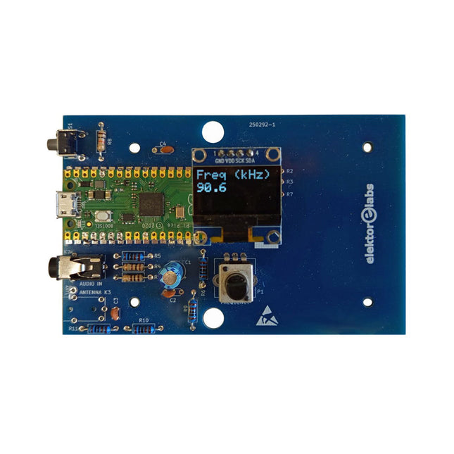
Elektor Labs Elektor AM Transmitter Kit
Build Your Own Vintage Radio Broadcaster The Elektor AM Transmitter Kit allows streaming audio to vintage AM radio receivers. Based on a Raspberry Pi Pico microcontroller module, the AM Transmitter can transmit on 32 frequencies in the AM band, from 500 kHz up to 1.6 MHz in 32 steps of approx. 35 kHz. The frequency is selected with a potentiometer and shown on a 0.96" OLED display. A pushbutton allows toggles the transmitting mode between On and Off. The range of the transmitter depends on the antenna. The onboard antenna provides a range of a few centimeters, requiring the AM Transmitter to be placed close to or inside the radio. An external loop antenna (not included) can be connected to increase the range. The Elektor AM Transmitter Kit comes as a kit of parts that you must solder to the board yourself. Features The board is compatible with a Hammond 1593N enclosure (not included).A 5 VDC power supply with micro-USB connector (e.g., an old phone charger) is needed to power the kit (not included). Current consumption is 100 mA. The Arduino software (requiring Earle Philhower’s RP2040 Boards Package) for the Elektor AM Transmitter Kit plus more information is available at the Elektor Labs page of this project. Component List Resistors R1, R4 = 100 Ω R2, R3, R8 = 10 kΩ R5, R6, R9, R10, R11 = 1 kΩ R7 = optional (not included) P1 = potentiometer 100 kΩ, linear Capacitors C1 = 22 µF 16V C2, C4 = 10 nF C3 = 150 pF Miscellaneous K1 = 4×1 pin socket K2, K3 = 3.5 mm socket Raspberry Pi Pico pushbutton, angle mount 0.96" monochrome I²C OLED display PCB 150292-1
€ 34,95€ 29,95Best Price
-

Elektor Academy Pro ESP32 by Example (Learning Course)
Complete ESP32 microcontroller learning course featuring a custom-designed MCU expansion board, hands-on projects, and a comprehensive online guide – perfect for learning hardware, programming, and connectivity step by step. A Practical Introduction to Embedded Systems with the ESP32 This course is designed for readers who are new to embedded systems and looking for a structured, example-driven way to get started. If you’ve explored general-purpose electronics or Arduino-based materials but found them too broad or lacking in practical guidance, this course offers a more focused alternative. Using the "ESP32 by Example Kit" (EEK) – a compact and affordable set of components featuring LEDs, sensors, an OLED display, and a motion processor – you’ll work with a consistent hardware setup throughout the course. Once assembled, the EEK stays mostly unchanged, allowing you to concentrate on learning and experimentation without constant reconfiguration. Topics include: Understanding and programming the ESP32 microcontroller Writing and deploying code with the Arduino IDE Exploring cyber-physical systems, culminating in basic drone control No prior experience with Arduino or embedded development is required. Each section features hands-on examples and mini-projects designed to reinforce key concepts and inspire deeper exploration. By the end of the course, you’ll be able not only to reproduce the book’s examples but also to build on them with your own ideas and applications. Whether you're interested in embedded programming, interactive systems, or introductory drone control, this course provides a clear and practical path to getting started. What you'll learn? Embedded programming with the ESP32 using the Arduino IDE Real-time sensor input and control via buttons, LEDs, and displays Gesture-based interaction using the MPU6050 motion sensor Bluetooth gamepad integration and drone control simulation Wi-Fi and UDP networking, local web servers, and NTP MQTT communication with cloud platforms like AWS and Arduino IoT How to build and deploy full-featured IoT systems Perfect for Students and self-learners exploring embedded systems Makers and IoT enthusiasts looking to improve their hardware skills Educators and trainers seeking ready-to-teach material Developers moving beyond Raspberry Pi or Arduino basics Support when you need it Access to instructors via Elektor Academy Helpful community forums and essential documentation What's inside the Box (Course)? New 384-page book: "ESP32 by Example" (valued at €45) Elektor ESP32 by Example Kit (EEK): Microcontroller Extension Board with 6 LEDs and 6 Buttons installed + OLED Display, MPU6050 3-axis Accelerometer and Gyroscope Module (valued at €40) Adafruit HUZZAH32 – ESP32 Feather MCU Board (valued at €30) ESP32 Cheap Yellow Display Board (valued at €25) DHT11 Humidity & Temperature Sensor Breadboard Jumper wires USB-C cable Access to the full course on the Elektor Academy Pro Learning Platform Instructional videos Downloadable Arduino project files for every module Learning Material (of this Box/Course) ▶ Click here to open Module 1 – Getting Started with the ESP32 & EEK Module 2 – Digital Output – LEDs and GPIO Module 3 – Switches and Input Handling Module 4 – EEK and PWM Module 5 – OLED and Display Output Module 6 – Motion Sensing with the MPU6050 Module 7 – Capstone Project (EEK in Action) Module 8 – WiFi and Web Control with ESP32 Module 9 – Cloud Concepts using EEK Module 10 – Hands-on: Arduino IoT Cloud and EEK Module 11 – BlueTooth and EEK GamePad Integration Module 12 – Why Drones? Module 13 – Drone Simulator Concepts Module 14 – Simple Drone Flight Control Module 15 – Real-Time Drone Flight Control Module 16 – Drone Control Mini-Projects Module 17 – Middleware and Python Scripting Module 18 – Python Applications for Drone Control Module 19 – Capstone EEK Control Project and Presentation About the Author Dr. Jim Solderitsch is an educator, software architect, systems developer, and cybersecurity researcher with a focus on cyber-physical systems. He currently serves as an Adjunct Professor in Computing Sciences at Villanova University in Pennsylvania. What is Elektor Academy Pro? Elektor Academy Pro delivers specialized learning solutions designed for professionals, engineering teams, and technical experts in the electronics and embedded systems industry. It enables individuals and organizations to expand their practical knowledge, enhance their skills, and stay ahead of the curve through high-quality resources and hands-on training tools. From real-world projects and expert-led courses to in-depth technical insights, Elektor empowers engineers to tackle today’s electronics and embedded systems challenges. Our educational offerings include Academy Books, Pro Boxes, Webinars, Conferences, and industry-focused B2B magazines – all created with professional development in mind. Whether you're an engineer, R&D specialist, or technical decision-maker, Elektor Academy Pro bridges the gap between theory and practice, helping you master emerging technologies and drive innovation within your organization.
€ 269,00€ 219,00Best Price
-

Rigol Rigol DSA815-TG Spectrum Analyzer (9 kHz – 1.5 GHz)
Highlights Frequency: 1.5 GHz DANL: -155 dBm Phase Noise: -80 dBc/Hz RBW: 10 Hz Tracking Generator Specifications All-Digital IF Technology Frequency Range from 9 kHz up to 1.5 GHz Min. -161 dBm Displayed Average Noise Level (Typ.) Min. < -98 dBc/Hz @ 10 kHz Offset Phase Noise Level Measurement Uncertainty < 0.8 dB 10 Hz Minimum Resolution Bandwidth Up to 1.5 GHz Tracking Generator Advanced Measurement Functions (Opt.) EMI Filter & Quasi-Peak Detector Kit (Opt.) VSWR Measurement Kit (Opt.) PC Software (Opt.) Optional RF TX/RX Training Kit Optional RF Accessories (Cable, Adaptor, Attenuator, Bridge ...) Complete Connectivity: LAN (LXI), USB Host & Device, GPIB (Opt.) 8 Inch WVGA (800x480) Display Compact Size, Light Weight Design Included 1x Rigol DSA815-TG Spectrum Analyzer 1x Power cord 1x USB cable
€ 974,66
-
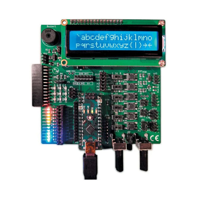
Elektor Labs Elektor Arduino Nano MCCAB Training Board
The Elektor Arduino Nano MCCAB Training Board contains all the components (incl. Arduino Nano) required for the exercises in the "Microcontrollers Hands-on Course for Arduino Starters", such as light-emitting diodes, switches, pushbuttons, acoustic signal transmitters, etc. External sensors, motors or assemblies can also be queried or controlled with this microcontroller training system. Specifications (Arduino Nano MCCAB Training Board) Power Supply Via the USB connection of the connected PC or an external power supply unit (not included) Operating Voltage +5 Vcc Input Voltage All inputs 0 V to +5 V VX1 and VX2 +8 V to +12 V (only when using an external power supply) Hardware periphery LCD 2x16 characters Potentiometer P1 & P2 JP3: selection of operating voltage of P1 & P2 Distributor SV4: Distributor for the operating voltagesSV5, SV6: Distributor for the inputs/outputs of the microcontroller Switches and buttons RESET button on the Arduino Nano module 6x pushbutton switches K1 ... K6 6x slide switches S1 ... S6 JP2: Connection of the switches with the inputs of the microcontroller Buzzer Piezo buzzer Buzzer1 with jumper on JP6 Indicator lights 11 x LED: Status indicator for the inputs/outputs LED L on the Arduino Nano module, connected to GPIO D13 JP6: Connection of LEDs LD10 ... LD20 with GPIOs D2 ... D12 Serial interfacesSPI & I²C JP4: Selection of the signal at pin X of the SPI connector SV12 SV9 to SV12: SPI interface (3.3 V/5 V) or I²C interface Switching output for external devices SV1, SV7: Switching output (maximum +24 V/160 mA, externally supplied) SV2: 2x13 pins for connection of external modules 3x3 LED matrix(9 red LEDs) SV3: Columns of the 3x3 LED matrix (outputs D6 ... D8) JP1: Connection of the rows with the GPIOs D3 ... D5 Software Library MCCABLib Control of hardware components (switches, buttons, LEDs, 3x3 LED matrix, buzzer) on the MCCAB Training Board Operating Temperature Up to +40 °C Dimensions 100 x 100 x 20 mm Specifications (Arduino Nano) Microcontroller ATmega328P Architecture AVR Operating Voltage 5 V Flash Memory 32 KB, of which 2 KB used by bootloader SRAM 2 KB Clock Speed 16 MHz Analog IN Pins 8 EEPROM 1 KB DC Current per I/O Pins 40 mA on one I/O pin, total maximum 200 mA on all pins together Input Voltage 7-12 V Digital I/O Pins 22 (6 of which are PWM) PWM Output 6 Power Consumption 19 mA Dimensions 18 x 45 mm Weight 7 g Included 1x Elektor Arduino Nano Training Board MCCAB 1x Arduino Nano
€ 79,95€ 69,95Best Price
-
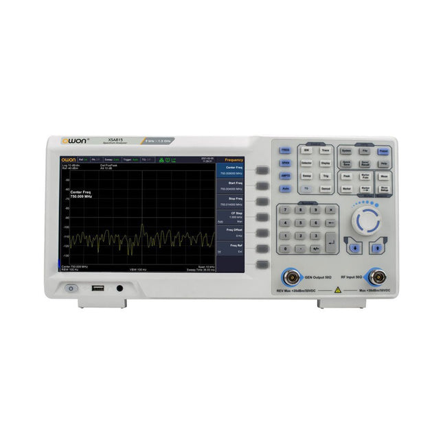
OWON OWON XSA815-TG Spectrum Analyzer (9 kHz – 1.5 GHz)
The OWON XSA815-TG (9 kHz-1.5 GHz) is a cost effective spectrum analyzer with tracking generator included and a frequency resolutions of 1 Hz. Features Frequency Range from 9 kHz to 1.500009 GHz 9-inch display 9 kHz to 1 MHz -95 dBm Displayed Average Noise Level, 1 MHz to 500 MHz 140 dBm (Typical), <-130 dBm Phase Noise -10 kHz <-80 dBc/Hz 100 kHz <-100 dBc/Hz 1 MHz <-115 dBc/Hz Resolution Bandwidth (-3 dB): 1 Hz to 1 MHz, in 1-3-5-10 sequence Tracking Generator Kit: 100 kHz to 1.500009 GHz Specifications Frequency Range 9 kHz to 500.009 MHz Frequency Resolution 1 Hz Frequency Span 9 kHz to 1.500009 GHz Span Range 0 Hz, 100 Hz to max frequency of instrument Span Uncertainty ±span / (sweep points-1) SSB Phase Noise (20°C to 30°C, fc=1 GHz) Carrier Offset 10 kHz <-80 dBc/Hz | 100 kHz <-100 dBc/Hz | 1 MHz <-115 dBc/Hz Resolution Bandwidth (-3 dB) 1 Hz to 1 MHz, in 1-3-5-10 sequence RBW Accuracy <5% typical Resolution Filter Shape Factor (60 dB: 3 dB) <5 typical Video Bandwidth (-3 dB) 10 Hz to 1 MHz, in 1-3-5-10 sequence Amplitude measurement range DANL to +10 dBm, 100 kHz to 10 MHz, Preamp Off DANL to +20 dBm, 10 MHz to 1.5 GHz, Preamp Off Reference Level -80 dBm to +30 dBm, 0.01dB by step Preamp 20 dB, nominal, 100 kHz to 1.5 GHz Input Attenuator 0 to 40 dB, 1 dB by step Display Average Noise Level Input attenuation = 0 dB, RBW = VBW = 100 Hz, sample detector, trace average ≥ 50, 20°C to 30°C, input impedance = 50 Ω) Preamp Off 9 kHz to 1 MHz -95 dBm (Typical), <-88 dBm Preamp Off 1 MHz to 500 MHz -140 dBm (Typical), <-130 dBm Preamp On 100 kHz to 1 MHz -135 dBm (Typical), <-128 dBm Preamp On 1 MHz to 500 MHz -160 dBm (Typical),<-150 dBm Tracking Generator (optional) Frequency Range 100 kHz to 1.500009 GHz Output power level range -40 dBm to 0 dBm Output level resolution 1 dB Output flatness Relative to 50 MHz | ±3 dB Tracking generator spurious Harmonic spurious -30 dBc (Tracking generator output power -10 dBm) Non-harmonic spurious -40 dBc (Tracking generator output power -10 dBm) Tracking generator to input terminal isolation -60 dB (Tracking generator output power 0 dBm) Tracking generator to input terminal isolation -60 dB (Tracking generator output power 0 dBm) Tracking generator to input terminal isolation -60 dB (Tracking generator output power 0 dBm) Dimensions 375 x 185 x 120 mm Weight 3.7 kg Included 1x XSA815-TG 1x 220 V AC power cord 1x USB Cable 1x Quickstart guide Downloads Quick Guide Specifications
€ 907,50
-

Red Pitaya Red Pitaya STEMlab 125-14 PRO Gen 2 Starter Kit (incl. Book)
This bundle includes the Red Pitaya STEMlab 125-14 PRO Gen 2 Starter Kit and the new book "Experimenting with Red Pitaya STEMlab Gen 2". The Red Pitaya STEMlab 125-14 PRO Gen 2 Starter Kit is a powerful and flexible platform for signal processing, data acquisition, and electronic measurement applications. Designed for engineers, developers, researchers, and educators, this kit provides everything required to start building advanced measurement and control systems. At the core of the kit is the STEMlab 125-14 PRO Gen 2 board, an upgraded and ultra-lightweight development platform. Powered by the Xilinx Zynq-7010 SoC with 512 MB of RAM, it combines FPGA programmability with ARM processing power to enable high-performance instrumentation and custom signal-processing solutions. The board offers 14-bit ADC and DAC resolution, a 125 MS/s sampling rate, an input range of ±20 V, and up to 60 MHz bandwidth. Its improved low-noise analog front-end, USB-C connectivity, and compact design make it suitable for demanding applications such as RF development, radar systems, photonics research, software-defined radio (SDR), and industrial automation. The Starter Kit includes all essential accessories for immediate use: a microSD card with preinstalled operating system, power supply, Ethernet cable for remote access, two 100 MHz oscilloscope probes, and SMA-to-BNC adapters for flexible signal connections. The Red Pitaya STEMlab 125-14 PRO Gen 2 Starter Kit is an excellent platform for rapid prototyping, FPGA development, measurement instrumentation, and advanced electronics experimentation. Features 14-bit ADC and DAC resolution 125 MS/s sampling rate ±20 V input range Up to 60 MHz bandwidth Xilinx Zynq-7010 SoC (FPGA + ARM processor) 512 MB RAM Low-noise analog front- and back-ends Applications RF development and testing Radar and wireless systems Software-defined radio (SDR) Photonics and optical research Industrial automation and control systems Signal analysis and instrumentation Rapid prototyping of electronic measurement systems Specifications Processor Dual-core ARM Cortex-A9 FPGA AMD Xilinx Zynq-7010 SoC RAM 512 MB (4 Gb) Storage microSD card (up to 32 GB) Operating System Linux-based Red Pitaya OS ADC Resolution 14-bit DAC Resolution 14-bit Bandwidth 60 MHz (DC) Sampling Rate 125 MS/s Analog Input Channels 2 Analog Output Channels 2 Input Voltage Range ±1 V (LV) / ±20 V (HV) Input Impedance 1 MΩ / 10 pF Output Voltage Range ±1 V Ethernet 1x Gigabit Ethernet (RJ45) USB 2x USB-C 2.0 (for power and console) Digital I/O 16x GPIO (3.3 V) Communication Interfaces I²C, SPI, UART, CAN Power Supply 5 V/3 A via USB-C Dimensions 106.8 x 60.0 x 17.9 mm Included 1x Red Pitaya STEMlab 125-14 PRO Gen 2 board 2x 100 MHz oscilloscope probes 2x SMA-to-BNC adapters 1x microSD card with preinstalled OS 1x USB-C Power supply 1x Ethernet cable Downloads Documentation Schematics Book: Experimenting with Red Pitaya STEMlab Gen 2 With this new book, Red Pitaya goes beyond a versatile board. It becomes a powerful laboratory instrument for precision measurement, analysis, and control. From the fundamentals of electronic project development, monitoring, control, and design to testing, this book walks you step-by-step through everything you need to know to harness the full potential of Red Pitaya hardware and software. The book presents real-time, FPGA-based projects that are developed on a PC using the Vivado environment, then transferred to the Red Pitaya for execution and testing. You will learn about enhanced performance, expanded I/O capabilities, improved FPGA features, and advanced connectivity options that open up new frontiers for precision measurement, monitoring, and control in your embedded applications. Inside the book you will discover: A deep dive into Red Pitaya architecture and hardware design Electronic experiments using Red Pitaya for measurement and monitoring Hands-on projects using the Python programming language Practical guidance for FPGA programming using Red Pitaya Red Pitaya FPGA projects using the Verilog HDL under Vivado IDE Practical design of electronic projects including measurement and testing Step-by-step examples that bridge theory and real-world implementation Whether you are designing your own electronic circuits, developing signal analysis tools, or creating real-time control or monitoring systems, this book provides you the knowledge and confidence you need to fully learn and customize the Red Pitaya platform.
€ 799,00
Best Price
-
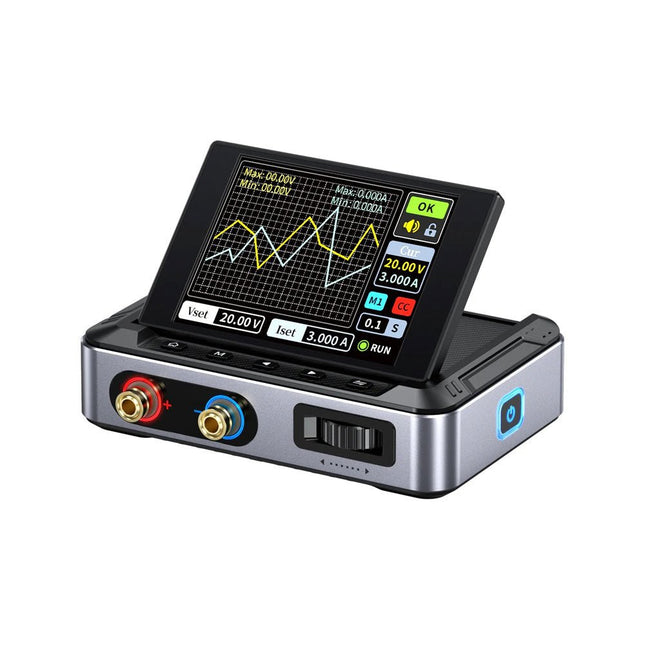
FNIRSI FNIRSI DPS150 DC Power Supply (150 W)
The FNIRSI DPS150 is a high-performance adjustable DC power supply that features a USB-C input interface and multiple power supply modes, allowing precise adjustment of output voltage (0-30 V) and current (0-5 A). It provides efficient, low-consumption, and stable output, equipped with multiple safety protection functions including overvoltage, overcurrent, overload, overheating, and reverse connection. It can be flexibly applied to serial connection of multiple devices, with rich and user-friendly display and operation, compact and portable design, meeting various application needs. Features 30 V, 5 A, 150 W variable DC power with 0.01 V, 0.001 A precision, CC/CV modes, and <20 mV ripple to protect sensitive electronics. Supports PC, QC, and DC inputs with programmable outputs and 6 preset voltage/current settings. Compatible with 4 mm banana plugs, U-shaped terminals, and copper wires for various equipment. 8 safety mechanisms including overvoltage, current, short circuit, and overheating protection. 2.8-inch HD IPS screen with 90° flip, numerical and curve displays for easy monitoring. Small, space-saving design for use in labs, repairs, and DIY projects. Specifications Input Voltage 5~32 V DC Input Current 100 mA-5 A Output Voltage 0-30 V Output Current 0~5 A Output Power 0-150 W Input Way PD fast charger QC fast charger Power bank DC power adapters Operating Environment 0-40°C Load Regulation 0.49% Full Load Efficiency 96.30% Display 2.8 inch (320 x 240) Dimensions 106 x 76 x 28 mm Weight 178 g Included 1x DPS150 Power Supply 2x Alligator clip wires (black & red) 1x Micro USB cable 1x Manual Downloads Manual Firmware V0.0.1
€ 59,00
-
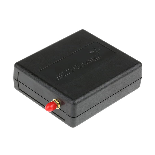
SDRplay SDRplay RSP1B 14-bit SDR Receiver (1 kHz to 2 GHz)
The SDRplay RSP1B is an enhanced version of the popular RSP1A – a powerful, wideband, full-featured 14-bit SDR that covers the RF spectrum from 1 kHz to 2 GHz. The RSP1B comes in a rugged, black-painted steel case and offers significantly improved noise performance. All it needs is a computer and an antenna to deliver excellent communications-receiver functionality. It includes a choice of SDRuno for Windows and the multi-platform SDRconnect software for Windows, macOS, and Linux (supplied free of charge by SDRplay). You can monitor up to 10 MHz of spectrum at a time. A documented API allows developers to create new demodulators or applications for the platform. Features Covers all frequencies from 1 kHz through VLF, LF, MW, HF, VHF, UHF and L-band to 2 GHz, with no gaps Receive, monitor and record up to 10 MHz of spectrum at a time Free use of windows-based SDRuno software which provides an ever-increasing feature-set Strong and growing software support network Calibrated S meter/ RF power and SNR measurement with SDRuno (including datalogging to .CSV file capability) Documented API provided to allow demodulator or application development on multiple platforms Excellent dynamic range for challenging reception conditions Works with popular 3rd party SDR software (including HDSDR, SDR Console and Cubic SDR) ExtIO based plugin available Software upgradeable for future standards Strong and growing software support network API provided to allow demodulator or application development Multiplatform driver and API support including Windows, Linux, Mac, Android and Raspberry Pi Up to 16 individual receivers in any 10 MHz slice of spectrum using SDRuno Calibrated S meter and power measurements with SDRuno Stand-alone windows-based spectrum analyser software available (with sweep, sample and hold features) Ideal for monitoring of ISM/ IoT/ Telemetry bands <2 GHz Ideal for portable operation Specifications Frequency Range 1 kHz – 2 GHz Antenna Connector SMA Antenna Impedance 50 Ohms Current Consumption (Typical) 185 mA (excl. Bias-T) USB Connector USB Type B Maximum Input Power +0 dBm Continuous+10 dBm Short Duration ADC Sample Rates 2-10.66 MSPS ADC Number of Bits 14 bit 2-6.048 MSPS12 bit 6.048-8.064 MSPS10 bit 8.064-9.216 MSPS8 bit >9.216 MSPS Bias-T 4.7 V100 mA guaranteed Reference 0.5ppm 24 MHz TCXO.Frequency error trimmable to 0.01ppm in field. Operating Temperature Range -10˚C to +60˚C Dimensions 98 x 88 x 34 mm Weight 110 g Downloads Datasheet Software RSP1B vs RSPdx vs RSPduo RSP1B RSPdx RSPduo Continuous coverage from 1 kHz to 2 GHz ✓ ✓ ✓ Up to 10 Mhz visible bandwidth ✓ ✓ ✓ 14-bit ADC silicon technology plus multiple high-performance input filters ✓ ✓ ✓ Software selectable AM/FM & DAB broadcast band notch filters ✓ ✓ ✓ 4.7 V Bias-T for powering external remote antenna amplifier ✓ ✓ ✓ Powers over the USB cable with a simple type B socket ✓ ✓ ✓ 50Ω SMA antenna input(s) for 1 kHz to 2 GHz operation (software selectable) 1 2 2 Additional software selectable Hi-Z input for up to 30 Mhz operation ✓ Additional software selectable 50Ω BNC input for up to 200 MHz operation ✓ Additional LF/VLF filter for below 500 kHz ✓ 24 MHz reference clock input (+ output on RSPduo) ✓ ✓ Dual tuners enabling reception on 2 totally independent 2 MHz ranges ✓ Dual tuners enabling diversity reception using SDRuno ✓ Robust and strong plastic case (with internal RF shielding layer) ✓ Rugged black painted steel case ✓ ✓ Overall performance below 2 MHz for MW and LF + ++ + Multiple simultaneous applications + + ++ Performance in challenging fading conditions (*using diversity tuning) + + *++
€ 148,99
-
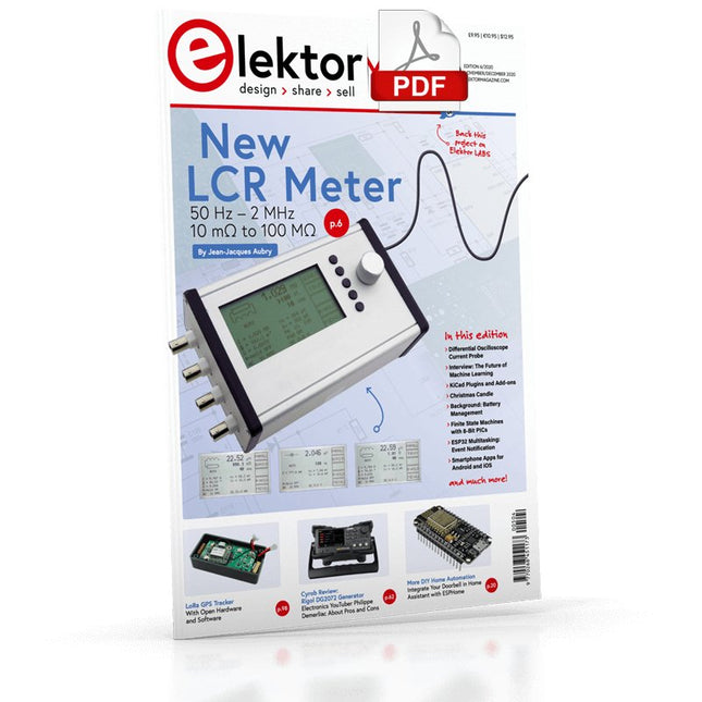
Elektor Digital Elektor November/December 2020 (PDF) EN
New LCR Meter 50 Hz - 2 MHz Part 1automatic impedance measuring bridge measures the resistance, capacitance and inductance of components with an impedance of 10 mΩ to 100 MΩ From Ding-Dong Door Chime to IoT DoorbellIntegrate your doorbell in Home Assistant with ESPHome Battery ManagementWhat to Be Aware of When Using (Lithium) Batteries Starting Out in ElectronicsEasier Than Imagined! Small Circuits RevivalFrom the Elektor Suggestions Box Breadboard Graphics with Fritzing Analogue Filter Design (Part 2)Active Filters Homelab Tours: The Lap CounterA Project for Mini Petrol-Heads Developer’s ZoneTips & Tricks, Best Practices and Other Useful Information Review: Rigol DS1054Z Four-Channel Oscilloscope Christmas CandleBlow It Out! Tunable Valve Sinewave Generator Retro is back! Review: The Rigol DG2072 Generator KiCad Plugins and Add-ons Differential Oscilloscope Current Probe 2.0Measure Currents Using Your Oscilloscope The Hewlett-Packard Interface LoopConnect the world! The Future of Machine LearningAn Interview with Daniel Situnayake Smartphone Apps for Android and iOSProgramming Apps Within a Single Development Environment From Life's ExperienceThe Value of a Technical Education 5G: How Infrastructure Shapes Our Society Practical ESP32 Multitasking (5)Task event notification HP 10811 OscillatorPeculiar Parts, the series LoRa GPS TrackerWith Open Hardware and Software Programming the Finite State Machinewith 8-bit PICs in Assembly and C
€ 7,50
-

Elecrow Elecrow ThinkNode M5 – Meshtastic LoRa Transceiver (868 MHz)
High-Performance LoRa Communication Device The Elecrow ThinkNode M5 is a compact, portable LoRa communication device designed for off-grid messaging, location sharing, and outdoor use. Powered by an ESP32-S3 processor and an SX1262 LoRa chip, it comes pre-installed with Meshtastic firmware and can be configured conveniently via Bluetooth using the official Meshtastic app. The integrated multi-GNSS module supports GPS, GLONASS, BeiDou, and QZSS for reliable positioning and location sharing. Messages and device information are displayed on the energy-efficient 1.54-inch e-paper screen, while the built-in 1,200 mAh rechargeable battery enables extended mobile operation. With its integrated LoRa antenna, compact housing, RTC, and support for both Meshtastic and MeshCore firmware, the ThinkNode M5 is a practical communication solution for hiking, camping, remote locations, and emergency situations where conventional mobile networks are unavailable. Features LoRa communication Multi-GNSS positioning 1,200 mAh rechargeable battery 1.54-inch e-paper display Built-in RTC Compatible with MeshCore Compatible with Meshtastic Specifications Main Processor (ESP32-S3) CPU/SoC Xtensa 32-bit LX7 dual-core processor, clocked at up to 240 MHz System Memory 512 KB SRAM, 8 MB PSRAM Storage 4 MB Flash, 384 KB ROM Firmware Meshtastic firmware is fully compatible, and the signal is transmitted in LoRa mode EPD (Electronic Paper Display) Display Size 1.54 inch EPD (monochrome Ink screen) Display Materials E-lnk (Electronic Ink) Resolution 200 x 200 Driver Chip SSD1681 (via SPI or I²C interface) Global Fresh Time 2s Wireless Communication Bluetooth Bluetooth Low Energy and Bluetooth 5.0 (phone configuration) LoRa SX1262 LoRa Module, EU 868 MHz(external antenna) Hardware Interfaces USB-C, RP-SMA Function GPS Location (GPS, GLONASS, BeiDou, QZSS), EPD Display, RTC, USB 2.0, PMU power management (built-in 1200 mAh lithium battery), buzzer, etc. Button Knob Switch, Function Button, Page Turn Button, GPS Switch, Reset Button LED Indicator Power supply, GPS/LoRa indication Others Power Input 5 V/1 A, supports USB or lithium battery power supply Power consumption The maximum working current is about 340 mA (CPU + LoRa module), and the low power consumption is about 34 uA Operating Temperature -10~50°C Storage Temperature -20~60°C Relative humidity 10-95%, @ 40°C (non-condensing) Enclosure ABS Plastic Dimensions 82 x 51.6 x 26.3 mm Weight 81 g Included 1x Elecrow ThinkNode M5 1x LoRa antenna 1x USB-C cable 1x Manual Downloads Manual
€ 74,95
Members: € 67,46
-

FNIRSI FNIRSI HRM-10 Battery Internal Resistance & Voltage Tester
The FNIRSI HRM-10 is a portable, high-precision battery internal resistance and voltage tester. This device offers true four-wire measurement and is designed for both accuracy and ease of use. It automatically measures internal resistance and voltage values simultaneously, displaying the results on its HD color screen. Users have the option to manually adjust voltage and resistance ranges to suit their needs. The device also includes a sorting mode that automatically filters the good and bad batteries based on user-set thresholds. Additionally, it supports the storage of historical data and allows for exporting measurement records in table format. Features High Measurement Accuracy Tabular Data Export Auto-Evaluate Measurement Results 8 Threshold Settings HD Color Screen Folding Stand 1000 mAh Lithium Battery Specifications Voltage Resistance Measuring range 0-100 V (DC) 0-200 Ω Accuracy ±0.5% ±0.5% Gear Automatic, 1 V, 10 V, 100 V Automatic, 20 mΩ, 200 mΩ, 2 Ω, 20 Ω, 200 Ω Instrument test signal frequency 1 Khz (AC) Rechargeable USB-C (5 V/1 A) Built-in battery 1000 mAh lithium battery User calibration Yes Sorting mode Yes History record Yes Recorded data export Yes Working environment –10°C to +45°C, relative humidity <80% Storage environment –20°C to +80°C, relative humidity <80% Dimensions 158.7 x 80.5 x 28.4 mm Weight 225 g Included 1x FNIRSI HRM-10 Internal Resistance Tester 1x Clip Test Line 1x USB-C data cable 1x Manual Downloads Manual Firmware V0.3
€ 49,95


