
Search results for "joy OR it OR sensor OR kit OR x40"
-
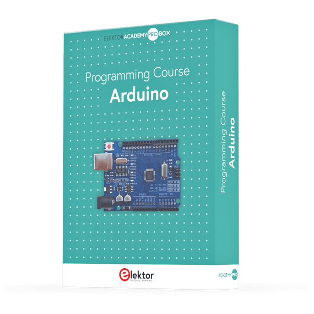
Elektor Academy Pro Arduino (Programming Course)
This complete Arduino Uno-based microcontroller programming course features a textbook, a component kit, hands-on projects, and a comprehensive online course with simulations. It is ideal for step-by-step learning of embedded systems programming with Arduino using a practical, hands-on approach. A Practical Introduction to Embedded Systems with the Arduino Uno This course is designed for people who are new to embedded systems and looking for a structured, example-driven way to get started. A kit of parts comprising LEDs and resistors, switches, sensors and actuators, displays, a breadboard and wires, and more is included. These are used in the course to illustrate example applications. No prior experience with Arduino or embedded development is required. Each section features hands-on examples and mini projects designed to reinforce key concepts and inspire deeper exploration. By the end of the course, you’ll be able not only to reproduce the examples but also to build on them with your own ideas and applications. What Will You Learn? Microcontroller programming with Arduino using the Uno R3 board Working with Digital I/O, read buttons and encoders, control LEDs and relays Read analog inputs, voltages, and analog sensors Generating analog output signals and PWM Use serial communication like UART, I²C and SPI to control displays and read digital sensors and SD cards Managing time Working with interrupts Real-time sensor input and control via buttons, LEDs, and displays Control actuators like relays and servo motors Who Is It For? Students and self-learners exploring embedded systems Makers and IoT enthusiasts looking to improve their hardware skills Educators and trainers seeking ready-to-teach material What's Inside the Box? Access to the full course on the Elektor Academy Pro Learning Platform Uno R3 microcontroller board + USB cable Book: Programming Microcontrollers in C/C++ Using Arduino Downloadable project files for every module Component Box: 2× LED, red, 5 mm LED, green, 5 mm 3× Resistor, 470 Ω, 0.25 W LDR Potentiometer, 10 kΩ, linear Pushbutton Rotary encoder module Relay module DHT22 Humidity & Temperature Sensor TM1637-compatible 4-digit 7-segment display MPU-6050 IMU with headers SSD1306-compatible I²C OLED display Micro SD card adapter with header Buzzer SG90 Micro Servo ILI9341-compatible SPI 240×320 TFT display 20× Jumper wires Breadboard All Programming Courses (and differences in content) Course Arduino Raspberry Pi Pico with Arduino C/C++ ESP32 with Arduino C/C++ Raspberry Pi Pico with MicroPython ESP32 with MicroPython Online Course Access to Arduino Course Access to Pico with Arduino C/C++ Course Access to ESP32 with Arduino C/C++ Course Access to Pico with MicroPython Course Access to ESP32 with MicroPython Course Board Uno R3 Raspberry Pi Pico ESP32 Raspberry Pi Pico ESP32 Book Programming Microcontrollers in C/C++ Using Arduino Programming Microcontrollers in C/C++ Using Arduino Programming Microcontrollers in C/C++ Using Arduino Programming Microcontrollers in MicroPython Programming Microcontrollers in MicroPython Kit 40-piece Component Box 40-piece Component Box 40-piece Component Box 40-piece Component Box 40-piece Component Box
€ 69,95
Members: € 62,96
-
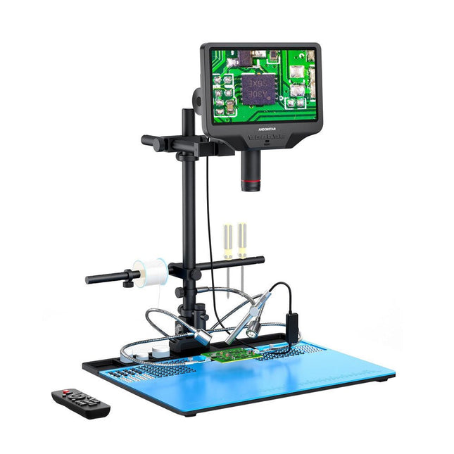
Andonstar Andonstar AD409 Max-ES 10.1" HDMI Digital Microscope (incl. Endoscope)
The Andonstar AD409 Max-ES boosts a high-quality metal lens and a unique UV filter design. Crafted from top-tier industrial-grade materials, it delivers unmatched precision and durability, ensuring a reliable product experience. The UV filter positioned in front of the metal lens blocks soldering heat, smoke, and dust, safeguarding the lens and making it perfect for soldering and maintenance professionals. The AD409 Max-ES features an oversized Max station (46 x 37 x 47.5 cm) and an advanced tool set, expanding the soldering station area by 370%. This upgrade meets the demands of professional soldering tasks and provides ample workspace for larger projects. The easy-to-use tool holder keeps tools within reach, ensuring they are always accessible. Additionally, the soldering helping hands with rotatable clamps simplify soldering and repair tasks, enhancing efficiency and convenience. The endoscope offers an all-around 360° view. This allows for clear observation of components from all sides and inside pipes, eliminating blind spots and ensuring thorough inspections. Features High-quality Metal Lens and Unique UV Filter Design New Max station Easy-to-use Tool Holder and Soldering Helping Hands Microscope with Endoscope All-around View 360° Professional HDMI Digital Microscope supports Multiple Output Methods 8 Levels adjustable LEDs Convenient Wireless Remote Control Specifications Screen size 10.1 inch (1280x800) Image sensor 4 MP Video output UHD 2880x2160 (24fps)FHD 1920x1080 (60fps/30fps)HD 1280x720 (120fps) Video format MP4 Magnification Up to 300 times (27 inch HDMI monitor) Photo resolution Max. 24 MP (5600x4200) Photo format JPG Focus range Min. 5 cm Frame Rate Max. 120fps Video interface HDMI Storage microSD card (up to 64 GB) PC support Windows, PC software with measurement Mobile phone, tablet terminal support Support WiFi connection and measurement Power source 5 V DC Light source 2 LEDs with the stand Endoscope Yes Stand size 46 x 37 x 47.5 cm (18.1 x 14.6 x 18.7") Included 1x Andonstar AD409 Max-ES Digital Microscope 1x Endoscope 1x Stand with 2 LEDs 1x UV filter (already assembled in the lens) 1x Soldering mat 1x Beam 1x Column 1x Tool holder 1x Soldering Helping Hands 1x Power adapter 1x Power cable 1x HDMI cable 1x USB cable 1x IR remote 1x Manual Downloads Manual Software
€ 399,00€ 339,00Best Price
-

Elektor Labs Elektor Low-Noise Lab Power Supply
The Elektor Low-Noise Lab Power Supply is a fully analogue, adjustable, medium-power symmetrical bench supply that contains no switching or digital components. It provides an output voltage adjustable between 0 V and ±22 V, and an output current adjustable from 0 A to 1 A. Because it avoids any form of switching circuitry, the design delivers extremely low noise. To display both output voltages and currents, four miniature moving-coil panel meters are used. Most modern laboratory power supplies and AC adapters employ switch-mode techniques. Even the best examples inevitably exhibit high-frequency ripple and other switching artefacts on their output, which can interfere with the testing of sensitive analogue circuits and disturb low-level measurements. To overcome this, the concept here is a completely analogue power supply. Although less efficient than its switch-mode counterparts, the reduced efficiency is of little importance for test-bench use and ensures cleaner, more reliable measurement results. Because many analogue circuits require a symmetrical supply, this design delivers positive and negative output voltages of equal magnitude. A small amount of adjustment is available to compensate for any imbalance. Naturally, a variable current-limit function is also included. The kit includes the components required to build the power supply, except for the transformers. Specifications Output Voltage 0…+22 V, 0, −22 V Output Current 0…+1 A, 0…−1 A Noise −85 dBV, (at 0.95 A/20 V, B = 22 kHz) −84 dBV (at 0.95 A/20 V, B > 500 kHz) Ripple 50 µVRMS (at 950 mA/20 V, B = 22 kHz, mainly 100 Hz component) Included 3x PCBs: Regulator (PCB-1), Mains Filter (PCB-2) and Transformer (PCB-3) All the components except the AC transformers 4x moving-coil meters Additional parts for wiring (wires, banana sockets, IEC Power entry module, etc.) Not included The three AC transformers An enclosure Parts List For the Regulator PCB (240386-1) Resistors (250 mW, 1%) R1 = 12 Ω R2, R8, R37, R62 = 1 MΩ R3, R7, R10, R13, R17, R20, R22, R30, R35, R42, R45, R47, R55, R60 = 100 Ω, 600 mW R4, R5 = 4.7 kΩ R6 = 100 kΩ R9, R12, R14, R36, R38, R39, R61, R63, R66, R72, R78, R79 = 10.0 kΩ, 600 mW R11 = 9.76 kΩ, 600 mW R15, R40 = 44.2 kΩ, 600 mW R16, R41, R77 = 1 kΩ R18, R43 = 1.5 kΩ, 1 W, 5% R19, R44 = 470 Ω, 1 W, 5% R21, R46 = 330 Ω, 600 mW R23, R24, R48, R49 = 1.0 Ω, 1 W R25, R50 = 1 kΩ, 1 W, 5% R26, R28, R51, R53 = 1.000 kΩ 0.1%, 15 ppm/C R27, R29, R52, R54 = 10.00 kΩ 0.1%, 15 ppm/C R31, R56 = 1.2 kΩ, 1 W, 5% R32, R57 = 47 kΩ R33, R58 = 270 Ω R34, R59 = 27 kΩ R64, R69 = 12.0 kΩ R65 = 3.0 kΩ, 600 mW R67, R80 = 470 Ω, 600 mW R68, R70 = 6.8 kΩ, 600 mW R71 = 30.0 kΩ,, 600 mW R73, R74, R75, R76 = 10 MΩ P1, P2, P3 = 10 kΩ, 200 mW, 20%, potentiometer, 1 turns, single, lin., panel mount P4, P5 = 500 Ω, 500 mW, 10%, trimmer, 25 turns, 3296Y-1-501LF Bourns P6, P7 = 10 kΩ, 500 mW, 10%, trimmer, 25 turns, 3296Y-1-501LF Bourns Capacitors C1 = 100 nF, 50 V, 10%, ceramic X7R, LS 5 mm C2, C3, C6, C7, C30 = 10 µF, 63V, 20%, LS 2.5 mm, 3000hours@105°C C4, C5, C8, C9, C13, C14, C18, C19, C23, C24, C28, C29, C31, C32, C38, C39 = 100 nF, 250 V, 10%, PET, LS 7.5 mm C10, C20 = 47 nF, 100 V, 5%, PET, LS 5 mm C11, C21 = 10 nF, 100 V, 5%, PET, LS 5 mm C12, C22 = 220 µF, 35 V, 20%, 0.024 Ω, LS2.5/3.5 mm, Ir 3.4 A, 2000hours@125°C, polymer C15, C25 = 120 µF, 50 V, 20%, ESR 0.02 Ω, Diam. 10 mm max., LS 5 mm C16, C26 = 15 nF, 100 V, 5%, PET, LS 5 mm C17, C27 = 47 nF, 100 V, 5%, PET, LS 5 mm C33, C34 = 22 µF, 50 V, 20%, LS 2 mm, 10000 hours @ 105°C C35, C36, C44, C45 = 1 µF, 100 V, 10%, LS 5 mm, ceramic X7R C37 = 100 uF, 50 V, 20%. LS 3.5 mm C40, C41, C42, C43, C46, C47, C48, C49 = 1000 µF, 50 V, 20%, LS 5/7.5 mm, Ir 3.32 A, 10000hours@105°C, D 16 mm C50, C51, C52, C53 = 47 nF, 100 V, 10%, ceramic X7R, LS 5 mm Inductors L1, L2 = 4.7 µH, 3.2 A, 0.033 Ω, LS 5 mm, RLB0914-4R7ML Bourns L3 = Commom mode choke, 14.5 mH, 3 A, SSRH24NH-30145 Kemet Semiconductors D1, D2, D3, D4, D5, D9, D10, D11, D15 = BAT85, DO-34 D6, D7, D12, D13 = SR560, DO-201AD D8, D14, D16 = 1N4148, DO-35 D17 = Zenerdiode, 5.6 V, 0.5 W, DO-41 D18, D19 = 1N4004, DO-41 D20, D21 D22, D23 = V30100CI-M3/P, dual common cathode, TO-220 D24 = Zener diode, 30 V, 1 W, DO-41 LED1, LED2 = LED, red, T-1 (3 mm) LED3, LED4 = LED, green, T-1 (3 mm) TVS1, TVS2 = BZW50-33B, R6 T1, T2, T4 = BC337.25, TO-92 T3 = NJW0302G, TO-3P T5, T6, T8 = BC327.25, TO-92 T7 = NJW0281G, TO-3P T9 = BD139, TO-126 (SOT-32) IC1 = LM334Z, TO-92 IC2 = LM4040AIZ-5.0/NOPB, TO-92 (TO-226AA-3) IC3, IC4 = OPA2992IDR, SOIC-8 IC5, IC6 = OPA4992IDR, SOIC-14 IC7 = OPA992IDBVR, SOT-23-5 IC8 = LM339N, DIP-14 IC9 = LM317, TO-220 IC10 = LM337, TO-220 Others F1, F2 = 5×20 mm fuse, 1.6 A, fast acting HS1, HS2 = Heatsink MC33271 (for T3/T7), 2.7°C/W, PCB mount, height 63.5 mm K1, K4 = 3-way screw terminal block, LS 3.5 mm, max. 1.5 mm² K2, K3 = 3-way screw terminal block, LS 3.5 mm, max. 1 mm² M1, M3 = Moving coil meter, Range 30 V, type 91C4, 45×45 mm M2, M4 = Moving coil meter, Range 1 A, type 91C4, 45×45 mm² RE1 = Relay DPDT,5V, UA2-5NU Miscellaneous 3× 3-way screw terminal block, LS 3.5 mm, max. 1 mm² (for P1, P2, P3) 4× Pin header, 1×2, vertical, pitch 2.54 mm (for LED1, LED2, LED3, LED4) 4× Pin socket, 1×2, vertical. pitch 2.54 mm (for LED1, LED2, LED3, LED4) 2× Heatsink FK222SA220, 20°C/W, PCB mount (for IC9 & IC10) 2× Mica thermal pad for TO-220, 12×18×0.05 mm (for IC9 & IC10) 2× Insulating bushing IB 6, TO-220 (for IC9 & IC10) 2× Ceramic thermal pad, 23×20×2 mm (for T3 & T7) 2× PCB Fuse Holder, for 5×20 mm fuse, 10 A (for F1, F2) 2× Cover for PCB Fuse Holder, transparent (for F1, F2) 2× 2-way screw terminal block, LS 3.5 mm, max. 1 mm² (for M1 & M3) 2× 2-way screw terminal block, LS 3.5 mm, max. 1.5 mm² (for M2 & M4) 8× M3 solder lug, thickness 0.35 mm (for M1…M4) M4 solder lug, thickness 0.35 mm (to connect 4 mm banana connectors) Screened cable, 1 pair, 2×24 AWG/0.22 mm², 1 m (for P1, P2 & P3) IC socket, DIP, 14 contacts (for IC8) M3 washer, plain, steel M3 screw, 16 mm, steel, pan head M3 nut M3 spring washer 50 mm M3 standoff, steel, male-female 12 mm M3 standoff, steel, male-female 10 mm M3 standoff, steel, male-female M3 screw, 8 mm, steel, pan head For the Mains Fiter PCB (240386-2) Resistor R1 = 220 kΩ, 1 W, 500 V, 5% Capacitors C1, C2 = 470 nF, 305 VAC, Class X2, 11 × 27 mm max., LS 15/22.5 mm C3, C4, C5, C6 = 2.2 nF, 300 VAC, Class Y2, 13 × 4 mm, LS 10 mm, PP Inductors L1, L2 = Common-mode choke, 6.8 mH, 1.7 A, TDK B82732R2172B030 Semiconductor MOV1 = TVS varistor, 300 VAC, S14K300 (230 VAC, B72214S0301K101) and SK14K150 (150 VAC, B72214S0151K101) Others K1, K2 = 3-way screw terminal block, LS 7.62 mm F1 = Time-delay fuse, 0.5 A (230 VAC) or 1 A (115 VAC) Miscellaneous 1× Fuse holder, 5×20 mm, 10 A, 500 VAC 1× Transparent fuse cover 4× 10 mm M3 standoff, steel, male–female 4× M3 screw, 8 mm, steel, pan head 4× M3 nut For the Transformer PCB (240386-3) Resistors R1, R2 = 2.7 kΩ, 600 mW, 1% R3 = 10.0 kΩ, 600 mW, 1% Capacitor C1 = 220 µF, 50 V, 20%, Ø10 mm, LS 5 mm, 4000 h @ 105°C Transformers (not included in this kit!) TR1, TR2, TR3 = 2×7 V, 25 VA, PCB-mounted toroid, 70060K Talema Semiconductors D1–D4 = 1N4148, DO-35 D5, D6 = 1N4004, DO-41 D7 = Zener 5.6 V, 1.3 W, DO-41 LED1 = LED, red, T-1 (3 mm) IC1, IC2 = MOC8021M, CTR ≥ 1000%, DIP-6 Others F1, F2, F3 = 160 mA time-delay fuse (230 VAC) or 315 mA time-delay fuse (115 VAC) K1 = 2-way screw terminal block, LS 7.62 mm K2 = 3-way screw terminal block, LS 3.5 mm, max 1.5 mm² K3, K4 = 3-way screw terminal block, LS 3.5 mm, max 1 mm² RE1, RE2 = Relay DPDT, 5 A/250 VAC / 24 VDC Miscellaneaous 1× Pin header 1×2, pitch 2.54 mm + matching socket for LED1 3× Fuse holder 5 × 20 mm, 10 A, 500 VAC + transparent cover 3× M4 screw, 8 mm, pan head + washer for TR1-TR3 8× M3 screw, 8 mm, pan head + nut + washer 8× 10 mm M3 standoff, steel, male–female 2× IC socket, DIP-6 for IC1 & IC2 Additional Parts 1 m red insulated wire, stranded, 1.5 mm² 0.5 m blue insulated wire, stranded, 1.5 mm² 0.5 m black insulated wire, stranded, 1.5 mm², 0.5 m 2 m red insulated wire, stranded, D 0.56 mm (0.25 mm²) 2 m black insulated wire, stranded, D 0.56 mm (0.25 mm²) 0.5 m Multicore Cable, Flexible, 3 Core, 0.75 mm² (24 x 0.2 mm) Red banana socket Black banana socket Blue banana socket Green banana socket IEC Power Entry Module with switch, IEC C14 3 crimp terminals, FASTON, 4.75 x 0.81 mm 3 knobs Links Elektor Labs JumpStarter Page Article (Part 1) Article (Part 2)
€ 299,00€ 249,00Best Price
-
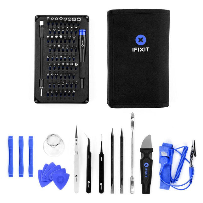
iFixit iFixit Pro Tech Toolkit
The Pro Tech Toolkit is the one thing every DIYer, fixer, hacker, hobbyist, and professional needs to tackle any job. Every tool in the Pro Tech Toolkit has been re-engineered to be better. From the 64 Bit Driver Kit to the iFixit Opening Picks, every tool is specially designed and selected to maximize your repair capabilities. At the core of this kit is the iFixit 64 Bit Driver Kit, designed with extensive research into what fastener types are currently used in the consumer electronics industry and which legacy fasteners are still in demand by consumers. From the Apple Watch with its new tiny Tri-Point screws to vintage Nintendo game consoles with gamebit fasteners, the 64 bit kit covers them all with the highest quality CNC machined bits. Even the sturdy case was carefully engineered, having no hinges or latches to break, and features a sorting tray inside the magnetically attached lid. High-Performance Toolkit for DIY Repairs The perfect toolkit for pros to average joes. Contains all the poking, prying, gripping, lifting, ESD safety, and screw driving tools needed to service consumer electronics. Completely re-engineered to provide all the tools that you need, and none that you don't. Included Anti-Static Wrist Strap – protection for circuits against static electricity Small Suction Handle – suction handle for holding onto things lacking handles 3x iFixit Opening Tool – soft plastic prying tools 6x iFixit Opening Picks – thin prying tool for opening electronic devices Nylon Tipped Reverse Tweezers – to elevate and hold your work Angled ESD Tweezers – ESD-safe, feature teeth for tougher grip Blunt ESD Tweezers – ESD-safe, feature teeth for tougher grip Standard Spudger – tough antistatic tool for a variety of purposes Halberd Spudger – features a hook for scooping, scraping, pulling, and guiding.ESD-safe. Metal Spudger – for more powerful prying, scraping, probing, and poking action Jimmy – handy tool for 'Jimmy'ing open electronics. Magnetic Pad – Holds tiny screws and parts during repairs Tool Roll – Durable and compact Mako Precision Bit Set – all the bits needed for repairs on small electronics Mako Precision Bit Set Includes 64 Bit Driver 150 mm Flex Extension 4 mm Screwdriver Bits Phillips – 000, 00, 0, 1, 2 Flathead – 1, 1.5, 2, 2.5, 3, 4 mm Torx – T2, T3, T4, T5 Torx Security – TR6, TR7, TR8, TR9, TR10, TR15, TR20, TR25 Pentalobe – P2, P5, P6 JIS – J000, J00, J0, J1 Hex – 0.7, 0.9, 1.3, 1.5, 2, 2.5, 3, 3.5, 4, 4.5, 5 mm Tri-point – Y000, Y00, Y0, Y1 Nut Driver – 2.5, 3, 3.5, 4, 4.5, 5, 5.5 mm Square – 1, 2 Gamebit – 3.8, 4.5 mm Spanner – 6, 8 Triangle – 2, 3 mm Standoff Bit for iPhone Oval Bit Magnetic Pickup Bit SIM Eject Bit 1/4" to 4 mm Driver Adapter
€ 69,95
-

Sensepeek Sensepeek 6012 PCBite Kit incl. 2x SQ10 Probe for DMM
The SQ series of handsfree PCBite probes from Sensepeek are insulated, come with included color-coded cable holders and have a lower point of gravity making them even more stable compared with the original SP series of probes. All the loved features of handsfree measurement, exchangeable fine pitch spring tipped test needle and the minimalistic design is maintained to make traditional sized and handheld probes obsolete. Features All handsfree probes from Sensepeek makes instant measurements or long triggering sessions a breeze. No more soldering wires to connect your probe or complicated tools to setup, just positioning the probe needle on any test point or component in the signal path and release. Saves time and frustration during development, verification and repairs. The minimalist design and the spring-loaded test needle makes it possible to simultaneously measure on fine pitch components and nearby signals. Both length and weight of the SQ probes are perfectly balanced to be used with PCBite PCB holders and base plate which is a must for handsfree function. The probe holder comes with a powerful magnet in the base, as for all PCBite probes and holders which makes the probe easy to place and reposition. The SQ series of probes can be used handheld without the probe holder as they have an insulated grip but their full potential is used when measuring handsfree. Included 4x PCBite PCB holders 2x SQ10 probes and pin tipped test needles (red/black) 2x Banana to dupont test wires (red/black) 1x Large Base plate (A4) 1x Insulation cover for the base plate (A4) 1x Set of yellow insulation washers for the PCB holders 1x Set of cable holders (red/black) 2x Extra test needles 1x Micro fiber cloth Downloads User Guide (PCBite Kit) User Guide (SQ10)
€ 127,05
-
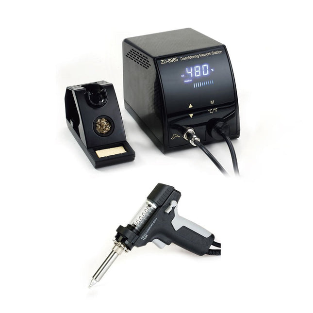
Zhongdi ZD-8965 Desoldering Station
The ZD-8965 is a digital temperature-controlled desoldering station equipped with ground protection and an LCD screen for temperature display. Despite its compact and robust design, this high-power desoldering station is easy to operate with just one hand. The ZD-8965 features a soldering gun with an integrated filter that captures any extracted material, allowing for continuous operation by simply replacing the filters. Additionally, a temperature sensor is embedded in the tip, enabling rapid response to temperature fluctuations for consistent performance. Features Effortlessly adjust the temperature between 160°C and 480°C using the convenient up/down buttons on the front panel. LED display to indicate the temperature in °C/°F Features an ergonomic pistol grip with a trigger for quick and efficient solder waste removal. The upgraded soldering gun includes a rear trigger, making it exceptionally convenient for replacing and cleaning components. Comes with a high-quality soldering gun and a sturdy holder. Equipped with a heavy-duty heater that ensures optimal desoldering performance every time. Specifications Station Voltage supply 220-240 V Power 140 W Vakuum pressure 600 mm HG Desoldering Gun Power 140 W (18 V DC)Heat up rating: 140 W Temperature 160-480°C (320-896°F) Heating element Ceramic heater Included 1x ZD-8965 Desoldering station 2x Spare soldering tips 3x Cleaning needles for desoldering tips 3x Spare filter for desoldering gun 1x Spare filter for desoldering station 1x Manual
€ 99,00
-

Red Pitaya Red Pitaya STEMlab 125-14 PRO Gen 2 Starter Kit (incl. Book)
This bundle includes the Red Pitaya STEMlab 125-14 PRO Gen 2 Starter Kit and the new book "Experimenting with Red Pitaya STEMlab Gen 2". The Red Pitaya STEMlab 125-14 PRO Gen 2 Starter Kit is a powerful and flexible platform for signal processing, data acquisition, and electronic measurement applications. Designed for engineers, developers, researchers, and educators, this kit provides everything required to start building advanced measurement and control systems. At the core of the kit is the STEMlab 125-14 PRO Gen 2 board, an upgraded and ultra-lightweight development platform. Powered by the Xilinx Zynq-7010 SoC with 512 MB of RAM, it combines FPGA programmability with ARM processing power to enable high-performance instrumentation and custom signal-processing solutions. The board offers 14-bit ADC and DAC resolution, a 125 MS/s sampling rate, an input range of ±20 V, and up to 60 MHz bandwidth. Its improved low-noise analog front-end, USB-C connectivity, and compact design make it suitable for demanding applications such as RF development, radar systems, photonics research, software-defined radio (SDR), and industrial automation. The Starter Kit includes all essential accessories for immediate use: a microSD card with preinstalled operating system, power supply, Ethernet cable for remote access, two 100 MHz oscilloscope probes, and SMA-to-BNC adapters for flexible signal connections. The Red Pitaya STEMlab 125-14 PRO Gen 2 Starter Kit is an excellent platform for rapid prototyping, FPGA development, measurement instrumentation, and advanced electronics experimentation. Features 14-bit ADC and DAC resolution 125 MS/s sampling rate ±20 V input range Up to 60 MHz bandwidth Xilinx Zynq-7010 SoC (FPGA + ARM processor) 512 MB RAM Low-noise analog front- and back-ends Applications RF development and testing Radar and wireless systems Software-defined radio (SDR) Photonics and optical research Industrial automation and control systems Signal analysis and instrumentation Rapid prototyping of electronic measurement systems Specifications Processor Dual-core ARM Cortex-A9 FPGA AMD Xilinx Zynq-7010 SoC RAM 512 MB (4 Gb) Storage microSD card (up to 32 GB) Operating System Linux-based Red Pitaya OS ADC Resolution 14-bit DAC Resolution 14-bit Bandwidth 60 MHz (DC) Sampling Rate 125 MS/s Analog Input Channels 2 Analog Output Channels 2 Input Voltage Range ±1 V (LV) / ±20 V (HV) Input Impedance 1 MΩ / 10 pF Output Voltage Range ±1 V Ethernet 1x Gigabit Ethernet (RJ45) USB 2x USB-C 2.0 (for power and console) Digital I/O 16x GPIO (3.3 V) Communication Interfaces I²C, SPI, UART, CAN Power Supply 5 V/3 A via USB-C Dimensions 106.8 x 60.0 x 17.9 mm Included 1x Red Pitaya STEMlab 125-14 PRO Gen 2 board 2x 100 MHz oscilloscope probes 2x SMA-to-BNC adapters 1x microSD card with preinstalled OS 1x USB-C Power supply 1x Ethernet cable Downloads Documentation Schematics Book: Experimenting with Red Pitaya STEMlab Gen 2 With this new book, Red Pitaya goes beyond a versatile board. It becomes a powerful laboratory instrument for precision measurement, analysis, and control. From the fundamentals of electronic project development, monitoring, control, and design to testing, this book walks you step-by-step through everything you need to know to harness the full potential of Red Pitaya hardware and software. The book presents real-time, FPGA-based projects that are developed on a PC using the Vivado environment, then transferred to the Red Pitaya for execution and testing. You will learn about enhanced performance, expanded I/O capabilities, improved FPGA features, and advanced connectivity options that open up new frontiers for precision measurement, monitoring, and control in your embedded applications. Inside the book you will discover: A deep dive into Red Pitaya architecture and hardware design Electronic experiments using Red Pitaya for measurement and monitoring Hands-on projects using the Python programming language Practical guidance for FPGA programming using Red Pitaya Red Pitaya FPGA projects using the Verilog HDL under Vivado IDE Practical design of electronic projects including measurement and testing Step-by-step examples that bridge theory and real-world implementation Whether you are designing your own electronic circuits, developing signal analysis tools, or creating real-time control or monitoring systems, this book provides you the knowledge and confidence you need to fully learn and customize the Red Pitaya platform.
€ 799,00
Best Price
-
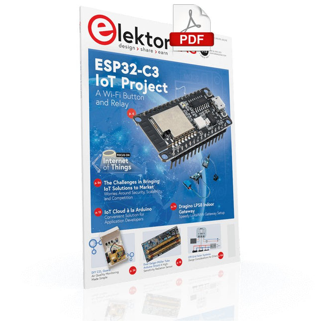
Elektor Digital Elektor May/June 2022 (PDF)
Your First Steps with an ESP32-C3 and the IoTA Wi-Fi Button and Relay IoT Cloud a la Arduino Dual Geiger-Müller Tube Arduino ShieldA High Sensitivity, Very Low-Power Radiation Sensor CO2 GuardA DIY Approach to Monitoring Air Quality MonkMakes Air Quality Kit for Raspberry PiMeasures Temperature and eCO2 Starting Out in ElectronicsWelcome to the Diode Tips & Tricks for Testing ComponentsNo Expensive Equipment Required Reducing the Power Consumption of Your Mole RepellerAn ATtiny13 Replaces a 555 Light Switch DeLuxA Solution for High-Precision Light-Controlled Switching The Challenges in Bringing IoT Solutions to MarketWorries Around Security, Scalability, and Competition Infographics 5-6/2022 Preferably Wired After AllTips for Developing a 1 Gbit/s Interface in an Industrial Environment Bringing Real-Time Object Detection to MCUs with Edge Impulse FOMO Traveling-Wave TubesPeculiar Parts, the Series Narrowband Internet of ThingsStandards, Coverage, Agreements, and Modules Dragino LPS8 Indoor GatewaySpeedy LoRaWAN Gateway Setup Explore ATtiny Microcontrollers Using C and Assembly LanguageSample Chapter: ATtiny I/O Ports Err-lectronicsCorrections, Updates and Readers’ Letters LoRa GPS Tracker UpdateReceive and Show Location Using a Raspberry Pi Circuit Simulation with TINA Design Suite & TINACloudSample Chapter: Sinusoidal Oscillators From Life’s ExperienceAssembly Line Work The WinUI Graphics Framework for Windows AppsA Small Demo Application GUIs with PythonWorst GUI of the world Off-Grid Solar SystemsElectrical Energy Independent of the Mains Grid The 10-Year SmartphoneRenew Your Expectations HexadokuThe Original Elektorized Sudoku
€ 7,50
-

Elektor Digital Elektor Special: Sensoren für Wetter und Umwelt (PDF)
Bauen Sie Ihre perfekte Wetterstation oder forschen Sie zusammen mit der ganzen Welt an Umweltdaten. Mit vielen praktischen Projekten für Arduino, Raspberry Pi, NodeMCU, ESP32 und weiteren Developmentboards. Wetterstationen erfreuen sich seit Jahrzehnten großer Beliebtheit. Ob in aktuellen oder längst eingestellten Elektronik-Magazinen – regelmäßig finden sich Beiträge zum Eigenbau einer Wetterstation. Im Laufe der Jahre wurden diese Systeme immer ausgefeilter und können heute nahtlos in das Smart Home integriert werden. Allerdings erfordert dies oft die Bindung an einen (teuren) Markenhersteller, der sämtliche Komponenten abdeckt. Mit Ihrer eigenen Wetterstation können Sie jedoch mühelos mithalten – und sogar Messwerte erfassen, die kommerzielle Geräte nicht bieten. Dabei kommt der Spaß nicht zu kurz: Sie erweitern spielerisch Ihr Wissen über Elektronik, moderne Mikrocontroller-Developmentboards und Programmiersprachen. Schon für weniger als zehn Euro können Sie erste Umweltdaten erfassen und Ihr System Schritt für Schritt mit wachsendem Interesse weiter ausbauen. Aus dem Inhalt: Wind und Wetter auf der Spur Wetterdisplay mit OpenWeatherMap und Vakuum-Fluoreszenzanzeige Flüchtige organische Verbindungen in der Atemluft Mit MQ-Sensoren arbeiten: Kohlenmonoxid messen – geruchlos aber extrem giftig CO2-Ampel mit ThingSpeak-IoT-Anbindung Ein Gießautomat für Ihre Pflanzen Gutes Raumklima: Temperatur und Luftfeuchtigkeit sind wichtige Kriterien Schickes Thermometer mit alter Röhrentechnik Nostalgisches Wetterhäuschen für die ganze Familie Luftdruck und Temperatur genau messen Sonnenbrand-Warngerät DIY-Sensor für die Sonnenscheindauer Das Smartphone zeigt’s an: Nebel oder klare Sicht? Erdbeben erkennen Pegelstände von Gewässern und Behältern pH-Wert von Gewässern bestimmen Radioaktive Strahlung erkennen Mit GPS wissen Sie weltweit, wo ihr Sensor ist Logdateien mit Zeitstempel auf SD-Karten speichern LoRaWAN, The Things Network und ThingSpeak LoRaWAN-Gateway für TTN betreiben Mega-Display mit Wettervorhersage
€ 11,90
Members: € 10,71
-

Elektor Publishing Introduction to Electronic Filters
Learn RC and RL Filters with Hands-On Circuits and Simulation Introduction to Electronic Filters is your comprehensive guide to understanding, designing, and applying first-order electronic filters using resistors, capacitors, and inductors. Whether you are a student, maker, or educator, this book demystifies the theory behind RC and RL filters and bridges the gap between concepts and real-world applications through simulation and experimentation. From the basics of frequency response and phase shift to hands-on breadboard builds and Python-based simulations, this book offers a deeply practical learning experience. You will learn to analyse filters using Bode plots and phasors, and explore applications in audio tone shaping, sensor signal conditioning, noise reduction, and power supply filtering. As you progress, you’ll build, measure, simulate, and tune filters using modern tools like CircuitLab, Python, and the Analog Discovery 3. Each chapter includes thoughtfully crafted activities that reinforce learning by doing – designing filters for specific tasks, simulating dynamic behaviour, and observing how theory translates into performance. Inside you’ll find: A clear introduction to the fundamentals of electronic filters Detailed explanations of RC and RL filters, cutoff frequency, and phase Guided activities using both simulation and hardware tools Real-life applications in audio, sensors, power supplies, and more A beginner-friendly primer on Python and algebra for electronics Whether you’re working through simulations or experimenting with real components on your workbench, this book will help you develop a solid understanding of electronic filters and their role in practical circuits.
€ 39,95
Members: € 35,96
-
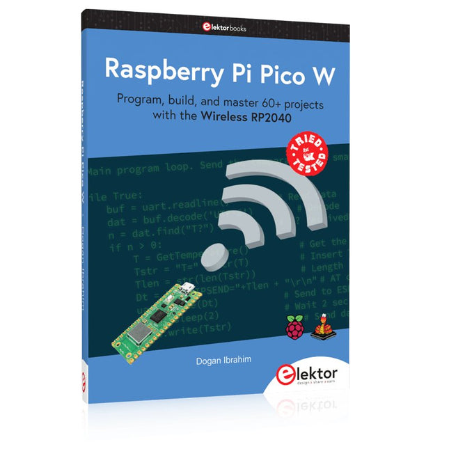
Elektor Publishing Raspberry Pi Pico W (Book)
Program, build, and master 60+ projects with the Wireless RP2040 The Raspberry Pi Pico and Pico W are based on the fast, efficient, and low-cost dual-core ARM Cortex M0+ RP2040 microcontroller chip running at up to 133 MHz and sporting 264 KB of SRAM and 2 MB of Flash memory. Besides spacious memory, the Pico and Pico W offer many GPIO pins, and popular peripheral interface modules like ADC, SPI, I²C, UART, PWM, timing modules, a hardware debug interface, and an internal temperature sensor. The Raspberry Pi Pico W additionally includes an on-board Infineon CYW43439 Bluetooth and Wi-Fi chipset. At the time of writing this book, the Bluetooth firmware was not yet available. Wi-Fi is however fully supported at 2.4 GHz using the 802.11b/g/n protocols. This book is an introduction to using the Raspberry Pi Pico W in conjunction with the MicroPython programming language. The Thonny development environment (IDE) is used in all of the 60+ working and tested projects covering the following topics: Installing the MicroPython on Raspberry Pi Pico using a Raspberry Pi or a PC Timer interrupts and external interrupts Analogue-to-digital converter (ADC) projects Using the internal temperature sensor and external sensor chips Using the internal temperature sensor and external temperature sensor chips Datalogging projects PWM, UART, I²C, and SPI projects Using Bluetooth, WiFi, and apps to communicate with smartphones Digital-to-analogue converter (DAC) projects All projects are tried & tested. They can be implemented on both the Raspberry Pi Pico and Raspberry Pi Pico W, although the Wi-Fi-based subjects will run on the Pico W only. Basic programming and electronics experience are required to follow the projects. Brief descriptions, block diagrams, detailed circuit diagrams, and full MicroPython program listings are given for all projects.
€ 44,95
Best Price
-

Weller Weller WT1013 Digital Soldering Station (95 W)
The Weller WT 1013 soldering station set includes the WT 1 supply unit, the WP 80 soldering iron and the WSR 201 safety rest. It is stackable and thus creates more space in the workplace. With an integrated usage sensor, the soldering tool switches off automatically. Specifications Channels 1 Voltage 230 V Power 95 W Display Backlit LCD Temperature range 50 °C - 450 °C Temperature stability ±2 °C Temperature accuracy ±9 °C Fuse 0.5 A Equipotential bonding on WT compatible on ESD-safe on Power cable EMEA Dimensions 149 x 138 x 101 mm Weight (approx.) 1.9 kg
€ 441,65


