
Search results for "elektor or ultimate or sensor or kit"
-

Elektor Digital Raspberry Pi ontdekken in 45 Elektronica projecten (2e versie) | E-book
Met de Raspberry Pi heeft u voor slechts een paar tientjes een complete computer in handen, waar op eenvoudige wijze allerlei elektronica aangesloten kan worden. In deze 2e herziene en uitgebreide versie gaan we in op een van de sterke kanten van de Raspberry Pi: de combinatie van programmeren en elektronica. Na een korte introductie van de Raspberry Pi wordt de benodigde software geïnstalleerd. Op de SD-kaart die u bij dit boek kunt aanschaffen, is die allemaal al aanwezig voor de Raspberry Pi. Aan de (optionele) Windows PC kant gebeurt dit met gratis software die u kunt downloaden. Daarna volgt een beknopte inleiding in het besturingssysteem Linux en gaan we programmeren in Bash, Python en JavaScript. De nadruk ligt hierbij op Python, maar in alle gevallen houden we het kort. We bespreken net voldoende zodat u de projecten kunt begrijpen en aan uw wensen aanpassen, en gaan dan aan de slag met leuke projecten. Maar liefst 45 spannende en interessante projecten worden in detail besproken en uitgelegd. Van wisselknipperlicht, aansluiten van een elektromotor, het verwerken en maken van analoge signalen tot lichtmeter en temperatuurregeling. Maar ook gecompliceerdere projecten zoals een motorsnelheidsregeling, webserver met CGI, client-server applicaties en Xwindows programma‘s. U kunt dit boek gebruiken als projecten boek en de projecten nabouwen en in de praktijk inzetten. Door de duidelijke uitleg, schema‘s en foto‘s van de opstellingen op een steekbord wordt het nabouwen een erg leuke bezigheid. RPi Alle software voor de RPi is voorgeïnstalleerd op een SD-kaart die u bij dit boek kunt aanschaffen. Dat wil zeggen dat alle software en drivers voor SSH, SPI, I²C, GPIO, PWM, muziek, Python Ontwikkelversie, wxPython, IdleX en de seriële verbinding gegarandeerd werken. Tevens staan alle broncodes van de projecten uitdit boek op deze kaart. Windows-PC In het gratis download-pakket dat bij dit boek hoort, vindt u de software die in dit boek gebruikt wordt op de Windows-PC handig bij elkaar in een enkel ZIP-bestand. Alle software is gratis. Tevens bevat het pakket een filmpje van de Nutteloze Doos (Useless Machine) van project 13.4. Software download-pakket WinOscillo Putty Xming WinSCP DiskImager Notepad2 IdleX Useless Box film
€ 29,95
Members: € 26,96
-

Elektor Digital Practical Electronics Crash Course (E-book)
Learning circuit design the fun way Welcome to the world of electronics! Getting started in electronics is not as difficult as you may think. Using this book, you will explore and learn the most important electrical and electronics engineering concepts in a fun way by doing various experiments and by simulating circuits. It will teach you electronics practically without getting into complex technical jargon and long calculations. As a result, you will be creating your own projects soon. No prior knowledge of electronics is required, only some basic algebra is used in a few simple calculations. Many tested and working projects and simulations are presented to familiarise yourself with the construction of electronic circuits. Circuit simulation is introduced at an early stage to enable you to experiment with circuits easily without breaking anything. You will learn: The concepts of voltage, current, and power AC and DC Basic lamp circuits with switches Passive components: resistors, capacitors & inductors RC & RCL circuits Electromagnetism Loudspeakers, relays, buzzers, and transformers Active components: diodes & LEDs, bipolar transistors & MOSFETs Transistor-based switching circuits Optocoupler circuits Astable & monostable multivibrators Using the 555 timer IC The operational amplifier Digital logic Advanced examples: amplifiers, oscillators, filters, and sensors Test and measurement tools Microcontrollers: Arduino UNO, ESP32, Raspberry Pi Pico, and Raspberry Pi Reading datasheets and best practices for selecting components EMC & EMI and norms & regulations
€ 32,95
Members: € 29,66
-
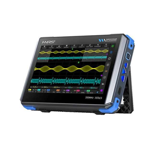
FNIRSI FNIRSI DPOS350P (4-in-1) 2-ch Tablet Oscilloscope (350 MHz) + Signal Generator + Frequency Response Analyzer + Spectrum Analyzer
2 Channels • 350 MHz • 1 GSa/s • 50,000 wfm/s • 7 inch Touchscreen The FNIRSI DPOS350P is a sleek 4-in-1 powerhouse in tablet form! This compact and portable device packs serious functionality: it combines a 2-channel oscilloscope (350 MHz), a signal generator (50 MHz), a frequency response analyzer (50 MHz), and a spectrum analyzer (200 kHz–350 MHz) – all in one unit. Whether you're in R&D, troubleshooting, or field testing, the DPOS350P delivers the tools you need to measure, generate, analyze, and visualize electronic signals with precision and clarity. Its responsive high-resolution touchscreen and intuitive controls make signal analysis fast, flexible and efficient. Features Powerful Multi-Function Integration 350 MHz 2-channel oscilloscope with 1 GSa/s real-time sampling 50 MHz signal generator with 14 standard + custom waveforms Spectrum analyzer (200 kHz–350 MHz): Perfect for EMI, RF & HF testing Frequency response analyzer (FRA) up to 50 MHz High-Performance Waveform Capture 50,000 wfm/s refresh rate for real-time signal clarity 350 MHz bandwidth (single-channel mode) Detects rare and low-probability anomalies Crisp Display & Smooth Operation 7" IPS touchscreen (1024 x 600 resolution) Switch between grayscale and color temperature display Easy to operate in various test environments Reliable, Protected & Fast-Charging High-voltage protection up to 400 V Fast charging with QC 18 W (full charge in 2 hours) Built for stable long-term operation Data Storage & Export Save up to 500 waveform records + 90 screenshots USB export for easy reporting and offline analysis Specifications General Display 7 inch (IPS full viewing angle) Resolution 1024 x 600 pixels Interaction mode Capacitive touch screen Total power consumption 10 W Power-on configuration 5 presets Charging QC 18 W, 12 V/1.5 A (USB-C) Battery 3.7 V, 8000 mAh lithium battery Battery life approx. 3 hours in operation, 5 hours standby Heat dissipation Air cooling Expansion interface USB data port Automatic shutdown 15~60 minutes / off Firmware upgrade Support .iso image upgrade Languages English / Portuguese / Russian / Chinese Dimensions 190 x 128 x 37 mm Oscilloscope Analog channels 2 Analog bandwidth 350 MHz Rise time 1ns Real-time sampling rate 1 GSa/s Memory depth 60 Kpts Input impedance 1 MΩ / 14PF Time base range 5ns ~ 50s Roll time base 50ms ~ 50s Vertical sensitivity 2 mV ~ 20 V (1X) Vertical range 16 mV ~ 160 V (1X) DC accuracy ±2% Time accuracy ±0.01% Input coupling DC / AC Probe attenuation 1X / 10X / 100X Hardware bandwidth limit 150M / 20M High resolution mode 8bit ~ 16bit Parameter measurements 12 types Cursor measurement Time, period, frequency, level, voltage Trigger detection Digital trigger Trigger channel CH1 / CH2 Trigger mode Auto / Single / Normal Trigger edge Rising edge / Falling edge Trigger suppression L1 ~ L3 Trigger level Manual / automatic 10% ~ 90% Screenshot storage 90 pictures Waveform storage 500 groups Background grid Display / hide Waveform movement Coarse adjustment / fine adjustment Overvoltage protection Withstand voltage 400 V Waveform brightness Adjustable Simple FFT display Yes Digital fluorescence Yes Color temperature display Yes X-Y mode Yes ZOOM time base Yes One-key automatic adjustment Yes One-key return to zero Yes Data browser Yes Signal Generator Waveform types 14 standard functions + captured waveform Frequency 0~50 MHz (sine wave only, other waveforms up to 10M/5M/3M) Amplitude 0~5 VPP Offset -2.5 V ~ +2.5V Duty cycle 0.1~99.9% Frequency resolution 1 Hz Amplitude resolution 1 mV Offset resolution 1 mV Duty cycle resolution 0.1% Customizable captured waveform 500 groups Frequency Response Analyzer (FRA) Excitation signal frequency 100 Hz ~ 50 MHz Excitation signal amplitude 0~5 VPP Excitation signal offset -2.5V ~ +2.5V Excitation frequency count 20~500 Cursor measurement Frequency / gain / phase Operating mode Single / cyclic System calibration Yes Spectrum Analyzer Conversion method FFT FFT length 4K ~ 32K Frequency range 200 KHz ~ 350 MHz Level range -60 dBmV ~ +260 dBmV Cursor measurement Frequency / amplitude Marking parameter Maximum energy harmonic Waterfall chart Yes 3D waterfall chart Yes Automatic adjustment Yes System calibration Yes Included 1x FNIRSI DPOS350P Oscilloscope (4-in-1) 2x 350 MHz Probes 1x QC 18 W Fast Charger (EU) 1x USB-C Cable 1x Alligator Clip 1x Storage Bag 1x Manual Downloads Manual Firmware
€ 309,00€ 259,00Best Price
-

Elektor Digital Digitale Logik selbst entwickeln (PDF)
Dieses Buch nimmt Sie mit auf eine Entdeckungsreise in die Welt der digitalen Elektronik. Nach dem Aufbau einer soliden Wissensbasis hierüber verlagert sich der Schwerpunkt zur programmierbaren Logik. Wie lassen sich mit vorhandenen Bausteinen logische Systeme aufbauen und wie koppelt man sie sicher und störungsfrei an die analoge Außenwelt? Das sind Fragen, die das Buch beantwortet. Moderne logische Systeme sind so komplex, dass deren Aufbau mit separaten Bauelementen wie einzelnen Gattern, Flipflops, Zählern oder Teilern eine fast unmögliche Aufgabe ist. Deshalb beschäftigt sich das Buch in der zweiten Hälfte mit der programmierbaren Logik in Form von FPGA- und CPLD-ICs. Sie lernen Methoden kennen, die als Brücke zwischen dem klassischen Design und der zeitgemäßen Entwicklung mit FPGA fungieren. Neben dem schematischen FPGA-Entwurf setzt sich das Buch auch mit Sprachen wie Verilog und VHDL auseinander. Das abschließende Projekt, eine Uhr mit Alarmfunktion in Verilog und VHDL, zeigt den praktischen Nutzen der programmierbaren Logik. Neben den erforderlichen Programmierkenntnissen ist auch der praktische Schaltungsaufbau von Bedeutung. Der Autor erläutert die wesentlichen Bedingungen hierfür, beispielsweise die der erforderlichen Stromversorgung und der optimalen (Analog-)Signalverarbeitung. Alle in diesem Buch besprochenen Beispiele lassen sich mit der kostenfreien FPGA-Entwicklungsumgebung Quartus von Altera realisieren.
€ 44,80
Members: € 40,32
-

Elektor Digital Introduction to Control Engineering (E-book)
This book is aimed at practising engineers, students and hobbyists. It is intended as a source of reference for hardware and software associated with instrumentation and control engineering. Examples are presented from a range of industries and applications. Throughout the book, circuit diagrams and software listings are described, typical of many measurement and control applications. The hardware and software designs may be used as a basis for application by the reader. The book contains examples of PIC, PLC, PAC and PC programming. All code samples are available to download free of charge from the support website. After an introductory section on control theory and modelling, the text focus is upon software for control system simulation and implementation, with appropriate reference to interfacing, electronic hardware and computing platforms. Introduction to Control Engineering is a sourcebook of solutions for control system applications!
€ 24,95
Members: € 22,46
-

Elektor Publishing Grundlagen und Schaltungen der Stromversorgungstechnik
Aus der Reihe "Stromversorgung ohne Stress" (Band 1) 2., überarbeitete und erweiterte Auflage Eines haben alle elektronischen Schaltungen und Geräte gemeinsam: Ihre Funktion hängt von der Stromversorgung ab. Deshalb muss dieser Baugruppe besondere Aufmerksamkeit gewidmet werden. Dieses Buch beinhaltet Grundlagen und Schaltungen der Stromversorgungstechnik für elektronische Geräte aus der Praxis. Dem aktuellen Trend folgend behandelt der Autor insbesondere die mobile Stromversorgungstechnik sowie die Schaltnetzteiltechnik. Dabei wird berücksichtigt, dass Stromkonstanter gegenüber Spannungskonstantern zunehmend an Bedeutung gewinnen. Im Buch finden sich die notwendigen Grundlagen zum Bau eigener Stromversorgungsgeräte und -baugruppen. Außerdem enthält es ganz praktische Anwendungsbeispiele, z. B. für den Ersatz defekter Netztransformatoren, für die mobile Stromversorgung auf Fahrradtouren oder für den Betrieb von LEDs. Diese zweite Auflage wurde gründlich überarbeitet, Fehler wurden behoben und einige Ergänzungen vorgenommen. Der Autor Franz Peter Zantis ist Energieanlagenelektroniker und Ingenieur der Nachrichtentechnik. In einem Forschungsprojekt hat er sich ausführlich mit der Stromversorgung eigensicherer Geräte auseinandergesetzt und zahlreiche Beiträge zum Thema Schaltnetzteile veröffentlicht.
€ 39,80
Best Price
-

Elektor Digital CAN und EOBD in der Fahrzeugtechnik (E-book)
CAN und EOBD in der Fahrzeugtechnik (E-book)
€ 34,80
Members: € 31,32
-

Elektor Digital Programmierbare Taschenrechner selbst gebaut (E-book)
Programmierbare Taschenrechner selbst gebaut (E-book)
€ 29,80
Members: € 26,82
-

Elektor Digital I/O-Projekte für den PC (E-book)
I/O-Projekte für den PC (E-book)
€ 34,80
Members: € 31,32
-

Elektor Publishing 8-Bit-Mikrocontroller
PIC und AVR verstehen In diesem Buch werden wir uns ausschließlich mit 8-Bit-Mikrocontrollern beschäftigen, und zwar mit Mikrocontrollern der 8-Bit-PIC- und der 8-Bit-AVR-Mikrocontroller-Linien. Bei der PIC-Familie handelt es sich dabei um PIC10, PIC12, PIC16 und PIC18; bei der AVR-Familie um ATtiny, ATmega und ATxmega. Die vorgestellten 8-Bit-Chips sind für sehr viele Anwendungen vollkommen ausreichend und preislich auch attraktiv. Durch die Lektüre des Buches erhalten Sie ein fundiertes Wissen über die genannten 8-Bit-Mikrocontroller, über ihre Architektur, ihre Pinbelegungen und über ihre Programmierung. Weil wir uns in diesem Buch mit den Grundlagen der Architektur der PICs und AVRs vertraut machen möchten, werden wir auch für alle PIC- und AVR-Anwendungen Assembler einsetzen, denn die Assembler-Sprache erlaubt es, die Technik im Detail kennenzulernen. Wenn man wirklich wissen möchte, was sich im Mikrocontroller abspielt, greift man zu Assembler. Damit hat man die beste Gelegenheit, sehr nah an den Kern zu kommen. Und wenn man schon einen Mikrocontroller-Typ kennengelernt und verstanden hat, ist es bei dem nächsten deutlich einfacher, auch wenn er von einem anderen Hersteller kommt. Bei anderen Programmiersprachen bleibt die Technik immer ziemlich tief versteckt. Die Assembler-Beispiele sind so einfach gestaltet, dass sie jeder mit den im Buch aufgezeigten Programmiertechniken erstellen kann. Weil es sich um einfache Beispiele handelt, werden wir sie alle auf einer universellen Lochrasterplatine realisieren. Manche sind auch auf einem Experimentier-Breadboard umsetzbar.
€ 39,80
Best Price
-

Elektor Digital LEDs 5 (PDF)
Inhalt Praxis LED-KommunikatorDesign-Studie: Verwendung von handelsüblichen LEDs zur bidirektionalen Kommunikation Nachrichten-Ticker Bau eines Internet-News-Tickers ALS es Licht wurde Controller steuert Beleuchtungseinrichtungen nach Umgebungshelligkeit und Uhrzeit BULI - Button-Lichtspiele Effekte mit LED2812 und Cortex-M0+ Theorie & Anwendung DesignCorner: Schaltungen, Tipps und Kniffe- Posistor gegen den Hitzetod- High-Brightness-LEDs an Niedervolt-Stromversorgungen betreiben- Derating mit PTC-Thermistoren in LED-Treiberschaltungen- Der Umgang mit LED-Strings- LED-Treiber für unterschiedliche Wandler-Topologien- LED-Konstantstromtreiber in Schaltreglertechnik Grenzen überschreiten Ansteuerung von LEDs mit gepulstem Überstrom Ansteuerung von LED-Matrixschaltungen MultitalentController treibt LEDs, regelt Solarzellen und lädt Batterien Dimmungstechniken für LEDs Info OLED – Die FlächenlichtquelleZum Entwicklungsstand der organischen Leuchtdiode 400 LED-Lampen auf dem Prüfstand Über dem LimitLEDs mit höheren Treiberströmen ansteuern AktuellNeue LEDs, LED-Lampen, Treiber, Netzteile, Zubehör und Entwicklungs-Tools
€ 17,50
Members: € 15,75
-
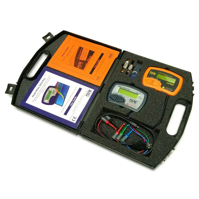
Peak Peak Atlas Pro Pack (LCR45 & DCA75)
This pack contains the LCR45 Passive Component Impedance Meter, great for advanced hobbyists and professionals. It also contains the very popular DCA Pro (model DCA75), fantastic for component identification, pinout identification, detailed characteristic measurement and curve tracing on a PC. Complete with USB cable and software on a USB flash drive. DCA75 Building on the continued success of Peak's existing component identification and analysis instruments, the DCA Pro brings an array of exciting new features for the hobbyist and professional alike. The DCA Pro is an advanced new design that features a graphics display, USB communications, PC Software and an enhanced component identification library. Automatic component type identification Automatic pinout identification (connect any way round) The DCA Pro supports all the components that the popular Peak Atlas DCA55 supports, but adds plenty more. Components supported include: Transistors (including Darlingtons), Silicon and Germanium types. Measures gain, Vbe and leakage MOSFETs, enhancement mode and depletion mode types. Measure on-threshold (at 5 mA) and approx transconductance (for span of 3-5 mA) JFETs, including normally off SiC types. Measures pinch-off voltage (at 1 uA) and approx transconductance (for span of 3-5 mA) IGBTs (insulated gate bipolar transistors). Measures on-threshold (at 5 mA) Diodes and Diode networks LEDs and bicolour LEDs (2 lead and 3 lead types) Zener Diodes with measurement of zener voltage up to 9 V at 5 mA Voltage regulators (measures regulation voltage, drop-out voltage, quiescent current) Triacs and Thyristors that require less than 10 mA of gate current and holding current Stand-alone or with a PC The instrument can be used stand-alone or connected to a PC. Either way, the DCA Pro will automatically identify the component type, identify the pinout and also measure a range of component parameters such as transistor gain, leakage, MOSFET and IGBT threshold voltages, pn characteristics and much more. Curve Tracing When connected to a PC using the supplied USB cable, a range of low current curve-tracing functions can be performed. Various graph types are available, with more to follow: Bipolar transistor output characteristics, IC vs VCE Bipolar transistor gain characteristics, HFE vs VCE Bipolar transistor gain characteristics, HFE vs IC MOSFET and IGBT output function, ID vs VDS MOSFET and IGBT transfer function, ID vs VGS JFET output function, ID vs VDS JFET transfer function, ID vs VGS Voltage regulator, VOUT vs VIN Voltage regulator, IQ vs VIN. PN junction I/V curves, forward and reverse options (for Zener diodes) Curve tracing is performed using test parameters in the range of +/-12 V or +/-12 mA. All curve-tracing data can be instantly pasted into Excel for further graphing and analysis. PC Software is included with the DCA Pro on a Peak USB memory stick. Software designed for Windows 7 and higher (all 32 or 64 bit). LCR45 A great handheld LCR analyzer that can measure the value of your passive component (inductor, capacitor or resistor) and also measure the detailed impedance in a number of modes. The LCR45 offers enhanced measurement resolution (better than 0.1 uH!) whilst also giving you continuous fluid measurements. Additionally, the test frequencies of DC, 1 kHz, 15 kHz and 200 kHz can be set to automatic or manual modes. Supplied with removable gold plated hook probes, battery and user guide. Compatible with standard 2 mm test connectors. Not designed for in-circuit use. Automatic or manual component type selection: Inductor, Capacitor or Resistor Automatic or manual test frequency selection: DC, 1 kHz, 15 kHz and 200 kHz Inductance from 0.1 uH to 10 H Capacitance from 0.1 pF to 10,000 uF Resistance from 0.1 Ohm to 2 MOhm Inductance measurement also shows DC winding resistance Display of "Component type and values", "Complex Impedance", "Magnitude/Phase" and "Admittance" Test frequency displayed for all measurements Typical accuracy of 1.5% for inductors and capacitors (see spec table for details) Typical accuracy of 1% for resistors Test lead complete with gold plated 2 mm plugs and sockets Supplied with removable gold plated hook probes Included LCR45 DCA75 Extra GP23 Battery Extra AAA cell Dual Carry Case
€ 325,49


