"Wie kann ich die klanglichen Eigenschaften meiner Lautsprecherboxen optimieren? Wie sind sie im Raum aufzustellen, damit die Wiedergabe akustisch voll zur Geltung kommt?" Das sind Fragen, die Sie sich sicherlich auch schon gestellt haben, ohne eine befriedigende Antwort zu erhalten.
Das Buch räumt mit allen Ungereimtheiten auf, die durch widersprüchliche Aussagen von Handel und Werbung entstehen. Es beginnt mit den Problemen der (Raum)Akustik wie Aufstellung der Boxen, Frequenzgang, Baßwiedergabe und Richtcharakteristik. Es folgt der Aufbau und die Wirkungsweise von Lautsprecherchassis. Das ist nicht nur eine Auflistung bestehender Systeme, sondern auch eine klare Gegenüberstellung deren Vor- und Nachteile.
Nicht zu kurz kommt die Theorie dynamischer Lautsprecher. Dazu gehören: Übertragungsfunktion, Impedanz, Filter, Hoch-, Band- und Tiefpaß, Frequenzweichen usw. Es folgen Überlegungen zu Baßreflex- und geschlossenen Lautsprecherboxen. Außerdem bietet Ihnen das Buch die Möglichkeit, Lautsprecherboxen sowie die mechanischen Parameter einzelner Chassis elektronisch zu beeinflussen. Schließlich gibt es noch Hinweise und Tips für Messungen an Chassis und Boxen.
Ob Sie nun industriell gefertigte Boxen oder selbstgebaute aufstellen wollen: Mit dem Buch können Sie Ihre Boxen an Ihren Verstärker in Ihrem Hörraum optimal anpassen.
This kit includes iFixit's widest assortment of bits, complete with every driver head you’ll need to tackle any repair or DIY project. It includes standard bits like Phillips and Flathead in a full range of sizes to handle everything from precision electronics repair to home DIY projects. And it wouldn’t be an iFixit bit set if it didn’t include all the exotic bits from Pentalobes for Apple iPhone and MacBook repair to Gamebits for your vintage Nintendo consoles.
All of the next-gen bit sets have been re-designed in order to maximize convenience and usability. The bit set lid is held in place with magnets to increase product lifespan (no more broken hinges or clasps) and also mounts to the back of the bit set case to keep it out of the way while you do your work. If you need help keeping your screws and parts organized, you can use the lid’s integrated sorting tray. The 4 mm bits have been adjusted and have now a longer neck for a deeper and more precise reach.
Toolkit Includes
Easy-to-Open Magnetized Case
Lid with Built-in Sorting Tray
4 mm Aluminum Bit Driver
1/4' Aluminum Bit Driver
4 mm Screwdriver Bits
Phillips - 000, 00, 0
Flathead - 1, 1.5, 2, 2.5, 3, 3.5 mm
Torx - T2, T3, T4, T5
Torx Security - TR6, TR7, TR8
Pentalobe - P2, P5, P6
JIS - 000, 00, 0, 1
Hex - 0.7, 0.9, 1.3, 1.5 mm
Hex Security - 2, 2.5, 3, 3.5 mm
Tri-point - Y000, Y00, Y0, Y1
Nut driver - 2.5, 3, 3.5, 4, 4.5, 5, 5.5 mm
Gamebit - 3.8, 4.5 mm
Spanner - 4, 6
Triangle - 2, 2.2, 2.6, 3 mm
Oval Bit
iPhone Standoff Bit
Sim Eject Bit
Magnetic Pickup Bit
1/4' Screwdriver Bits
Phillips - 1, 2, 3
Flathead - 4, 5, 6, 7, 8 mm
Hex Security - 4, 5, 6, 7, 8 mm
Hex Security SAE - 1/8, 9/64, 5/32, 3/16, 7/32, 1/4
Pozidriv - PZ0, PZ1, PZ2, PZ3
Torq-set - 6, 8, 10
Spanner - 8, 10, 12
Square - 0, 1, 2, 3
Spline - M5, M6, M8
Torx Security - TR9, TR10, TR15, TR20, TR25, TR27, TR30, TR35, TR40
Tri-wing 1, 2, 3, 4
Clutch 1, 2, 3
Schrader Valve
Hook Drive
1/4' to 4 mm Adapter
1/4' Driver to 1/4' Socket
1/4' Driver to 3/8' Socket
1/4' Socket to 1/4' Driver
Specifications
Bit Metal: 6150 Steel
Driver Material: Anodized Aluminum
Case Material: ABS
Foam: EVA
Lancé en mars 2012, plus les 30 millions d'exemples nanométriques du Raspberry Pi exposés. Il s’agit d’une contribution à la révolution des technologies de l’information et d’un grand stimulant pour le développement du monde de l’électronique. Le succès de la « tarte à la framboise » (traduction littérale de Raspberry Pie) est le résultat de l'industrie micro-électronique de transformation des produits.
Eben Upton, son créateur, âme à l'origine, les acheteurs étaient presque tous des makers , adultes en général. Cependant la plupart d'entre eux étaient également des ingénieurs professionnels. Rapidité, les gens sont responsables de leurs activités personnelles lors de l'utilisation du Raspberry Pi avec une plateforme informatique stable, et ils sont également adoptés pour leur métier.
La Fondation Raspberry Pi édite un magazine édité par la communauté Raspberry Pi : le MagPi (en anglais). Le magazine aborde les passions selon la nature du numérique nano-ordonné et global. Il contient des bancs d'essai de nouveaux produits, de nombreux tutoriels et un grand nombre de projets. Les membres de la communauté Raspberry Pi participent à leur expérience.
La maison d'édition Elektor s'associe à la Fondation Raspberry Pi pour la publication dans le magazine français MagPi. Il est conçu pour assembler 84 projets publics du MagPi en développant l'utilisation du Raspberry Pi et son inspiration.
Grâce à la taille fine et aux possibilités du Raspberry Pi, les créateurs du monde sont fiers des idées des plus folles.
Partez en voyage dans un monde où est faisable !
Le Raspberry Pi à toutes les sauces pour ?
s'inspirateur des projets réalisés par les membres de la communauté
dénicher des utilisations inouïes
découvrir des accessoires et technologies diverses
entrer dans une communauté intégrée et active de Raspberry Pi
Schon jeder hat erlebt, dass bei medizinischen Untersuchungen nicht ausreichend erklärt wird, was durch und mit den eingesetzten Geräte konkret vor sich geht. Dieses Buch kann hier unterstützend eingreifen und beschreibt auf verständliche Weise, wie die Medizintechnik funktioniert. Sowohl diejenigen, die nur eine oberflächliche Erklärung suchen als auch der Personenkreis, der etwas tiefer ins Details gehen will, finden in diesem Buch eine Antwort auf viele Fragen.
Zunächst werden die biologischen Grundlagen soweit erklärt, wie sie für das weitere Verständnis nötig sind. Danach wird auf die biologische Messtechnik und die Messaufnehmer sowie auf die elektronische Verarbeitung eingegangen. Gerüstet mit diesem Wissen folgt dann die Beschreibung verschiedener Anwendungen (z. B. EKG, EEG, EMG, Biofeedback) anhand einfacher Schaltungen. Weitere Anwendungen, wie beispielsweise die Kernspintomografie und Bestrahlungen, runden das Buch ab.
Wer sich dieser Thematik auf eine eher spielerische Art und Weise annähern möchte, findet hier ein eigenes Kapitel, in dem faszinierende parapsychologische Effekte anhand von telekinetischen Anwendungen vorgestellt werden, wie z. B. eine gedankenmanipulierte Eisenbahnsteuerung.
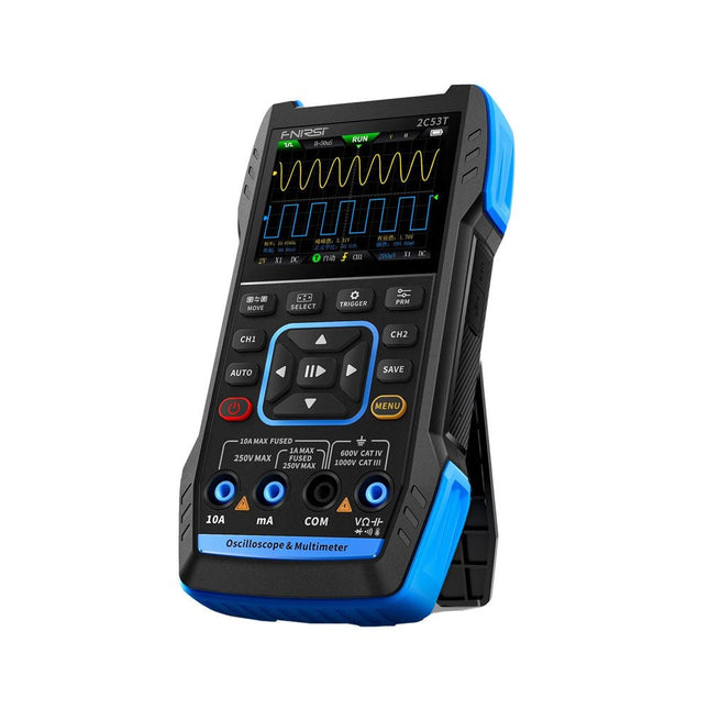
The FNIRSI 2C53T, an enhanced version of its 10 MHz predecessor, is a compact and versatile 3-in-1 device. It combines a dual-channel 50 MHz oscilloscope, a 4.5-digit True RMS multimeter, and a signal generator with 13 waveform types, making it an essential tool for maintenance and research professionals.
Oscilloscope: Features 50 MHz bandwidth, 250 MS/s sampling rate, ±400 V protection, FPGA + ARM + ADC architecture, and waveform saving for analysis.
Multimeter: 4.5-digit True RMS with 19999 counts, supports AC/DC voltage, current, capacitance, resistance, diode, and continuity measurements.
Signal Generator: Outputs 13 signal types up to 50 KHz, with adjustable frequency, amplitude, and duty cycle.
With a 2.8-inch LCD, 3000 mAh battery (6-hour runtime), and a portable design, it delivers powerful functionality in a user-friendly package.
Specifications
Oscilloscope
Channels
2
Analog Bandwidth
50 MHz
Real-time Sampling Rate
250 MS/s
Storage Depth
1 Kpts
Impedance
1 MΩ
Time Base Range
10ns-20s
Vertical Sensitivity
10 mV/div-10 V/div (x1)
Maximum Measured Voltage
±400 V
Trigger Mode
Auto/Normal/Single
Trigger Type
Rising edge, Falling edge
Display Mode
Y-T/Rolling/X-Y
Coupling Method
AC/DC
Persistence
OFF, 500ms, 1s, ∞
Math
8 Basic Operations + FFT
Supported
Waveform Screenshot Save, Export Waveform Image, Cursor Measurement, Infinite Afterglow
Multimeter
DC Voltage
1.9999V/19.999V/199.99V/1000V
±(0.5%+3)
AC Voltage
1.9999V/19.999V/199.99V/750.0V
±(1%+3)
DC Current
19.999mA/199.99mA/1.9999A/9.999A
±(1.2%+3)
AC Current
19.999mA/199.99mA/1.9999A/9.999A
±(1.5%+3)
Resistance
19.999MΩ/1.9999MΩ/199.99KΩ/19.999KΩ
±(0.5%+3)
1.9999KΩ/199.99Ω
±(2.0%+3)
Capacitance
999.9uF/99.99uF/9.999uF/999.9nF/99.99nF/9.999nF
±(2.0%+5)
9.999mF/99.99mF
±(5.0%+20)
Temperature
−55~1300°C (−67~2372°F)
±(2.5%+5)
Continuity Test
Yes
Diode
Yes
Signal Generator
13 Signal Waveforms
Sine wave, rectangular wave, sawtooth wave, half wave, full wave, positive step wave, reverse step wave, exponential rise, exponential fall, DC, multi-audio, Sinker pulse, Lorentz wave
Output Frequency
0-50 KHz
Output Amplitude
0-3 V
Output Duty Cycle
0-100%
General
Display
2.8" HD color screen
Resolution
320 x 240
Charging
USB-C (5 V/1 A)
Battery
3000 mAh Lithium battery
Standby Time
6 hours
Languages
English, Chinese
Dimensions
167 x 89 x 35 mm
Weight
300 g
Differences New vs Old Version
Model
2C53T Upgrade
2C53T Predecessor
Bandwidth
50 MHz
10 MHz
Display Mode
Y-T/Rolling/X-Y
Y-T/Rolling
Math
8 Basic Operations + FFT
N/A
Cursor Function
Yes
N/A
XY Lissau Graph
Yes
N/A
Afterglow Function
Yes
N/A
Multimeter Accuracy
19999 Counts
9999 Counts
Signal Generator
50 KHz
2 MHz
Included
1x FNIRSI 2C53T Oscilloscope (50 MHz)
2x P6100 Oscilloscope probes (10X)
1x Multimeter probe
1x Alligator clip probe
1x USB-C charging cable
1x Storage bag
1x Manual
Downloads
Manual
Firmware V1.2.0
The Siglent SDS1104X-E employs a new generation of SPO (Super Phosphor Oscilloscope) technology that provides excellent signal fidelity and performance. The system noise is also lower than similar products in the industry. It comes with a minimum vertical input range of 500 uV/div, an innovative digital trigger system with high sensitivity and low jitter, and a waveform capture rate of 400,000 frames/sec (sequence mode).
The SDS1104X-E also employs a 256-level intensity grading display function and a color temperature display mode not found in other models in this class. SIGLENT’s latest oscilloscopes offering supports multiple powerful triggering modes including serial bus triggering. Serial decoding is free and includes IIC, SPI, UART, CAN, and LIN. History waveform recording and sequential triggering enable extended waveform recording and analysis. Another powerful addition is the new 1 Mpt FFT math function that gives the SDS1104X-E very high frequency resolution when observing signal spectra.
Features
Intelligent trigger: Edge, Slope, Pulse Width, Window, Runt, Interval, Timeout (Dropout), and Pattern
Free Serial bus triggering and decoding:IIC, SPI, UART, RS232, CAN, and LIN
Video triggers and supports HDTV
Low background noise and 500 μV / div to 10 V / div voltage scales
10 types of one-button shortcuts, supports Auto Setup, Default, Cursors, Measure, Roll, History, Display/Persist, Clear Sweep, Zoom and Print
Segmented acquisition (Sequence) mode, dividing the maximum record length into multiple segments (up to 80,000), according to trigger conditions set by the user, with a very small dead time segment to capture the qualifying event.
History waveform record (History) function, the maximum recorded waveform length is 80,000 frames
Automatic measurement function on 38 parameters, supports Statistics, Gating measurement, Math measurement, History measurement and Ref measurement
1 Mpts FFT
True measurement and math can use all 14 Mpts of memory
Preset key can be customized for user settings or factory “defaults”
Security Erase mode
Highspeed hardware based Pass/ Fail function
Large 7-inch TFT-LCD display with 800 * 480 resolution
Multiple interface types: USB Host, USB Device (USB-TMC), LAN (VXI-11), Pass / Fail, Trigger Out
Supports SCPI remote control commands
Multi-language display and embedded help
Browser control/onboard webpage for software free monitoring (4 channel models only)
Included
1x Siglent SDS1104X-E Oscilloscope
4x 100 MHz probes
1x Guarantee Card
1x Power Cord
1x USB Cable
1x Quick Start Guide
Downloads
Datasheet
Manual
Programming Guide
This book is all about building your own DIY home control system. It presents two innovative ways to assemble such a system: By recycling old PC hardware – possibly extending the life of an old PC, or by using Raspberry Pi. In both cases, the main system outlined in this book will consist of a computer platform, a wireless mains outlet, a controller and a USB webcam – All linked together by Linux.
By using the Raspberry Pi in conjunction with Arduino (used as an advanced I/O system board), it is possible to construct a small, compact, embedded control system offering enhanced capacity for USB integration, webcams, thermal monitoring and communication with the outside world.
The experience required to undertake the projects within this book are minimal exposure to PC hardware and software, the ability to surf the internet, burn a CD-ROM and assemble a small PCB.
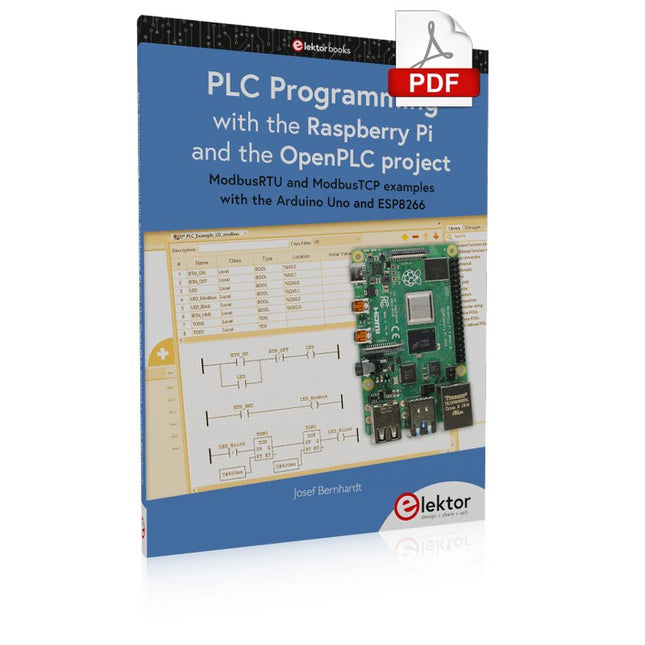
ModbusRTU and ModbusTCP examples with the Arduino Uno and ESP8266
Introduction to PLC programming with OpenPLC, the first fully open source Programmable Logic Controller on the Raspberry Pi, and Modbus examples with Arduino Uno and ESP8266
PLC programming is very common in industry and home automation. This book describes how the Raspberry Pi 4 can be used as a Programmable Logic Controller. Before taking you into the programming, the author starts with the software installation on the Raspberry Pi and the PLC editor on the PC, followed by a description of the hardware.
You'll then find interesting examples in the different programming languages complying with the IEC 61131-3 standard. This manual also explains in detail how to use the PLC editor and how to load and execute the programs on the Raspberry Pi. All IEC languages are explained with examples, starting with LD (Ladder Diagram) over ST (Structured Control Language) to SFC (Special Function Chart). All examples can be downloaded from the author's website.
Networking gets thorough attention too. The Arduino Uno and the ESP8266 are programmed as ModbusRTU or ModbusTCP modules to get access to external peripherals, reading sensors and switching electrical loads. I/O circuits complying with the 24 V industry standard may also be of interest for the reader.
The book ends with an overview of commands for ST and LD. After reading the book, the reader will be able to create his own controllers with the Raspberry Pi.
Hebt u altijd al uw elektronicaproject willen aansturen vanuiteen kleurrijke app op een Android smartphone of tablet? Dat is mogelijk met het in dit boek beschreven Android I/O-board. Met de bijbehorende software-library kunt u in Android Studio eenvoudig zelf een app programmeren die dit mogelijk maakt.
Het Android I/O-board (los verkrijgbaar, wordt niet met boek meegeleverd!) bezit 22 pennen die u vanuit een app kunt aansturen als digitale I/O, ADC, PWM, touch-sensing en counter. Het Android I/O-board kan met de Android smartphone communiceren via Bluetooth, WiFi of USB. Het board is ook als datalogger te gebruiken. Kortom, dit is een veelzijdig board dat in ieder project past.
Dit boek beschrijft stap voor stap hoe u uw project tot een succes kunt maken. Het boek behandelt gestructureerd de volgende onderwerpen:
Een snelle handleiding hoe u uw Android I/O-board up and running krijgt.
Een uitleg van alle mogelijkheden van het Android I/Oboard, met uitgebreide voorbeelden bij de verschillende opties.
Een stap-voor-stap handleiding hoe u een app kunt programmeren in Android Studio.
Een beschrijving van de firmware op het Android I/O-board en hoe u dit zelf met MPLAB-X kunt aanpassen.
Voorbeeld-projecten om inspiratie op te doen hoe u uw eigen project kunt aansturen met het Android I/O-board.
The Siglent SDS1204X-E is a powerful 200 MHz four-channel oscilloscope that is built on the same platform as the very popular SDS1202X-E but with several significant improvements, including two 1 GSa/s ADCs and two 14 Mpt memory modules. Waveform capture rates are up to 100,000 wfms/s in normal mode and 400,000 wfms/s in sequence mode. The SDS1000X-E scopes feature a large 7” 256-level color display with intensity grading and color temperature features.
Specifications
Bandwidth
200 MHz
Sampling Rate (Max.)
1 GSa/s
Channels
2CH+EXT4CH
Memory Depth (Max.)
7 Mpts/CH (not interleave mode); 14 Mpts/CH (interleave mode)
Waveform Capture Rate (Max.)
100,000 wfms/s (normal mode), 400,000 wfms/s (sequence mode)
Trigger Types
Edge, Slope, Pulse width, Window, Runt, Interval, Dropout, Pattern, Video
Serial Trigger (Standard)
I²C, SPI, UART/RS232, CAN, LIN
Decode Type (Standard)
I²C, SPI, UART/RS232, CAN, LIN
16 Digital Channels (four channel series only, option)
Maximum waveform capture rate up to 1 GSa/s, Record length up to 14 Mpts/CH
USB AWG module (four channel series only, option)
One channel, 25 MHz, sample rate of 125 MHz, wave length of 16 kpts
Bode plot ( four channel series only)
Minimum start frequency of 10 Hz, minimum scan bandwith of 500 Hz, maximum scan bandwidth of 120 MHz (dependent on Oscilloscope and AWG bandwidth), 500 maximum scan frequency points
USB WIFI adapter (four channel series only, option)
802.11b/g/b, WPA-PSK, the adapter must be supplied by Siglent to ensure proper functioning
Downloads
Datasheet
Manual
Programming Guide
PIC und AVR verstehen
In diesem Buch werden wir uns ausschließlich mit 8-Bit-Mikrocontrollern beschäftigen, und zwar mit Mikrocontrollern der 8-Bit-PIC- und der 8-Bit-AVR-Mikrocontroller-Linien. Bei der PIC-Familie handelt es sich dabei um PIC10, PIC12, PIC16 und PIC18; bei der AVR-Familie um ATtiny, ATmega und ATxmega. Die vorgestellten 8-Bit-Chips sind für sehr viele Anwendungen vollkommen ausreichend und preislich auch attraktiv.
Durch die Lektüre des Buches erhalten Sie ein fundiertes Wissen über die genannten 8-Bit-Mikrocontroller, über ihre Architektur, ihre Pinbelegungen und über ihre Programmierung.
Weil wir uns in diesem Buch mit den Grundlagen der Architektur der PICs und AVRs vertraut machen möchten, werden wir auch für alle PIC- und AVR-Anwendungen Assembler einsetzen, denn die Assembler-Sprache erlaubt es, die Technik im Detail kennenzulernen. Wenn man wirklich wissen möchte, was sich im Mikrocontroller abspielt, greift man zu Assembler. Damit hat man die beste Gelegenheit, sehr nah an den Kern zu kommen. Und wenn man schon einen Mikrocontroller-Typ kennengelernt und verstanden hat, ist es bei dem nächsten deutlich einfacher, auch wenn er von einem anderen Hersteller kommt. Bei anderen Programmiersprachen bleibt die Technik immer ziemlich tief versteckt.
Die Assembler-Beispiele sind so einfach gestaltet, dass sie jeder mit den im Buch aufgezeigten Programmiertechniken erstellen kann. Weil es sich um einfache Beispiele handelt, werden wir sie alle auf einer universellen Lochrasterplatine realisieren. Manche sind auch auf einem Experimentier-Breadboard umsetzbar.
Dit 216 pagina's tellende e-book staat boordevol Arduino-ideeën, uitleg, tips, diagrammen, programma's, PCB layouts en meer. Genoeg voor dagen vol informatief, inspirerend en stimulerend leesplezier!
Opgemaakt als PDF bevat dit digitale document een inhoudsopgave inclusief links naar elk project, zo dat u gemakkelijk komt waar u wilt zijn. Dit biedt u de mogelijkheid om tussen projecten te wisselen en degene die u het meeste boeien snel en gemakkelijk te vinden.